1
HOME
V700 PRO AUDIO
CLOSE
U796 HOME
EMAIL
PDF Version
User Manual
Stereo Mastering Dynamics Processor U796M2 - 3-Slot / Triple-Wide Version
V700 Mastering Modules
Stereo Mastering Prozessor Home | V700 Mastering Home
The Stereo Mastering Dynamics Processor is available in different versions, which have different control ranges and configurations of particular functions. In
addition, the color of the faceplate and the control knobs can be determined by the customer. Therefore, the appearacne can be different from the the graphics
below. The feature set is identical with all these versions. The modules are available in balanced, grounded (eletronically balanced), and balanced, floating
(transformer balanced) versions. Both versions can be selected for inputs and outputs independently.
The U796 Mastering Dynamics Processor is available in 3 versions, U796M1, U796M2 and the 3-slot version of the U796M2. This page refers to the standard, 2
slot versions U796M2. The 3-slot version is almost identical; however, some additional functions are exisiting. The 2-slot version is here. The U796M is here.
For a general desciption of the module, please change over to the Stereo Mastering Prozessor Homepage
Initial Settings | Quickstart | Options | FAQ's |
PDF Version
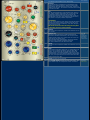
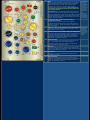
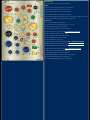
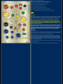
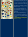
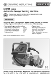
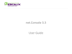
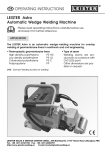
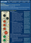
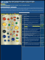
Control Elements
1
Limiter Threshold
sets the threshold of the limiter section between - 6 and
+ 18 dB
2
Limiter Release
modifies the limiter release time from 50 ms to 2.5 sec
3
Limiter Attack
Attack time variation from 20 µsec to 6 ms. With the
minimum attack time the second half wave of a 20 kHz
signal is regulated down to threshold. The longer
settings are only important when using the limiter as
additional compressor section.
4
Limiter Ratio
If an external limiter, like the Mastering Peak Limiter with
Delay U795 is used, the limiter section of the U796 can
be used as additional, independent compressor stage.
The ratio control is only meaningful, if the limiter is used
as compressor.
5
Output Gain
The output gain control only affects the output level but
not the limiter and/or compressor settings. It has a
control range of +/- 10 dB. Output gain is usually
switched on and off together with the limiter.
5a
The GAIN Switch activates the Output Gain Control,
independent of the Limiter. If GAIN is not pressed, it will
be activated if the Limiter is switched on (6)
Notes and
Pecularities
The Limiter
is an
independent
section. The
limiter input
is driven
from the
compressor
output. It is
located
directly pre
the output
drivers of
the dynamics
processor.
With Limiter
Operation
the Ratio
contol has
to be set all
to the right!
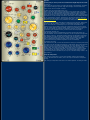
6
The LIM Switch activates the Limiter
7
Compressor Threshold Control
Controls the threshold level of the compressor section in
the range from -32 dBr to + 15 dBr (0 dBr = + 6 dBu ~ +
4 dBV)
8
Crest Switch
The Crest Switch changes the operation mode of the
ac/dc converter from peak (PK) to RMS in 6 steps. Peak
causes a fast and hard regulation with high density,
while RMS results in a soft, loudness related regulation.
The other positions select carefully choosen values
between the two extremes.
The position
of the Crest
switch
determines
the basic
character of
the
compressor.
9
Knee Control
changes the transition from the unregulated range below
threshold to the regulated range above threshold from
hard (0 dB) to soft (20 dB). With the 20 dB setting the
law that is determined by the ratio setting is reached 20
The lower
the ratio
setting is,
the lower is
the incluence
of the soft
dB above threshold. During this level range there is a
successive approximation to the ratio setting.
10
Envelope
A special low filter combined with a modulation of the
release time makes possible to achieve a better bass
compression with low distortion using short, pump free
release time settings. The function is off when the control
is set all to the left.
11
Fill
The Fill-Control adds the uncompressed input signal to
the output (parallel compression) up to a level of 0 dB.
Compressor settings with high gain reduction will
damage the transient structure of the signal. Using Fill
appropriately can cover these damages ('fill the holes')
and result in a higher possible compression.
knee control
ATTENTION:
the fill control adds the input signal, which causes higher
output levels. If this control is not all to the left, input
and output levels will be different, even when the gain
control is set to 0 dB.
Fill should remain all to the left during the first phase
of the setup process to avoid confusion.
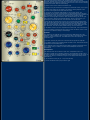
12
12a
Release
determines the compressor release time between 30 ms
and 2.5 sec
Release Law
determines the compressor release characteristics
EXP is the standard characteristic, the first part of the
release phase ist fast but it slows down the closer the
level gets to the steady value
LIN is the alternate characteristics, the entire release
time the level increases constantly and linear
The control fades from one law to the other
13
Attack
determines the compressor attack time between 0.2 and
50 ms
14
Ratio
controls the compressor ratio from 1:1 (Compressor not
active) via oo (limiter operation) up to the 'Over Easy
Range'. In this range the level goes down above the
threshold level. The highest possible output level is the
threshold level. Any level above threshold is attenuated
the more, the higher the level is and the more the ratio
control is set to the right.
15
COMP activates the Compressor
16
The S-C INS switch activates the side chain insert. The
insert affects only the compressor section und makes
The LIN
setting
causes the
impression
of a faster
release time.
A special
Side-Chain
possible to include an external eq that alters the
frequency response under regulation. Expander and
Limiter are not affected.
17
AUTOGAIN OFF
switches the autogain function off
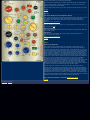
30
Regulation Reverse
the compressor defaults to feedforward regulation. The
REG REV switch selects feedback regulation instead. With
feedback regulation the basic character of the
compression is changed. In addition, the setting of the
gain control (18) affects the threshold setting. In
addition, the scaling of the ratio control is different
(center position ~ 1,8, all to the right ~ 3).
18
Gain Control
controls the output level of the compressor section in a
range of +/- 10 dB. Unless feedback regulation is active,
the control does not affect the compressor settings. .
18a
Autogain Ref
this control determine the reference of the autogain
ciruitry. The autogain reference setting determines two
things at a time
- the output level that is controlled by Autogain to this
value (+ 6 dBu = 0 dBr ~ + 4 dBV +/- setting of the
Autogain Ref Control)
- any input level below this level causes Autogain to
compensate the gain
19
Dynamic Color
adds 2nd harmonics (triode distortion) to the output
signal. The addition is proportional to the compression
rate. (no gain reduction - no distortion, high gain
reduction, high distortion). In addition, distortion
depends on the level (low level - low distortion, high
level - high distortion)
21
Static Color
adds also 2nd harmonics to the output signal; however,
the static control works independent of the gain
reduction and adds a constant percentage of harmonics.
The distortion increases with the level.
22
GR-LIMIT
this control limits the maximum possible gain reduction
down to 3 dB. Using this features lets you compress only
a spefic level range above threshold. As soon as the gain
reduction reaches the limit, the gain reduction remains
constant.
The default setting is all to the right. If this control is
all to the left, the compressor appears to be defective,
since only 3 dB regulation can take place!
Equalizer,
W799 is
available
Custom
control range
is possible
The Color
controls
allow to
simulate the
tonal
behavior of
vintage
compressors.
22
INT
adds long time integration modulation to the regulation
of the compressor. This control can loosen a tight and
hard compression and regain some natural sound
performance; however, it can also result in lower
loudness when not used carefully. This control should
be all to the left during the setup and used at the end
of the setup process.
ATTENTION: due to the long integration time, it takes
several seconds before the effect of a changed setting
becomes audible! If you need to add more INT, use small
steps and wait for the result. If you need to reduce the
setting, set the control all to the left and go to the lower
setting. This will be faster.
The function
is similar to
the 'Auto'
setting of the
release time
in some
compressors.
The major
difference to
INT is that
you
determine
any kind of
automatic by
the position
of the control.
23
Threshold Control of the Expander/Pump-Up
Compressors Section
determines the threshold level of the combined
expander/decompressor/pump-up compressor section
between - 40 and + 15 dBr. This section regulates only
below threshold.
24
Release-Control of the Expander/Pump-Up Compressor The terms
attack and
determines the fade down speed of this section in the
release for
range from .1 sec to 2.5 sec.
25
Attack-Control of the Expander/Pump-Up Compressors
this control determines the fade in time in the range from
.2 ms to 10 ms. With expander mode it controls the
speed the expander opens. With pump-up compressor
operation, it controls the speed of the gain reduction
caused by increasing input levels.
26
Expander Ratio
The ratio control has its inactive position at the center
(1:1) . The range to the right selects pump-up
compressor mode, while the range to the left selects
expander and de-compressor mode
27
GR Limit
this control determines the maximum gain changeof the
section. It is active in all operation modes and covers the
range from 50 dB (max) to 3 dB.
28
EXP Switch
switches on the Expander/DeCompressor/Pump-Up
Compressor section
29
Bypass-Switch
this is the main bypass for the entire module. When
released, the input and output connectors are bridged by
relay. The internal inputs are also switches off; the
inputs do the load the source.
this section
are not quite
clear for the
different
mode.
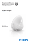
Initial Settings
1. Use the ON Switch (29) to insert the module.
Limiter:
2. Set the Limiter Threshold control (1) all to the right
3. Set the Limiter Release control (2) to 0.3 sec.
4. Set the Limiter Attack control (3) all to the left
5. Set the Limiter Ratio control (4) all to the right
6. Set the Output Gain control (5) to 0 dB, or use a setting, meeting your needs
7. Leave the LIM Switch (6) unpressed for the beginning
Compressor:
8. Set the Crest Switch (8) to position 3
9. Set the Compressor Threshold control (7) to - 18 dB
10. Set the Knee Control (9) all to the left
11. Set the Envelope Control (10) all to the left
12. Set the Fill Control (11) all to the left - IMPORTANT SETTING
13. Set the Release Control (12) to 0.3 sec
14. Set the Release Law Control (12a) to EXP
15. Set the Attack Control (13) to 8 msec
16. Set the Ratio Control (14) to 2
17. Set the Dyn Color Control (19) all to the left - IMPORTANT SETTING
18. Set the GR-Limit Control (20) all to the right - IMPORTANT SETTING
19. Set the Static Color Control (21) all to the left
20. Set the Int Control (22) all to the right - IMPORTANT SETTING
21. Set the Gain Control (18) to 0 dB (Center)
22. Leave the REG-REV switch (30) unpressed
23. Set the AUTOGAIN REF control (18a) to 0 dB (Center)
23. Leave the S-C INS switch (16) unpressed
24. Leave the Autogain Off switch (17) unpressed
25. Switch on the Compressor (15)
Expander/DeCompressor/Pump-Up Compressor:
25. Set the Threshold control (23) to - 15 dB
26. Set the Release control (24) to 0.3 sec
27. Set the Attack control (25) to 6 ms
28. Set the GR-Limit control (27) to 10 dB
29. Set the Ratio control (26) to 1.6 (to the right)
31. Leave the EXP switch unpressed for the beginning (28)
...TOP
Quickstart
The following settings are only one example for an endless number of different
settings. We are leaving out commonly used settings, since we assume that
you are familiar with standard settings in the principle use of compressors.
Before you start trying, please make sure that the controls marked as
IMPORTANT SETTING are set to the recommend initial positions. These
settings control uncommon functions that you won't find in other dynamics
units. Activating these controls in the beginning can cause confusing
behavior of common settings, blur the effects of common controls, or simply
block particular functions.
The following setting results in a natural sounding compression, that causes
high loudness gain, but maintains the transients. It is based on the initial
settings listed above. The text leads you thru the process of adjustment and
will make yourself familiar with the special functions. After going thru this
process, you'll have many own ideas how to use the special features
differently.
Compressor
a) With common input levels, the initial setting should result in approx. 10 dB of
gain reduction. Check the display for the actual gain reduction and adjust the
Threshold control (7) to achieve 10 dB if this not the case.
b) Set the Attack control (13) all to the right. Now the attack time is so long
that all transients will pass thru without causing regulation. Turn the attack
control in little steps to the left. Find the position that maintains the natural
impression and the transients but causes regulation to avoid the 'breakdown'
of the signal after the peaks. You will end in the range between 8 and 16 ms
with most common signals.
c) Try different positions of the Crest switch (8) and find the best suited setting
for the particular mix.
d) Optimize the Release time setting (12). The relase time should be short
enough to avoid audible pump up, but as close as possible to the point where
pumping becomes audible. If the acutal setting causes no pumping, increase
the release time a little (to .6 or .8 sec). If there is still no pumping add gain
reduction by turning the Threshold control (7) one or more clicks to the left. As
soon as you hear pumping reduce the release time (12) and find the point
when pumping dissappears.
e) It is most likely that you will have low frequency distortion after fine tuning
the release control (12). If not, use the Treshold control (7) and increase the
gain reduction until you can hear LF distortion coming up. If you had to change
the Threshold setting (7), check again for pumping and readjust the release
control (12) if pumping is audible. (Just repeat step d in this case)
f) Open the Envelope control (11) until the low frequency distortion disappers.
g) Check the setting and compare the achieved loudness gain by switching the
compressor in and out (15). Make sure that the levels of the compressed and
the uncompressed signal are identical. Most of the gain reduction will be
compensated by the autogain circuitry. If there is still a difference, use the Gain
control (18) to adjust matching levels.
h) Try to fine-tune the setting by repeating the steps above, if you are not
satisfied with the result.
i) You can now try to achieve a higher gain reduction, either by setting the
Threshold control (7) more to the left, or by setting the ratio control (14) more
to the right. A higher gain reduction will always bring up some negative side
effects. At this points the main problem will be the 'demolition' of the signal
structure due to the high gain reduction. Use the Fill control (11) and add the
uncompressed input signal to cover the demolition. Focus on the fine structures
of the signal and find a setting that restores the original without affecting the
compression too much. If the Fill control (11) is wide open, you will loose
loudness gain. Fill is a powerfull tool to achieve higher gain reduction without
typical compressed sound.
j) You will now have a strong, but still good sounding compression with high
loudness gain. However, the short release time that is necessary to avoid
pumping will also result in a behavior that is 'tight and close to the signal'. Its
about time to put some 'air' into it. Open the Int control (22) carefully. Int adds
a long time integration modulation to the regulation. An additional control
circuit generates a control signal from the envelope of the input signal, using
long attack and release times. The Int control (22) adds this signal to modulate
the release time. The release time changes a little as soon as the average
loudness of the input signal is different. This makes the compression less tight;
the mix sounds more natural. If you add too much Int, you will loose loudness,
since the total release time is too slow to drive up the gain after peaks. The
goal of using Int is to maintain loudness, but get rid off the tightness. Try to
find this compromise.
ATTENTION: Int is a long time integration; the reaction on the setting is
very slow! Change the setting in little steps and wait several seconds for
the result before you change again. If you need to turn the control to left, it
is a lot faser to turn the pot all to left for a second and than go to the new
setting. This causes a reset to the circuit.
Options:
At this point you can try some more functions that might improve the result:
k) Knee (9)
Open the knee control and try if a soft knee setting is of advantage. The effect
of a soft knee setting is high with high ratio settings, but lower with lower
ration values, so don't expect a miracle.
l) Static Color (21) and Dynamic Color (19)
These controls add 2nd harmonics distortion to the output signal. The static
color control (21) adds a constant percentage of distortion, while the dynamic
color control (19) adds distortion that is proportional to the gain reduction.
Using this control you will get more distortion with peaks, which comes close to
the behavior of many vintage compressors. With many mixes, adding distortion
is not of advantage. However, depending on the program material adding a
little harmonics can produce a nice and interesting color. (The U794 Harmonics
Distortion Generator offers more possibilities for adding harmonics.)
m) GR-Limit (20)
The GR limit control allows controlling the maximum gain reduction. Setting this
control to 5 dB, for instance, results in a compression that stops at higher
levels. This features is of advantage if you use a multi-compression; for
instance if you use the limiter section for compression of the high level range
with an entirely different setting. Adding 'pressure' and 'density' by raising the
average level below the peaks is also possible; however, the pump-up
compressot (see Expander section), is better suited for this purpose.
n) Regulation Reverse (30)
The compressor section is feedforward controled. The Reverse switch (30)
selects feedback control instead. The behavior of the compressor changes with
this setting; however, Threshold and Ratio settings are affected and the Gain
and Autogain will now also alter the Threshold. The compression is closer to
commonly used vintage compressors. In total with a setting as described
above, feedforward regulation is better suited. However, with more
conventional settings, feedback regulation can be of advantage.
o) Release Law (12a)
The Release Law (12a) controls the characterics during the release phase. With
a setting all to the left (EXP) the behavior is exponential, which means that the
increase in level is controlled by the discharge curve of a capacitor. In the
beginning the level raises fast and gets slower the closer the value gets to the
steady value. The other setting (LIN) causes that the level increases with
constant speed. This setting will result in the impression of a shorter release
time without the the release control (12) is changed. Both settings can be
controlled from EXP to LIN with the pot. Try out, if another setting results in an
improvement.
Pump-Up Compressor
The pump up compressor is one of three possible modes of the expander
section. We start with this mode, since it can improve the above compressor
setting.
The pump up compressor works like an reversed expander. It adds gain when
the level drops below threshold. The regulation takes place only below
threshold. Actually there is no lower limit but a GR-Limit control (27) that avoids
that the pump up compressor raises the noise level too much. We have already
prepared the section with the initial setting.
o) Switch on the section with the EXP switch (28)
p) Check for the gain reduction and readjust the threshold control (23) to get 6
to 9 dB of gain change on the display. The optimum setting depend on the
structure of the signal but lets start with this value.
q) The pump-up compressor adds density in the low level range. The
'breakdown' of the signal is compensated. The big advantage is that the time
constants of the pump-up section can be a lot faster than the time constants of
the compressor, since only the low levels that are not sensitive against
distortion cause high gain reductions. Alter the Ratio setting (26) to the right
and to the left to find the best possible position. Focus on the density; you
should get a result that seems to move the entire mix to the front.
r) Now change the release time (24) and try to find the best possible setting.
The release time with pump-up mode is the time the compressor drives up the
gain when the level drops. This time should be as short as possible, but long
enough to avoid distortion. If no distortion comes up, set the control all to the
left. Otherwise, find the shortest possible setting, free from distortion.
s) The Attack control is of minor importance with this mode, since it determines
the time constant of reducing the gain when the level increases. Check in both
directions, if a different setting is of advantage.
Expander
For mastering, the expander is of minor importance. Meaningful use of the
expander is only possible if there is a high noise floor in the beginning, below
breaks or at the end of the mix. The differences to the use as pump up
compressor are:
t) the Ratio Control (26) has to be on the left side to operate as expander.
u) the Attack control (25) now determines the fade in time. It should be as fast
as possible to avoid audible fade in
v) the Release control (24) determines the fade out speed. If should be set to
0.3 or longer times, if nessary. The noise should dissapear fast but not
switched off.
DeCompressor
The DeCompressor can be used to repair over compressed mixes. The
operation is similar to an expander; however, the threshold level has to be a
lot higher. Usually the original parameters of the compression are not known; a
try and error setting is necessary to figure out an appropriate setting for the
particular mix.
w) set the Ratio control (26) to -1.6 (on the left side)
x) set the Threshold control (23) all to the right
y) set the GR-Limit control (28) to 10 dB for the beginning
z) reduce the Threshold level (23) until you get the impression that you've
found the upper point of the over-compressed signal.
I) readjust the GR-Limit control (28) to determine original threshold level of the
comrpession.
II) Alter the ratio setting (26) and try if another setting offers any advantage
III) Alter the Release (24) and Attack (25) controls to improve the result
IV) Repeat the entire process and try to optimize
Limiter
V) Wait with the Limiter Setting until all other settings are completed.
VI) Switch on the Limiter (6) and adjust the Threshold (1) to a value that
causes 3 dB gain reduction on the LED display next to the limiter section. Make
sure that the attack control is all to the left.
VII) This gain reduction is possible with almost all common mixes and will not
perturb anything. Turn the Treshold control one or two clicks to the left, to
optimize the remaining control and figure out if a higher gain reduction is
possible.
VIII) With more gain reduction you should get either audible pumping or low
frequency distortion or both. Ignore the Low Frequency distortion for a while
and optimize the Release setting (2). If no pumping is aubdilbe, move the
release control to the right until you here pumping. Then turn to the left in
small steps and find the longest possible setting without audible pumping.
IX) Check for low frequency distortion now. If there is any distortion, the only
way out is to reduce the gain reduction. Readjust the Threshold control (1) until
the distortion is not audible anymore.
X) use the Output Gain control (5) to adjust the output level to your needs
The U795 Stereo Mastering Limiter with Delay Line offers aditional functions to
achieve higher gain reduction. Please click on the link for details.
Using the Limiter as additional compressor section.
If an external Limiter is used, the internal Limiter can be used as additional
compressor section. It is best suited to add a tight compression for the high
level range. The possible gain reduction is in the range of 4 to 6 dB. Start with
a release time (2) of 0.3 sec and set the Attack control (3) to 3 msec. A Ratio
setting (4) of 3 to 5 is appropriate.
Adjust the Threshold control (1) until you get about 6 dB gain reduction.
Optimize the release time - like describe in VIII).
Check for low frequency distortion. If there no distortion, you can either set the
Threshold (1) to the left or the Ratio (4) to increase gain reduction. Find the
setting, that offers maximum gain reduction, free from distortion. Check the
release time setting (2) for pumping effects again.
Alter the Attack control and try to find a setting that causes an improvement.
The sound will change in the range from approx. 1 ms to 6 ms, due to the
different regulation of the transients.
Use the Output Gain control (5) to set an output level that meets your needs.
...TOP
Options:
Side Chain Equalizer for the Compressor Section
The U796 has a side chain insert that is activated by the S-C Ins Switch (16). It
only affects the compressor section and leaves limiter and compressor
unchanged. The W799 stereo side chain equalizer is best suited for this
purpose.
Please, check for details here.
Control Ranges
We can adapt the control ranges to your needs. Please let us know what you
are looking for here.
Inputs and Outputs
The module is available with electronically balanced and transformer balanced
inputs and outputs.
Appearance
The colors of the faceplate, the control knobs, and switch caps can be
determined by the customer.
Please, check for details here.
...TOP
FAQ's
What does Autogain do?
The autogain circuit calculates the gain reduction for any settings of the
compressor threshold below 0 dBr. The calculation includes the settings of
threshold, Ratio and Attack. It adds the result of the calculation to the output
gain of the compressor. With short attack times, autogain is very precise (less
than 0.5 dB error over the entire range). When using longer attack times, the
peak output level depends on the transients that pass thru the compressor
without causing regulation. It is not possible to calculate the output level with
longer attack times precisely, since the influence of the structur of the audio
signal is an unknown factor. Measuring the real voltage would be possible but
result not in a static compensation of the gain reduction but an additional
regulation. This is not what the autogain circuit is supposed to do. The
correction with longer attack settings uses an empirically determined law, that
results in an error between 0 and 3 dB over the entire range with common
audio signals. During the setup phasee, the particular controls will only be
changed in little steps, so the precision of the autogain is more than sufficient
to keep the output level constant during that important phase..
Autogain does not consider any external side chain processing, and the
settings of the Fill control and the Envelope control. With real-world settings,
the influence of Fill and Envelope is low and will also not cause any disturbing
differences. An external side chain EQ; however, can alter the gain reduction
considerably. This cannot be be compensated by autogain anyway, since the
autogain does not 'know' the eq setting, nor the spectrum of the audio signal.
The manual gain controls operate independent of the Autogain and are always
available to compensate the any possibly remaining differences.
If you have any questions or comments, please let us know.
...TOP
V700 Index | Sitemap