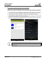
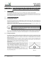
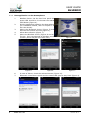
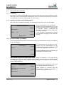
1
USER GUIDE
ELECTROFUSION PROCESS
ON ODS UNITS (TWIN/TWIN-S)
EQUIPPED WITH BLUEBOX
Revision No. 0 - April 2014
Publication: GU-78-09
DATOS DEL FABRICANTE, DISTRIBUIDOR Y SAT:
MANUFACTURER, DISTRIBUTOR AND SERVICE DATA:
ACUSTER GLOBAL, S.L.U.
Juan de la Cierva, 1
Polígono Ind. del Sud-Oest
08960 Sant Just Desvern
SPAIN
Tel. (+34) 93 470 30 70
Fax (+34) 93 473 00 77
e-mail: [email protected]
NOTES !
The device BlueBox is valid for communication to units ODS System
loaded with a software version V. 6.67 or higher.
The modifications carried out against the previous revision of this
publication are indicated with 2 on the right margin.
USER GUIDE
BLUEBOX
CONTENTS:
Page:
CHAPTER 1:
INTRODUCTION..............................................................................
4
1.1 General....................................................................................
4
1.2 Necessary elements...................................................................
4
1.3 TWIN setup............................................................................... 4
1.4 Installing the application and setup Bluetooth................................ 5
CHAPTER 2:
ELECTROFUSION PROCEDURE FOR FITTINGS
TWIN-S UNITS EQUIPPED WITH BLUEBOX.......................................... 6
2.1 Introduction..............................................................................
6
2.2 Fitting preparation jobs............................................................... 6
2.2.1
Scraping pipe surfaces.................................................... 6
2.2.2
Fitting installation........................................................... 6
Edition: April 2014
Revision: No. 0
2.3 Unit preparation.........................................................................
2.3.1
Connection of the fusion box............................................
2.3.2
Previous checks on TWIN box..........................................
2.3.3
Run application on the Smartphone..................................
7
7
7
8
2.4 Electrofusion process..................................................................
2.4.1
Initiation.......................................................................
2.4.2
Operator and job order identification.................................
2.4.3
Fusion jointing traceability...............................................
2.4.4
Auxiliary number............................................................
2.4.5
Preparation of the electrofusion.......................................
2.4.6
Entering the electrofusion parameters..............................
2.4.7
Electrofusion cycle start..................................................
2.4.8
Finalization of the electrofusion cycle................................
9
9
9
9
10
10
10
11
12
GENERAL INDEX -
3
USER GUIDE
BLUEBOX
CHAPTER 1: INTRODUCTION
1.1
GENERAL
The BlueBox device is a hardware that connected to a units ODS System, TWIN and
TWIN-S models, allows, via a Smartphone, sending to a database on the web the
electrofusion records along their photo/s and their GPS location.
1.2
NECESSARY ELEMENTS
For the operation of the described system, the following elements are needed:
1. BlueBox device installed in the TWIN unit.
2. The TWIN unit has the software version v. 6.67 or higher installed.
3. One Smartphone compatible with iOS, Windows Mobile or Android, with BlueBox
application installed. See section 1.4.
4. One ODS scanner.
5. Operator and job order ID.
WARNING !
The Bluebox device makes incompatible the optic pen and the operator and
job order identification becomes compulsory.
1.3
TWIN SETUP
Verify that the scanner is selected as barcode reader. Press INFO and the following
information will be displayed:
INFORMATION
TWIN
Nr. xxxx
SOFT. vx.xx
ENGLISH vx.x
DD-MM-YY
HH:MM
CLIENT
R0/R1 M0/M1
ACCEPT
EC Newton mm
SCANNER
TXXX
Z21
Z41
UFT: 00000 UEF: 00000
LAST REVISION
dd/mm/yy
4
- INTRODUCTION
If OPTIC PEN appears instead of
SCANNER, go to TOOLS / SETUP /
GENERAL / READYING SYSTEM and move
the cursor with the panel arrow ª to select
SCANNER. Press ACCEPT to confirm.
Edition: April 2014
Revision: No. 0
USER GUIDE
BLUEBOX
1.4
INSTALLING THE APPLICATION AND SETUP BLUETOOTH
The site for the download depends on your Smartphone OS: App Store (for iPhone),
Windows Phone Store or Google Play (Android). The examples are done with Android.
1. On the download manager application search bluebox controlpoint. Having found it a
cube of blue colour and text BlueBox ControlPoint (2nd APP in Figure 1) is shown.
2. Download and install the application, accepting the requested permissions.
3. Go to Bluetooth settings, activate it and click on search devices. If necessary, allow
the Smartphone is made visible before searching.
4. Once found, the BlueBox text will be displayed along with the Serial No. of the device.
OK to sync (not required to enter any key). Once synchronized the device appears in
the list of paired devices. See Figure 2.
Figure 1
Figure 2
FURTHER INFORMATION !
If more detailed information is required, refer to the aid provided by the
mobile phone.
Edition: April 2014
Revision: No. 0
INTRODUCTION -
5
USER GUIDE
BLUEBOX
CHAPTER 2: ELECTROFUSION PROCEDURE FOR FITTINGS
TWIN-S UNITS EQUIPPED WITH BLUEBOX
2.1
INTRODUCTION
The procedure described here is only for TWIN units equipped with BlueBox.
The assembly jobs and the PE/PP network electrofusion should always be carried out by
specifically trained personnel and strictly following the manufacturer’s instructions, both
for the fittings as well as the fusion equipment.
2.2
FITTING PREPARATION JOBS
2.2.1 Scraping pipe surfaces:
First clean the surface to be scraped with a clean lint-free dry cloth. The length to be
cleaned will depend on the size of the fitting to be used, adding a minimum additional
margin of 50 mm on each end.
Scrape the area of the pipe or pipes where the fitting to be joined will be installed. The
length of the scraping should be greater than that of the fitting.
IMPORTANT !
The scraping of the pipe should generate swarfs. This ensures the elimination of the pipe’s most exterior oxidation, which would otherwise lead to a
dissatisfactory electrofusion joint.
Next clean the scraped area with a de-greasing towel or with a clean, dry white cloth
(which does not shed lint), dampened with isopropanol or recommended PE solvent.
2.2.2 Fitting installation:
For joints of tapping saddles and branch saddles, place a rounder on each side of the
scraped area if the fusion is performed over a bar pipe. If the joint is performed on a pipe
from a roll, the placement of an aligner-rounder tool is indispensable. Next install the
fitting on the pipe.
If the fitting to be jointed is a coupler, reducer or elbow, remove it from its wrapping, and
without touching its interior, install it on the scraped and cleaned pipe. Now assemble the
aligner and the other specially-prepared pipe or fitting.
Electrofusion joints should only be carried out by
qualified staff.
Protect the area where electrofusions area carried out
from adverse weather conditions, such as rain, snow or
wind. Admissible temperatures range from -10EC to
+40EC. In order to achieve a uniform temperature in
the whole diameter of the pipes, protect the fusion area
against sunrays or bad weather.
The quality of the joint depends substantially on the
care taken in the preliminary preparation tasks (scraping, de-greasing, etc).
Figure 3
6
- MODE OF USE
Edition: April 2014
Revision: No. 0
USER GUIDE
BLUEBOX
2.3
UNIT PREPARATION
2.3.1 Connection of the fusion box:
Connect the fusion control box to a 230 V ± 15% power source (or
to 110V, according to market requirement), of alternating current.
For generator specifications, please refer to CHAPTER 6: TECHNICAL CHARACTERISTICS of the User Manual.
IMPORTANT NOTES !
Connection to a generator: the generator electric connection where
the control box mains is plugged must be normalized and fitted with
differential and ground pin. Refer to the generator’s User Manual.
Connection to the mains: the building electric installation where the
control box mains is plugged must be fitted with earth connection as
well as circuit breaker type D (EN 60898).
Do not unplug the mains pulling on the cable.
The fusion control box can be located either in the vertical or in the horizontal position as
required by the operator.
Set the master switch in the ON position. The display backlight comes on and the
following message is displayed:
MAIN MENU
ELECTRIC BUTT FUSION
ELECTROFUSION
HYDRAULIC BUTT FUSION (TXXX)
TOOLS
ACCEPT
INFO
Familiarize yourself with the push-buttons on the panel. The four push-buttons
© ª ¨ § located below the display are
used in general to move the cursor from
the messages on screen, whereas the
three push-buttons located on the right
side are used to carry out functions
according to what the display indicates.
The push-button <STOP> is used to
interrupt sequences.
2.3.2 Previous checks on TWIN box:
Before starting the electrofusion process selecting the ELECTROFUSION option from the
main menu, check:
To have selected scanner as barcode reader. Press INFO to access to this information.
NOTE !
The option INFO allows us to have access to the general information in
the machine, as well as to the adjustment of the display's contrast.
However, the display contrast can also be adjusted by means or UP and
DOWN key arrows once entered in the ELECTROFUSION mode.
Edition: April 2014
Revision: No. 0
MODE OF USE -
7
USER GUIDE
BLUEBOX
2.3.3 Run application on the Smartphone:
1.
2.
3.
4.
5.
BlueBox Device: On the box front panel the
power LED should be lit whereas the status
LED flashes (Figure 4).
Run the application loaded in the Smartphone
(for installation details, refer to Chapter 1 of
this User Guide).
Select the Bluetooth device (Figure 5) and
activate the location services (Figure 6).
Allow data collection (Figure 7).
Select the BlueBox device (Figures 8 and 9).
The No. 1219 corresponds to BlueBox serial
number (there may be more than one).
Figure 5
6.
7.
8
Figure 6
Figure 4
Figure 7
In case of failure, check the selected device (Figure 10).
Bluetooth connection is made and the status LED goes to stay fixed (Figure 4).
- MODE OF USE
Figure 8
Figure 9
Figure 10
Figure 8
Figure 9
Figure 10
Edition: April 2014
Revision: No. 0
USER GUIDE
BLUEBOX
2.4
ELECTROFUSION PROCESS
2.4.1 Initiation:
Now select the ELECTROFUSION option from the Main Menu and press ACCEPT to start.
The quality of the joints depends substantially upon the care with which the previous work
of preparation (scraping, degreasing, etc.) are made.
2.4.2 Operator and job order identification:
Once the option has been accepted, the following screen will come on the display:
IDENTIFICATION MENU
MANUAL
OPERATOR No.:
ORDER
ACCEPT
No.:
INSERT DATA
CANCEL
These identifications are compulsory.
Proceed to enter the operator’s ID* (via
barcode) and job order No. (via barcode
or manually, either). Completed the
introduction, ACCEPT will be displayed.
Press it to continue.
* The operator’s identification provides
the automatic language set as barcode
entered.
2.4.3 Fusion jointing traceability:
Once having pressed ACCEPT on the operator and job identification screen, the following
screen will appear:
TRACEABILITY
FITTING
MANUAL
ACCEPT
The identification of the fitting is compulsory but the identification of the
components is optional: will be identified
to have the appropriate barcode.
Pressing MANUAL allows manual entry of
component and fitting codes.
CANCEL
After having entered the fitting code, press ACCEPT to validate it. The code will be
recorded on the next line after FITTING. Upon entering the first code, the ACCEPT option
will disappear from the screen, which will then display the field names of the following
codes (COMPONENTS).
TRACEABILITY
FITTING
xxxxxxxxxxxxxxxxxxxxxxxxxx
COMPONENT 1
MANUAL
ACCEPT
Follow the same component code entry
as was performed for the fitting.
Press ACCEPT to continue with the
electrofusion process, or CANCEL to
return to the previous point.
COMPONENT 2
CANCEL
00000000000000000000000000000000000000
Edition: April 2014
Revision: No. 0
MODE OF USE -
9
USER GUIDE
BLUEBOX
2.4.4 Auxiliary number:
Once having pressed ACCEPT on the previous screen (traceability), the following screen
will appear:
AUXILIARY NUMBER
AUXILIARY NUMBER
0000
ACCEPT
Use the keyboard to enter the Auxiliary
number.
These numbers can be changed individually by pressing © or ª to change
values from 0 to 9; press ¨ or § to
move the cursor right or left, respectively.
CANCEL
Press ACCEPT to continue with the fusion jointing process, or CANCEL to return to the
previous point.
2.4.5 Preparation of the electrofusion:
Having executed the operator/job identification operation, and that of traceability and
auxiliary number, the following message will appear:
FITTING DATA
FITTING:
DIAMETER:
INPUT DATA:
REAL RES:
20EC
------ Ohm
MANUAL
Connect the unit electrofusion cable terminals into the fitting's connectors to be
jointed. The contact surfaces of both the
fitting's connectors and cables terminal
must always be clean.
FUSION DATA ?
CANCEL
231 Volt 50 Hz
N.00001
NOTE !
We advise you to always use electrofusion
adaptors, even though the connection to the
fitting may be possible directly. Doing so, the
cable terminals are protected, they do not wear
out, burn, etc.
2.4.6 Entering the electrofusion parameters:
Enter the fitting's electrofusion data via the bar-code system. In the case to be active the
manual option, MANUAL would appear beside the central push-button.
WARNING !
Make sure you always read the bar-code corresponding to the fitting
to be electrofused. Should you not record the fitting's data, this could
cause into errors in the electrofusion process that would have repercussions in the quality and reliability of the joint.
10
- MODE OF USE
Edition: April 2014
Revision: No. 0
USER GUIDE
BLUEBOX
Once the fitting data has been introduced, the display will show the following message:
FITTING DATA
FITTING:
xxxxxxxxxxxx
DIAMETER:
ddd
INPUT DATA: R.RR Ohm / VV.V Volt
REAL RES:
R.RR Ohm
SCRAPED AND CLEANED ?
20EC
231 Volt
50 Hz
YES
The fitting description, size and coded
resistance will be on the screen only in
the case of bar-code system has been
used.
The REAL RES corresponds to the value
of the resistance read on the fitting,
whereas the INPUT DATA corresponds to
the resistance and voltage values provided by the bar-code.
N.00001
If the resistance value between the INPUT DATA and the REAL RES. lie within the preestablished tolerances by the fitting manufacturer, the electrofusion cycle will be able to
proceed. If not, the message "RESISTANCE TOO LOW" or "RESISTANCE TOO HIGH" will
be displayed.
Press YES to continue. The screen will change to:
Press YES or NOT according the fitting
installation used.
FITTING DATA
FITTING:
DIAMETER:
INPUT DATA:
REAL RES:
CLAMP
20EC
xxxxxxxxxxxx
ddd
R.RR Ohm / VV.V Volt
R.RR Ohm
TOOL USED?
231 Volt
50 Hz
N.00001
YES
NO
Pressing either YES or NOT (the use or not of the clamp tool will be recorded in the fusion
records), it goes to the following screen.
2.4.7 Electrofusion cycle start:
By pressing CANCEL you will go back to the initial electrofusion (FUSION DATA?), whereas
by pressing START, the message TAKE PICTURES will be displayed. See NOTE.
NOTICE !
For safety reasons, should you not press the button START during the
starting phase of the electrofusion, after 40 seconds the process will be
cancelled taking you back to the initial screen FUSION DATA ?.
FITTING DATA
FITTING:
xxxxxxxxxxxx
DIAMETER:
ddd
INPUT DATA: R.RR Ohm / VV.V Volt
REAL RES:
R.RR Ohm
TAKE PICTURES:
120s
START
20EC
Edition: April 2014
Revision: No. 0
231 Volt
50 Hz
N.00001
NOTE: not be fixed the LED status of the
BlueBox, the message RUN APP
BLUEBOX will appear. See point 1 of
2.3.3 Run the application.
Once showed the message TAKE PICTURES, it will begin the countdown of
120 seconds to carry out the necessary
photos (minimum 1, maximum 4).
CANCEL
MODE OF USE - 11
USER GUIDE
BLUEBOX
On the Smartphone, the screen in Figure 11 appears. Perform a detailed picture of the
connected fitting (Figure 12). Validate the picture. If deemed necessary, additional
pictures will be taken (maximum of 4). See Figure 13.
NOTE: if the joint is carried out in an interior and there is no GPS tracking, you should
carry a photo (besides the mandatory for the fitting) on the outside to act as joint locator.
Figure 11
Figure 12
Figure 13
Once completed the photo sent (within the assigned time), the electrofusion cycle will
automatically start providing the voltage programmed by the fitting's manufacturer and
the fusion time established according to the correction made depending on the room
temperature. The time and the countdown till you get to zero will come on the display in
seconds.
If there is a malfunction in the electrofusion process, hot molten
PE/PP can be expelled in rare cases. Therefore, keep at a safe
distance from the fusion point during the electrofusion cycle and do
not connect any other electric equipment during the process.
2.4.8 Finalization of the electrofusion cycle:
FITTING DATA
FITTING:
DIAMETER:
INPUT DATA:
REAL RES:
xxxxxxxxxxxx
ddd
R.RR Ohm / VV.V Volt
R.RR Ohm
FUSION TIME: ttt s
MESSAGE ERROR
20EC
231 Volt
50 Hz
If during the fitting's fusion cycle there
is an eventuality such as: disconnection
of a fitting's terminal, increase or decrease of voltage over the allowed limits
by the unit, an electric failure, etc., the
electrofusion process will stop and the
corresponding message will be
displayed.
N.00001
WARNING !
In order to guarantee a good electrofusion, it is recommendable not to
reuse a fitting in which the fusion cycle has been interrupted.
12
- MODE OF USE
Edition: April 2014
Revision: No. 0
USER GUIDE
BLUEBOX
FITTING DATA
FITTING:
DIAMETER:
INPUT DATA:
REAL RES:
xxxxxxxxxxxx
ddd
R.RR Ohm / VV.V Volt
R.RR Ohm
COOLING TIME: tt min.
CORRECT JOINT
20EC
231 Volt
50 Hz
N.00001
GO
If the electrofusion cycle is completed
satisfactorily, the message "CORRECT
JOINT" will be displayed, along with the
perceptive cooling time provided that it
has been given by the fitting's manufacturer. See NOTE.
Whether the joint is correct or not, the
electrofusion record is transferred to the
BlueBox device (Figure 13), which transmits it to the Smartphone to be sent to
the external database (Figure 14).
Press GO to carry out another electrofusion or abandon the menu. In the second case,
close the application in the Smartphone (Figure 15). If turning off the TWIN and not close
the application on the Smartphone, the message Connection Lost appears (Figure 16).
NOTE: The cooling time will be displayed only if the fitting manufacturer has loaded this information on
the bar-code. This indicates the
minimum waiting time that is required before pulling apart the gripping tools used (aligner, clamping
tool, etc). For further information
on the minimum waiting time for
the drilling and pressure test,
please refer to the assembly instructions of the fitting's manufacturer respectively.
Figure 13
Figure 15
Edition: April 2014
Revision: No. 0
Figure 14
Figure 16
MODE OF USE - 13
USER GUIDE
BLUEBOX
NOTES
14
- MODE OF USE
Edition: April 2014
Revision: No. 0