1
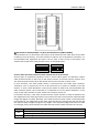
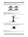
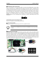
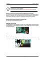
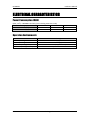
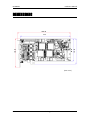
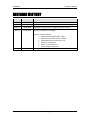
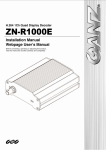
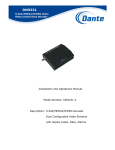
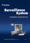
HP4000EX Hardware Manual INFORMATION TO USER CAUTION RISK OF ELECTRIC SHOCK, DO NOT OPEN ! CAUTION: TO REDUCE THE RISK OF ELECTRIC SHOCK, DO NOT REMOVE COVER (OR BACK). NO USER SERVICEABLE PARTS INSIDE. REFER SERVICING TO QUALIFIED SEERIVCE PERSONEL. This symbol is intended to alert the user to the presence of un-insulated “dangerous voltage” within the product’s enclosure that may be of sufficient magnitude to constitute a risk of electric shock to persons. ! This symbol is intended to alert the user to the presence of important operating and maintenance (servicing) instructions in the literature accompanying the appliance. HP4000EX Hardware Manual Table of Contents OVERVIEW ............................................................................................................... 4 PACKAGE CONTENTS ................................................................................................ 5 PRODUCT DESCRIPTION ............................................................................................ 6 Equipment Specifications .......................................................................................................... 6 Summary ............................................................................................................................... 6 System Requirements ........................................................................................................... 7 Functions of Major Connectors ................................................................................................. 8 Major Connectors.................................................................................................................. 8 Details of Major Connectors ................................................................................................. 9 EQUIPMENT FUNCTION .......................................................................................... 14 Video ....................................................................................................................................... 14 Display on External Monitor.................................................................................................... 14 Audio ....................................................................................................................................... 15 Watchdog Function and Connection....................................................................................... 15 Connection with Peripheral Equipment .................................................................................. 17 ELECTRICAL CHARACTERISTICS ................................................................................ 18 Power Consumption (MAX)..................................................................................................... 18 Operation Environments ......................................................................................................... 18 DIMENSIONS .......................................................................................................... 19 TROUBLE SHOOTING .............................................................................................. 20 REVISION HISTORY ................................................................................................. 21 01A.04 UDP Technology Ltd. 3 HP4000EX Hardware Manual OVERVIEW The most outstanding characteristic of the HP4000EX is the capability of H.264 compression of D1@NTSC 16 channel video at 480 frames per second. 01A.04 Video Compression : 720x480 (NTSC) / 720x576 (PAL) at 480/400 frames/sec Compression method : H.264 Baseline Profile and MJPEG Uncompressed video capture : up to 480/400 (NTSC/PAL) frames/sec at 16 channels 16 channels of real-time display (supporting various dividing modes) Compressed audio capture : mono 16 channels, G.711 mulaw compression Uncompressed audio capture : mono 16 channels Video Resolution: Max. 720x576 (PAL) / 720x480 (NTSC) Sensor/Alarm (Max. 16 channel sensor, 16 channel alarm) External monitor display (supporting various dividing modes) Watchdog function supported Multi-card supported Motion detection supported Burnt-in Text supported Privacy Region supported Integrated Software Development Kit (SDK) provided UDP Technology Ltd. 4 HP4000EX Hardware Manual PACKAGE CONTENTS Unpack carefully and handle the equipment with care. The packaging contains: HP4000EX DVI & 16RCA Cable DVI & 16BNC/1RCA Cable i The above contents are subject to change without prior notice. Note 01A.04 UDP Technology Ltd. 5 HP4000EX Hardware Manual PRODUCT DESCRIPTION Equipment Specifications HP4000EX supports two view modes: Multi View mode and Switching View mode. HP4000EX works only one mode of the two view modes regarding the choice of firmware. In the Switching View mode, HP4000EX supports 16 channels video input and 1 switching view output, whereas in the Multi View mode, HP4000EX supports 15 channels video input and 1 multi view output. Summary View Mode Input Channel Display Frame Rate (PAL/NTSC) Raw Data Capture Video Audio Compression Compression Frame Rate (PAL/NTSC) Max. Resolution(PAL/NTSC) Input Channel Raw Audio Capture Bit Per Sample Sampling Frequency Compression Compression Sampling Frequency OSD Burnt-in Text Privacy Region Motion Detection External Video Out Sensor / Alarm RS-485/422 Multi-card Switching View Multi View 16 ch 15 ch 400/480 375/450 Support (YUY2, I420) Support (H.264 Baseline and MJPEG) 400/480 fps@CIF 375/450 fps@CIF 720x576 / 720x480 16 ch 15 ch Support (PCM) 16 bit 8, 16KHz Support (compression mulaw) 8 KHz Support (Overlay, Composite, Compressed data) Support Support Support 1 ch 1 ch (Switching) (Multi-view SD*1, Multi-view HD*2) Support with extension Card Support with extension Card 2 cards *1 Multi-view SD makes limitation of 15 ch encoding. *2 Multi-view HD will be supported in the future and it makes limitation of 14 ch encoding. 01A.04 UDP Technology Ltd. 6 HP4000EX Hardware Manual System Requirements HW Requirement CPU RAM SW Requirement DirectX Tools 01A.04 Intel Core2Duo or higher. 1GB or higher (for single HP4000EX card) DirectX 7.0 or later (8.0 or later recommended) Microsoft Visual C++ 6.0 or later UDP Technology Ltd. 7 HP4000EX Hardware Manual Functions of Major Connectors Major Connectors 10 ○ 9 ○ 11 ○ 2 ○ 8 ○ 1 ○ 7 ○ 3 ○ 4 ○ 5 ○ 18 ○ 12 ○ 13 ○ 14 ○ 15 ○ 6 ○ 16 ○ 17 ○ * Models herein and their appearance are subject to change without any prior notice. 01A.04 UDP Technology Ltd. 8 HP4000EX Hardware Manual Details of Major Connectors 1 DVI Connector for Video Input/output and Audio Input (J1 and J2) ○ There are 2 DVI connectors for video inputs/output and audio inputs. Upper one (J1) is for Video Input Channel 0 ~ 15 (VIN 1st-16th) and Video Output Channel 0 (VOUT_OUT 1st). And lower one (J2) is for audio Input channel 0 ~ 15 (AIN 1st-16th). J2 J1 Video Input 1-16 Audio Input 1-16 2 Video Output Molex 2pin Terminal (J3) for the External Monitor ○ The Molex 2pin terminal for the external monitor has the same circuit function as the RCA connector of DVI to 16BNC/1RCA Cable. It shall be connected to a video input back panel offered separately. GND Video Out J3 3 Audio Output Molex 2pin Terminal (J6) for the External Output ○ Not used. (This will be supported in the future.) Audio Out GND J6 4 Video Input 40pin Box Connector (J7) ○ This is a 40pin box connector for video signal. Functionally, it works the same way as the DVI Connector (J1), but it is operated differently. When using as the video input: The camera shall be connected to the back panel of the video input. The video input back panel and capture card shall be connected by 40pin flat cable. The analog signal of the camera will be put into the capture through the video input back panel and the 40pin flat cable. Be sure to connect the cable correctly using a connector with a protrusion. 01A.04 UDP Technology Ltd. 9 HP4000EX Hardware Manual 5 DIP Switch for Enable/Disable a 75 Ω Termination Resistor (SW1 and SW2) ○ These switches turn on and off the 75Ω resistor at the terminal of the video input. At the time of delivery from the factory, all of the switches in SW1 are set to ON position. Normally, it is recommended that equipment be used in the on state as was set up in the factory. The switches are turned off in some particular cases, as described below. ON ON 1 2 3 4 5 6 7 8 SW1 VIN 1-8 1 2 3 4 5 6 7 8 SW2 VIN 9-16 ※ Cases when the video terminal-resistor switches are to be turned off Several types of equipments generate, send or receive video signals and therefore require video terminal-resistor of 75Ω, such as the camera and the TV monitor and the capture card. The video terminal-resistor 16 pin DIP switch will serve this function in these cases. In most instances, one video output device is connected with one video input. However, sometimes, even a capture card is also to be connected to a camera in addition to the AV monitor. In case a video distributor is used, there will be no need to be concerned about the video terminal-resistor, but occasionally it is impossible to use the video distributor. In this case, set the video terminal- resistor switch of the capture card to off. In the above instance, if the video terminal-resistor switch remains on while it should be off, the magnitude of the video signal will be very weak more than normal and the captured video images will appear very dark. Normally, if the video terminal-resistor switch is turned off when it should be on, the magnitude of the video signal will be very strong more than normal and the captured video images will appear very bright. If the captured image looks either too dark or too bright, firstly check whether the video terminal-resistor switch has been set correctly. Switch ON OFF 01A.04 Description When directly connecting a camera When using an external device without the 75 Ω Termination Resistor When using an external device with the 75 Ω Termination Resistor UDP Technology Ltd. 10 HP4000EX Hardware Manual 6 Audio Input 5pin Molex Connectors (J4, J5, J8, and J9) ○ Four audio channels are connected to one set of 5pin Molex connectors. The HP4000EX is equipped with a connector so that it can be connected with 16 audio channels. 1 2 3 4 5 1 2 3 4 5 J9 J8 GND Audio 1 Audio 2 Audio 4 Audio 3 GND Audio 5 Audio 6 1 2 3 4 5 Audio 8 Audio 7 1 2 3 4 5 J4 GND Audio 9 Audio 10 Audio 12 Audio 11 J5 GND Audio 13 Audio 14 Audio 16 Audio 15 7 Cooler Fan for Video Processor ○ This is used for cooling Video Processors and located on the Video Processors. 8 Molex 3pin Terminal for supplying Power (J12) ○ This is used for supplying power to the Cooler Fan and is connected to the 3-Pin Cooler Fan Connector. Red Yellow Black 3-Pin Cooler Fan Connector J12 FAN_STEP VCC_12_ 0 GND 9 4 pin Connector for I2C (J15) ○ This connector is used to connect with the I2C extension card (example: EIO card), The 4 pin cable is used for the connection. The EIO card is not supplied as a basic accessory. Details will be explained in the extension card hardware manual separately supplied. 1234 J15 +5V SDA GND SCL 10 Watchdog Buzzer (BZ1) ○ If a system halts unexpectedly, the buzzer will sound for notifying users of the system malfunctions and then the system will reboot. 01A.04 UDP Technology Ltd. 11 HP4000EX Hardware Manual 11 Watchdog pin header (J19 and J20) ○ This is a 2pin header for connecting the cables. To connect the watchdog cable, 2 sets of 2pin cable are required. One is supplied with the capture card and the other is replaced by the existing reset cable enclosed in the case of the SYSTEM. Firstly, the cable in the reset terminal of the SYSTEM case shall be connected to the J19 terminal of the watchdog. The other cable is to be connected to the J20 terminal of the watchdog and the reset terminal of the mother board. The watchdog pin header has no polarity or direction. Therefore, the cable may be plugged in the reverse direction or the connection of J19 and J20 may be interchanged. Detailed functions of the watchdog will be explained in Chapter "Watchdog functions and connection." J19 J20 12 Mini 20pin Connector for Debug port (J11) ○ This port is used when manufacturing in the factory. 13 2 pin Dip Switch (SW3) ○ This port is used when manufacturing in the factory. (Default: On/On) i Note It should be set as ON/ON states; otherwise the HP4000EX cannot be operated normally. 14 SATA Power Connector (J15) ○ HP4000EX requires an additional SATA Power connection, which means you should connect SATA Power cable from a power supply to HP4000EX as following picture. Because PCI Express slot does not supply 5V from a slot. Also HP4000EX requires an additional 3.3V power from the SATA power cable. However, you cannot use a 4-pin Molex to SATA power gender. Because the 4-pin Molex connectors do not provide 3.3 V power, these adapters provide only 5 V and 12 V power and leave the 3.3 V lines unconnected. So you should connect 5-wire SATA power cable to this connector for supplying 3.3V, 5V, and 12V power to HP4000EX. Do not use! 01A.04 Do not use! UDP Technology Ltd. 5-wire SATA Power Cable Wire Color Function 1 Orange 3.3V 2 Black Ground 3 Red 5V 4 Black Ground 5 Yellow 12V 12 HP4000EX i Note Hardware Manual If BIOS does not recognize HP4000EX, Please check whether the additional 5-wire SATA power cable is connected. 15 20pin Box Connector for connecting the Sensor/Alarm Extension Card (J17) ○ This connector is used to connect with the sensor/alarm extension card. The 20pin flat cable is used for the connection. The sensor/alarm extension card is not supplied as a basic accessory. Details will be explained in the extension card hardware manual separately supplied. 16 Video Output 16pin Box Connector for HDMI port (J16) ○ Not used. (This will be supported in the future.) 17 uP (Micro-Processor) LED ○ This LED displays the micro-processor is operating. The uP LED will blink two times when the micro-processor is recognized correctly. And the uP LED will blink when using an extension card via I2C connector. 18 VP (Video Processor) LED ○ You can verify the state of the video processors. If some LED is not turned on, it means that one of the video processors does not work. st 1 VP nd 2 VP rd 3 VP th 4 VP 01A.04 UDP Technology Ltd. 13 HP4000EX Hardware Manual EQUIPMENT FUNCTION Video Video Input Channel: 16ch (Switching View Mode), 15ch (Multi View Mode) Input: Color Camera (NTSC/PAL), black & white camera Connection: BNC Port or 40pin flat cable (for connection with video input back panel) Recommended signal range: 0.5V ~ 2V (p-p) Video Connections Connect the camera to the Video input connectors on the back panel using 75 ohm video coaxial cables with a BNC connector. DVI & 16BNC/1RCA Cable This cable is used for HP4000EX. It has 16BNC Connectors for Video input and 1RCA Connector for external monitor. RCA Connector * The appearance or color of a cable is subject to change without any prior notice. Display on External Monitor Channel: 1 ch (supporting various dividing modes) Connection: RCA Port or Video Output Molex 2pin Terminal Video output RCA Connector for external monitor This RCA output jack is for displaying on the external monitor, and is connected to the video input terminal of the TV monitor. Video Out GND ⑤ 01A.04 UDP Technology Ltd. 14 HP4000EX Hardware Manual Audio Audio input Channel: 16ch (Switching View Mode) 15ch (Multi View Mode) Input: Microphone, line in (mono) Connection: 5pin Molex connector Recommended signal range: Max 2.16V (p-p) DVI & 16RCA Cable This cable is used for HP4000EX. It has 16RCA Connectors for Audio input. * The appearance or color of a cable is subject to change without any prior notice. Watchdog Function and Connection The watchdog is composed of the SYSTEM resetting section and buzzer. The process of resetting the system by the watchdog is similar to pressing the reset button of the system by the system user. So as not to surprise the user by the sudden resetting of the system by the watchdog, it can be set to sound a buzzer to warn of impending resetting. The watchdog initially remains at function stop state and was designed to reset without sounding a buzzer. To sound the buzzer prior to watchdog resetting, it is required to make the software control the watchdog and set the time of sounding the buzzer. The watchdog function in the software stops when the system is newly booted or reset by the watchdog so it is necessary to set the watchdog function every time. The watchdog cannot recognize that the system was reset by the user by pressing the reset button. In case the system is reset by way of the reset button on the system while the watchdog is in operation, be wary because the system may be reset again by the watchdog before the system booting is completed. Two sets of 2pin cable are required to connect the watchdog cable. One is supplied with the capture card and the other is replaced by the existing reset cable enclosed in the case of the system. Firstly, the cable in the reset terminal of the system case shall be connected to the J19 terminal of the watchdog. The watchdog pin header has no polarity or direction. As such, the cable may be plugged in the reverse direction or the connection of J19 and J20 may be interchanged. Below diagram depicts the example of watchdog cable connection. 01A.04 UDP Technology Ltd. 15 HP4000EX Hardware Manual PC Reset Switch RST PWSW HDD LED HP4000EX Front Panel Jumper of the Motherboard It shows an example of the reset pin header of the motherboard. The actual location or figure is varied depending on the motherboard. Before connecting, please refer to the motherboard user’s manual and make a connection after confirming the correct position. 01A.04 UDP Technology Ltd. 16 HP4000EX Hardware Manual Connection with Peripheral Equipment Connect to an external monitor Connect to input back Panel when using as the video input HP4000EX Connect to DIO connectors of ConExt1616, ConExt1200, ConExt0012, ConExt1604 and ConExt0404 Connect to the output terminal of audio input device (microphone, line and etc) by using AIN 1~16 RCA Cable Terminal of video input device (camera, VCR and etc) by using VIN 1~16 BNC cable 01A.04 UDP Technology Ltd. 17 HP4000EX Hardware Manual ELECTRICAL CHARACTERISTICS Power Consumption (MAX) (Max, ± 5%) – HP4000EX card only (not including extension cards) Voltage [V] +3.3 V +5 V Current [mA] 190 140 Power [W] 0.597 0.670 +12 V 2200 25.54 Operation Environments Parameter Video Input range Audio Input range Ambient Operating Temperature Ambient Operating Humidity 01A.04 Limited Range 0.5V ~ 2V (p-p), 75Ω Max 2.16V (p-p) 0 ºC ~ 50 ºC (32 ºF ~ 122 ºF) Up to 90% RH UDP Technology Ltd. 18 HP4000EX Hardware Manual DIMENSIONS 238.36 111.18 126.36 98.43 225 (Unit: mm) 01A.04 UDP Technology Ltd. 19 HP4000EX Hardware Manual TROUBLE SHOOTING 01A.04 UDP Technology Ltd. 20 HP4000EX Hardware Manual REVISION HISTORY MAN# DATE(M/D/Y) Comments 01A.00 09/21/2009 Created. 01A.01 09/28/2009 Corrected the Color of the 3-Pin Cooler Fan Connector. 01A.02 10/28/2009 Operation Temperature is changed from 60℃ to 50℃. 01A.03 11/09/2009 Power consumption is changed SDK V1.2 Official Release Added Audio Sampling Rate : 16Khz Added Compression Format : MJPEG Added 40pin box connector pin out Multi-card supported Burnt-in Text supported Privacy Region supported 01A.04 01A.04 12/04/2009 Removed supported OS UDP Technology Ltd. 21