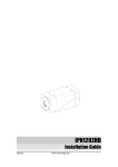
1
ZN-R1000E
Installation Manual
Webpage User's Manual
Table of Contents
1. PACKAGE CONTENTS .............................................................................................. 5 2. INTRODUCTION ...................................................................................................... 6 2.1. Main Features .................................................................................................................... 6 2.2. Hardware Overview ........................................................................................................... 7 2.2.1. Front Panel .................................................................................................................. 7 2.2.2. Rear Panel ................................................................................................................... 8 3. Installation ............................................................................................................. 9 3.1. Video Output Configuration Switch ................................................................................... 9 3.2. Cabling.............................................................................................................................. 10 3.3. Wall‐Mounting ................................................................................................................. 14 4. Basic Setup ........................................................................................................... 15 4.1. Network Setup ................................................................................................................. 15 4.2. System Configuration on Web Page................................................................................. 16 4.3. Video Display.................................................................................................................... 17 4.4. Reset................................................................................................................................. 18 4.5. Factory Default................................................................................................................. 18 5. How to Use OSD Menu ......................................................................................... 19 5.1. Menu Configuration ......................................................................................................... 19 5.2. Display Mode.................................................................................................................... 21 5.2.1. Quad View ................................................................................................................. 21 5.2.2. Single View ................................................................................................................ 21 5.2.3. PIP View..................................................................................................................... 21 5.3. Audio Mode...................................................................................................................... 23 5.4. Quick Menu ...................................................................................................................... 23 5.4.1. Changing connection mode ...................................................................................... 23 5.4.2. Checking device and channel information ................................................................ 24 5.4.3. Rebooting device....................................................................................................... 24 6. How to Use Web Page .......................................................................................... 25 6.1. Recommended PC specification....................................................................................... 25 6.2. Basic Configuration .......................................................................................................... 26 6.2.1. User management..................................................................................................... 26 6.2.3. Setting date and time of device ................................................................................ 30 6.3. Encoder Setting ................................................................................................................ 32 Rev1.0
2
ZN-R1000E
Installation Manual
Webpage User's Manual
6.4. Decoder Setting................................................................................................................ 34 6.4.1.View............................................................................................................................ 34 6.4.2. OSD............................................................................................................................ 35 6.4.3. Audio ......................................................................................................................... 36 6.5. Event Configuration.......................................................................................................... 36 6.5.1. How to configure each event server ......................................................................... 37 6.5.2. Assigning event rule to event publishers .................................................................. 39 6.6. SYSTEM OPTION ............................................................................................................... 41 6.6.1. TCP/IP (DHCP, Static IP, DNS setup) setup ................................................................ 41 6.6.2. NTP server setup ....................................................................................................... 42 6.6.3. UPnP setup ................................................................................................................ 43 6.6.4. mDNS (Multicast DNS) setup .................................................................................... 44 6.6.5. SMTP setup................................................................................................................ 45 6.6.6. LED Setup .................................................................................................................. 47 6.6.7. DDNS (Dynamic DNS) ................................................................................................ 48 6.6.8. SNMP......................................................................................................................... 49 6.7. IO CONFIGURATION ......................................................................................................... 50 6.7.1. DI/DO control ............................................................................................................ 50 6.7.2. UART setting for serial device ................................................................................... 52 6.8. MAINTENANCE ................................................................................................................. 54 6.8.1. Firmware update port setup ..................................................................................... 54 6.8.2. Getting system Log.................................................................................................... 54 6.9. ABOUT .............................................................................................................................. 55 6.9.1. Version ...................................................................................................................... 55 6.9.2. Licenses ..................................................................................................................... 55 APPENDIX (A): SPECIFICATIONS ................................................................................ 56 Summary ................................................................................................................................. 56 Electrical Characteristics ......................................................................................................... 56 Environment Condition ........................................................................................................... 57 Mechanical Condition ............................................................................................................. 57 APPENDIX (B): POWER OVER ETHERNET................................................................... 58 PoE compatibility .................................................................................................................... 58 Power classification................................................................................................................. 58 APPENDIX (C): DIMENSIONS ..................................................................................... 59 REVISION HISTORY ................................................................................................... 60 Rev1.0
3
ZN-R1000E
Installation Manual
Webpage User's Manual
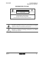
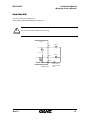
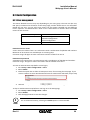
INFORMATION TO USER CAUTION RISK OF ELECTRIC SHOCK, DO NOT OPEN !
CAUTION: TO REDUCE THE RISK OF ELECTRIC SHOCK, DO NOT REMOVE COVER (OR BACK). NO USER SERVICEABLE PARTS INSIDE. REFER SERVICING TO QUALIFIED SEERIVCE PERSONEL. !
Rev1.0
This symbol is intended to alert the user to the presence of un‐insulated “dangerous voltage” within the product’s enclosure that may be of sufficient magnitude to constitute a risk of electric shock to persons. This symbol is intended to alert the user to the presence of important operating and maintenance (servicing) instructions in the literature accompanying the appliance. 4
ZN-R1000E
Installation Manual
Webpage User's Manual
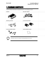
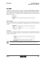
1. PACKAGE CONTENTS
Unpack carefully and handle the equipment with care. The packaging contains: Decoder DC power adaptor Mounting brackets 9‐pin terminal blocks Screws and anchor blocks Quick installation guide i
The above contents are subject to change without prior notice. Note Rev1.0
5
ZN-R1000E
Installation Manual
Webpage User's Manual
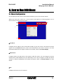
2. INTRODUCTION
2.1. Main Features
The Network Video Decoder enables decoding of H.264, MPEG4, and MJPEG streams from IP devices and displaying decoded images on a monitor. For its main features, refer to the following summary. •
•
•
•
•
1‐channel H.264 30fps@D1 decompression Up to 4‐channel H.264 30fps@CIF decompression Decompress H.264, MPEG‐4, and MJPEG streams Audio compression and decompression: G.711 System configuration on a webpage Rev1.0
6
ZN-R1000E
Installation Manual
Webpage User's Manual
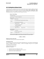
2.2. Hardware Overview
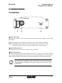
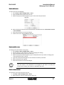
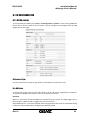
2.2.1. Front Panel
1CH Decoder
Status
NTSC
Data
1
○
PAL
OFF
Vout
2 ○
3
○
1 System status LEDs ○
The LEDs are located on the left side of the front panel and they indicate certain system information. Status This LED lights up as orange and turns green when the decoder is powered on. Data This LED lights up when the host system is turned on with a connection is made. (The color of LEDs is subject to change according to the firmware version) 2 Loop out BNC connector ○
As a loop out connector, connect to a device such as a monitor. 3 Output setting switch ○
This button enables to turn the video output on or off on a monitor. If you set this switch to Off, no image will be displayed on the monitor. To turn the video output on, set this button to NTSC or PAL according to the IP device’s video format before you connect the power cable. i
Note Rev1.0
The video output configuration must be set before you connect the power cable. Changing the setting after the device is turned on will not affect on the configuration. 7
ZN-R1000E
Installation Manual
Webpage User's Manual
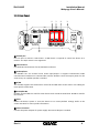
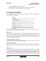
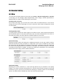
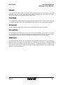
2.3.2. Rear Panel
6
○
4 ○
Ain
1
USB
DI
1 2
Ethernet
5 ○
7
○
8
○
9
○
RS-232
Rx Tx
DC12V
1
Reset
1 2 C
Aout
DO
RS-485
10 ○
④ USB 2.0 port Use this port to connect a USB mouse. A USB mouse is required to control the device on a monitor. The PS/2 mouse is not supported. ⑤ LAN connector Use the RJ45 LAN connector for 10/100 Base‐T Ethernet. ⑥ Audio IN/OUT The decoder has one channel mono audio input/output. It supports bi‐directional audio communication between an H.264 encoder and the decoder. Since the output power for the audio is low, an amplifier speaker is needed. ⑦ DI/DO The encoder supports two channels for each of DI and DO. Refer to the section 3.2. Cabling for more specific information. ⑧ RS‐232/RS‐485 RS‐232C Terminal Block is used for some devices such as POS terminal block. RS‐485 is used for PTZ controls. ⑨ Reset Reboot the device system or reset the device to its Factory default settings. Refer to the section 4.4 Reset for more specific information. ⑩ Power connector Connect the power adaptor for power supply. DC 12V 1A adaptor is needed. Rev1.0
8
ZN-R1000E
Installation Manual
Webpage User's Manual
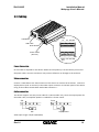
3. Installation
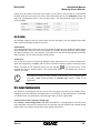
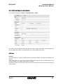
3.1. Video Output Configuration Switch
The video output configuration switch enables to turn the video output on or off on a monitor. If you set this switch to Off, no image will be displayed on the monitor but a black screen. To turn the video output on, set this switch to NTSC or PAL according to the IP device’s video format before you connect the power cable. If you want to change its output configuration after the power cable is connected, put the switch to the desired position and reboot the system. To learn how to reset your device, refer to 4.4. Reset. Video Out Output Configuration Switch NTSC
PAL
OFF
i
Note The video output configuration must be set before you turn on the device. Changing the setting after the device is turned on will not affect on the configuration. Rev1.0
9
ZN-R1000E
Installation Manual
Webpage User's Manual
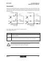
3.2. Cabling
Audio In DI RS‐232 USB Mouse
LAN Cable Reset Button Power Cable (DC 12V) Audio DO RS‐485 Out Power Connection
DC 12V cable is required for thie device. Make sure the polarity is correct before you connect the power cable. Incorrect connection may cause malfunction or damage to the IP device. Video connection
Connect a LAN cable to the LAN connector of the device to retrieve the IP devices. Connect a display device (such as monitor) to the Video output connector on the back panel of the device using 75 ohm video coaxial cables with a BNC connector. c Audio connection
The device supports two way mono audio for H.264 encoder only. Since the output power for the audio is low, an amplifier speaker is needed for a clearer sound. Ain
Aout
Mic Amp Speaker
Audio input range: 0.01/3.3 (Min/Max) Rev1.0
10
ZN-R1000E
Installation Manual
Webpage User's Manual
Sensor Input (D/I)
There are two sensor interface types – Voltage Type and Relay Type. The interface type can be controlled by the software. Before connecting sensors, check driving voltage and output signal type of the sensor. Be aware that the connection is different according to sensor type before connecting cables. Internal +5V Internal Output of Sensor 1 DI 1 +
‐
Output of Sensor 1
DI 1 ‐
+
+5V DI 2 Output of Sensor 2
‐
+
DI 2 COM Output of Sensor 2 +
‐
COM ‐
+ +5VDC~+24VDC
Relay Type Voltage Type Input voltage range: 0 VDC minimum to 24 VDC maximum Input voltage threshold: 1 V Signal Description COM Connect (‐) cable of electronic power source for sensors to this port as shown in the circuit above. D1~D2 Connect output of sensors for each port as shown in the circuit above. !
Caution Do not exceed the maximum input voltage or relay rate. Do not use voltage and relay type sensor together. Rev1.0
11
ZN-R1000E
Installation Manual
Webpage User's Manual
Alarm Output (D/O)
Only the relay type is supported. Relay Rating: Max 24VAC 500mA or 12VDC 1A !
Do not exceed the maximum relay rating. Caution Internal Device
DO 1
Device
DO 2
COM
Relay Type Rev1.0
X
Max 12VDC 1A
or 24VAC 500mA Power 12
ZN-R1000E
Installation Manual
Webpage User's Manual
RS-232C Connection
RS‐232C Terminal Block is used for some devices such as POS terminal block. <RS- 232C Applic ation>
RX
TX
G ND
TX
RX
G ND
RX TX G ND
RS-485 Connection
The RS‐485 serial port consists of TRX+(RX+) and TRX‐(RX‐) as following. 485 Device Rev1.0
13
ZN-R1000E
Installation Manual
Webpage User's Manual
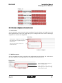
3.3. Wall-Mounting
To wall mount your device, follow the instructions below. 1) Drill two holes on the wall and insert anchor blocks into the holes. 2) Put the mounting brackets to the mounting hole on each side of the device. 3) Fasten the device with screws. 4) Make sure the device is firmly installed. Rev1.0
14
ZN-R1000E
Installation Manual
Webpage User's Manual
4. Basic Setup
4.1. Network Setup
The default IP address of your IP device is 192.168.XXX.XXX. You can find the available IP address from the MAC address of your device. Please make sure the device and your PC are on the same network segment before the installation. If the network segment of your PC is different from the device, change your PC’s IP setting as below. IP address : 192.168.xxx.xxx Subnet mask: 255.255.0.0 Rev1.0
15
ZN-R1000E
Installation Manual
Webpage User's Manual
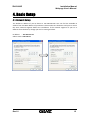
4.2. System Configuration on Web Page
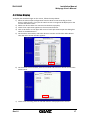
You can set up the system configuration on a web page of your device. Follow the directions below to use its web page for the system configuration. 1) Convert a MAC address to an IP address or check the IP address on the IPAminTool. (The MAC address is attached on the side or bottom of the device.) MAC address = 00‐1C‐B8‐01‐14‐B1 → IP address = 192.168.20.177
the Hexadecimal number to Decimal number.
2) Open a web browser and enter the IP address of the device. You also can right click on the device on the IPAdminTool and select Web view. 3) Enter the default user name (root) and password (pass) and click the OK button. 4) When the Setup page appears, click System Options on the left and then select TCP/IP from the drop‐down menu. 5) Input the data for the IP address configuration, and click the Apply button on the bottom of the page. To change the IP address, please make sure to check and have the correct Subnet mask and Gateway ready. To use DHCP, select Obtain an IP address via DHCP. 6) Set up the necessary system configuration on the web page. Refer to Chapter 6. How to Use Web Page for details. IPAdminTool automatically searches all activated network encoders and IP cameras and shows product name, IP address, MAC address, etc. To search your device and use its web page more easily, use IPAdminTool that is provided with SDK at the following SDK path. {SDK root}\BIN\TOOLS\AdminTool\ Rev1.0
16
ZN-R1000E
Installation Manual
Webpage User's Manual
4.3. Video Display
To display the decoded images on the screen, follow the steps below. 1) Move the video output configuration switch to NTSC or PAL according to the IP device’s video format. If you put the switch to OFF no image will be displayed on the monitor but black screen. 2) Make sure all the cables are connected to the device properly. 3) Check if the 4 split‐view appears on the connected monitor. 4) Click on No device on the upper left corner of each split view to open the dialog box which list available devices. 5) On the Device list window, select the device to connect and click the Select button. Then the Select stream window appears. Camera 1 Camera 2 Camera 3 Camera 4 Camera 6 Camera 7 Camera 8 Encoder 1 Encoder 2 Encoder 3 Encoder 4 Encoder 5 Encoder 6 Encoder 7 6) On the Select stream window, Select the channel and stream to decode and click the Select button. Camera 1
7) Check if the streaming video of selected IP device is displayed on the screen. Rev1.0
17
ZN-R1000E
i
Note Installation Manual
Webpage User's Manual
The video output configuration must be set before you turn on the device. Changing the setting after the device is turned on will not affect on the configuration. Video transport performance
The videos displayed on the 4 channels in a view may not have satisfactory quality due to limitation of DSP resource. To configure the channels with a relevant level, refer to the following test table for video transport performance. Codec H.264 MPEG‐4 MJPEG H.264 MPEG‐4 MJPEG Resolution GoP (Quality)
D1 CIF 29 29 50 29 29 50 Bit rate
FPS (1ch)
FPS (4ch) 1M 1M 4M 1M 3.5M 4M 15 26 18 30 30 30 60 104 72 120 120 120 If you want to keep one of the four channels to have the best image quality without interference of other three channels, you can use the Priority Channel Configuration option on the web page of your device. Refer to Channel performance on 6.3.1. View for more details. 4.4. Reset
Perform the following procedures to reset your device: 1. While the device is in use, press and hold the Reset button. 2. Release the Reset button after 3 seconds. 3. Wait for the system to reboot. 4.5. Factory Default
If you reset your device to the factory default setting, all parameters including the IP address will be initialized. For the Factory Default reset: 1. Disconnect the power supply from the device. 2. Connect the power to the device with the Reset button pressed and held. 3. Release the Reset button after 5 seconds. 4. Wait for the system to reboot. Rev1.0
18
ZN-R1000E
Installation Manual
Webpage User's Manual
5. How to Use OSD Menu
5.1. Menu Configuration
On the display monitor that is connected to the device, you can use several menus. When you move your mouse on a view channel, OSD appears as following figure. For its feature refer to the descriptions below. IP address It displays the IP address of the connected encoder. If you click on this, the Device List menu appears. On the Device List menu, select the desired device you want to connect. For more information about how to display a video of an encoder, refer to 4.3. Video Display. Quick menu It appears when you right‐click on the monitor. With this menu, you can change the current display with a preset display that is pre‐defined by a user. Thus, it supports to check the device version or channel configuration and reboot the device. Refer to 5.5.Quick Menu for more details. FPS It displays the frame rate of a channel. Rev1.0
19
ZN-R1000E
Installation Manual
Webpage User's Manual
Shortcut Icons With the shortcut icons, you can enable audio or change the display mode. Refer to 5.2. Display Mode and 5.3. Audio Mode for more details. Rev1.0
20
ZN-R1000E
Installation Manual
Webpage User's Manual
5.2. Display Mode
The device supports quad view, single view, and PIP view. The default view mode is quad view. 5.2.1. Quad View
In the Quad View mode, the evenly split four‐windows appear on the screen. On the quad view mode, you can change the view to the single view mode only. To change the display mode on this default view mode, move your mouse point to the right top of the desired channel. Then image icons appear as shown below. If you click the Display Mode icon, the selected split view is displayed in a single view. 2 1
○
○
Enable audio 5.2.2. Single View
In the Single View mode, only one video is displayed on the screen. You can change the view either to a different channel or to different splits. To change the display mode to different views, move your mouse point to the right top of the view. Then image icons appear as shown below. Select the desired view mod. 2 1 ○
○
3 ○
4
○
Enable audio Enable quad view Switch the channel Enable PIP mode 5.2.3. PIP View
In the PIP View mode, you can see one other video with a small split in a full single view. You can switch the full image with the small inset image or change the view with different splits. To switch the image that is displayed in the sub‐window with the full screen image, click below. To switch the channel in the sub‐window to a different channel, click the desired channel from . If you want to change the view mode from PIP to a different one, move your mouse point to Rev1.0
21
ZN-R1000E
Installation Manual
Webpage User's Manual
the right top of the full image view, and then select the desired view by referring to the icons described on 5.2.2. Single View. 1 2
○
○
Switch full‐window with sub‐window Rev1.0
22
ZN-R1000E
Installation Manual
Webpage User's Manual
5.3. Audio Mode
If you click the Enable Audio button from the shortcut icons, you can hear the output sound. When the audio output is enabled, the icon will be changed as the following figure.
Audio disabled
Audio enabled
To hear the output sound, make sure that the audio input/output cable is properly connected with a microphone and speaker. To learn how to connect audio cables, refer to 3.2. Cabling. 5.4. Quick Menu
If you right‐click on a view, the Quick Menu appears as below. This menu helps you to change connection mode, reboot the device, or check its version. Changes the view with the selected monde Check boxes for selecting a connection mode Displays the channel configuarions Saves the channel configurations (Available only in Preset Mode) Displays the version of device Closes the quick menu Reboots device
5.4.1. Changing connection mode
The decoder supports two different connection modes: Instant Mode and Preset Mode. The instant mode enables you to immediately change the video channels and display them on the screen. The preset mode is useful to save the channels you want to view and display them just by clicking the configured preset view. The preset mode is supported with up to 8 different configurations. To configure desired channels on a preset mode, 1) Right‐click on a view to display the quick menu. 2) Select the desired number of preset mode. 3) Select the encoders you want to display by referring to 4.3. Video Display. 4) Right‐click on a view to display the quick menu. Rev1.0
23
ZN-R1000E
Installation Manual
Webpage User's Manual
5) Click the Save button. Then, the quick menu disappears and the view of the saved preset mode is displayed. To change the connection mode, 1) Right‐click on a view to display the quick menu. 2) Select the desired connection mode from the list. (e.g. Preset #2) 3) Click the Change button then the view is changed to the selected connection mode. 5.4.2. Checking device and channel information
You can check the device information and the channel configuration with the quick menu. If you click the Version button, the device name and its OSD version will be displayed on a pop‐
up window. For the channel configurations of the selected connection mode, click the Detail button on the quick menu. Then, following pop‐up window appears on the screen. On the pop‐up windows, you can check its connection mode and the IP address, encoder channel number, and stream number for each channel. 5.4.3. Rebooting device
You can reboot your device by using the quick menu. To reboot your device, right‐click on a view to display the quick menu and click the Reboot button. While rebooting the device, no image will be appeared on the screen. It takes more than a minute to restart the device. To reboot your device with the Reset button on the device, refer to 4.4. Reset. i
Note If you click the Reboot button, the device immediately starts rebooting without an alarm message. Check if the device reboot is really required before you click this button. Rev1.0
24
ZN-R1000E
Installation Manual
Webpage User's Manual
6. How to Use Web Page
On the web page of this device, you can configure required settings. The following summarizes the supported features of the web page. •
•
•
•
•
•
•
Basic configuration Encoder connection mode setting Decoder setting Event configuration System option setting System maintenance Device information query i
Note To learn how to access to the web page, refer to 4.2. System Configuration on Web Page. 6.1. Recommended PC specification
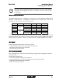
The following table describes the minimum and recommended requirement of the PC system to use a Web browser with our products. Item Minimal Recommended Mainboard/Chipset Intel 865 CPU P4 3.0GHz RAM 512MB D3D support Nvidia, ATI, VGA Intel built‐in graphic Memory : 64 MB OS Win 98, ME, XP, Vista Direct X 9.0 Rev1.0
Intel 945P Intel Core2Duo E4300 1GB D3D support ATI Radeon Series, Nvidia Geforce Series Memory : 128 MB Windows XP SP2 or higher 9.0 25
ZN-R1000E
Installation Manual
Webpage User's Manual
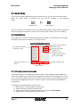
6.2. Basic Configuration
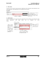
6.2.1. User management
The menus allowed to access may vary depending on your user group. The root user (ID: root, PW: pass) is authorized to all menus on the Setup page, and this default user is not removable. Beside the root user, you can add a user group. The user group is divided into two different levels: Operator and Administrator. Refer to the table below for details about accessible menus of each account. User Group Accessible Menu Operator Encoder Configuration Decoder Configuration Event Configuration Administrator All menus Limitation on user name A user name can contain from 1 to 14 characters with a combination of alphabet and numbers. Maximum of 32 accounts are available per an account group. Character range: All upper or lower case letters and the number from 0 to 9 Limitation on password A password can contain from 1 to 8 characters with a combination of alphabet and numbers. Character range: All upper or lower case letters and the number from 0 to 9 To have an authentication step before a user logs in, 1. Go to Setup > Basic Configuration > Users. 2. Select Enable. 3. Check the option box to allow all anonymous users for accessing the web page. If you want to request to enter ID and password even for entering the web page, skip to step 4. Uncheck the option box and click the Apply button to save the changes. To skip an authentication step before a user logs in to the Setup page, 1. Go to Setup > Basic Configuration > Users. 2. Select Disable. 3. Click the Apply button to save the changes. i
For an enhanced security, selecting the Enable option is recommended. Note Rev1.0
26
ZN-R1000E
Installation Manual
Webpage User's Manual
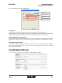
How to add a user
To add a user for the webpage, 1. Go to Setup > Basic Configuration > Users. 2. Click the Add button below the User List. 3. When the pop‐up window appears, type a user name and password. 4. Select the desired account level from Operator and Administrator. The Viewer account is not available. 5. Click the OK button to save the changes. 6. Check if the user name is added to the list. How to modify a user
To change your password or user group, 1. Go to Setup > Basic Configuration > Users. 2. On the User List, select the user name for changing the setting. 3. Click the Modify button below the User List. 4. When the pop‐up window appears, type a new password. If you want to change your user group only, skip to step 6. 5. Type the same password again on the text box of Confirm password. 6. Select the desired user group. 7. Click the OK button to save the changes. i
Note The user name is not allowed to be changed. If you want to modify the current user’s name, just remove it and add a new user. How to remove a user
To remove a user name form the User List, 1. Go Setup > Basic Configuration > Users. 2. Select the user name to remove on the User List. Rev1.0
27
ZN-R1000E
Installation Manual
Webpage User's Manual
3. Click the Remove button below the User List. 4. When the dialog box appears to confirm your request, click the OK button. 5. Check if the user name is removed from the list on the page. 6.2.2. Configuration of HTTP and HTTPS
To set the protocol for the product web server, go the Web Server page by clicking Setup > Basic Configuration > Web Server. The default web server setting the device is HTTP. If you want to change its setting to HTTPS to enhance its access security, select the HTTPS option. What is SSL? SSL is the abbreviation of Secure Socket Layer. SSL protects web server and makes it easy for users to trust the contents. When you use HTTPS for communication with server, the SSL certificate is required for the web server and the certificate enables encryption of video and audio data during online transactions. OpenSSL is one of the data security protocols for Linux system, which is used for the product. Setting the port number of web server To communicate with server by HTTP or HTTPS with TCP, the port number can be fixed between 1 and 65535. The factory default is set as 443. Redirecting HTTP to HTTPS: Even if a user tries to access the server with http, you can enable the server to be redirected to HTTPS. In this case, do not set ‘80’ for port number because it can cause a conflict with HTTP port. Cache Control To save the webpage loading time, you can use the cache control setting. If the content expiration mode is enabled, specific pages and images will be stored in client cache and be retrieved from it for one day. Once the mode is enabled, the resources in the cache are valid for one day even if you disable this feature. It is because the content expiration time is basically set to one day. Therefore, to avoid retrieving the resources from the cache, you should manually empty your cache. If the content expiration mode is not enabled, the cache Rev1.0
28
ZN-R1000E
Installation Manual
Webpage User's Manual
control may perform depending on the client PC environment, specifically your Internet Explorer option setting. Rev1.0
29
ZN-R1000E
Installation Manual
Webpage User's Manual
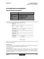
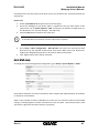
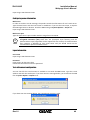
6.2.3. Setting date and time of device
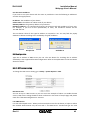
Time setting is very significant for all parts of the product server because it affects the log of streaming and burnt‐in text of video. To set the time, go to Setup > Basic Configuration > Date & Time. Every time you change the setting, the web server program of the product will be restarted internally. It may take more than a minute to restart. Display of current server time It shows the current server time with real time update. Selecting time zone You can choose your own time zone from the drop‐down box. If you check the ‘Automatically adjust for daylight saving time changes,’ it allows the daylight saving time to be applied according to your zone setting. Setting current time of server Select one of 3 options: •
•
•
Synchronize the server with your PC time Synchronize the server with NTP server via internet Set the server time manually by user Rev1.0
30
ZN-R1000E
Installation Manual
Webpage User's Manual
Periodical time synchronization NTP server – Server time is synchronized with NTP server. You can configure available NTP servers at Setup > System Options > NTP. Totally 4 of NTP servers can be added and the first one is set as the default server (ntp1.usv.ro). Real Time Clock on system – Server time is synchronized with Real‐time clock in the server. The clock is attached to the board of the product internally and the clock is recharged automatically when the server is started. Interval of synchronization Everyday 00:00 ‐ Synchronizes at every midnight Disabled – Synchronizes only when the decoder is rebooted (factory default) Rev1.0
31
ZN-R1000E
Installation Manual
Webpage User's Manual
6.3. Encoder Setting
To configure encoder channels on a display monitor that is connected to a decoder, go the Setup > Encoder Configuration > Connection. The channel connection mode is divided into two types: Instant and Preset. If you click on Instant or Preset#1~8, a pop up window appears to configure channels of an encoder to display. To configure video channels, refer to the following details about setting options. Preset name setup Unlike in the Instant mode setting window, the Friendly name option is added in the Preset mode. Since 8 different preset modes are supported, defining a certain preset mode with a promptly noticeable name would be helpful for users. Input the desired name on the text box of preset name for an easier recognition of the preset mode. Selecting a channel for configuration Select the tab of the desired channel number to configure. To display the channel, select the Enable check box. If you unselect the check box, the channel will not be displayed on the screen. Encoder Information Set the encoder information including the encoder type, session type, URL, and HTTP port. The encoder type includes three types as described on the table below. Type Description TYPE0 H.264 encoder TYPE1 MPEG4 encoder RTSP Connect via RTSP standard The RTSP type is generally for connecting a third party product. If you want to connect the standard encoders, that can be categorized by TYPE0 or TYPE1, with the RTSP type, make sure to check the encoder URL has been input correctly according to its session type (rtsp://hostname or ipaddress:[port]/[session name]). The HTTP port number is required only for the configuration of TYPE0 and TYPE1. i
Note Rev1.0
The audio out stream from the decoder to an encoder is only available when you select TYPE0 (H.264 encoder) for Encoder Type. TYPE1 or RTSP is not supported. 32
ZN-R1000E
Installation Manual
Webpage User's Manual
Login Information Enter the login information for the webpage of the encoder to connect. Encoder Channel & Stream Select the channel number of the encoder and its stream number. After the setup, click the Apply button on the bottom of the Encoder Setting window. And then go to the Connection Mode Setting page, select the mode to apply changes, and click the Apply button on the bottom. Rev1.0
33
ZN-R1000E
Installation Manual
Webpage User's Manual
6.4. Decoder Setting
6.4.1.View
To set up how to display videos on the screen, go to Setup > Decoder Configuration > Decoder. In this page, you can configure video display mode, screen margin, channel specification in display modes, etc. Refer to the following for more details. Checking video out format On the top of the page, you can check the current video out standard format. A user cannot change the format on the web page, but only by using the video output configuration switch on the decoder. Selecting display mode To specify how to display the video image on the default screen, select the desired mode on the View Mode option. In the Spot View mode, only one video is displayed on the screen. In the Quad View mode, the evenly split four‐windows appear on the screen. Spot mode setting Selecting the Spot mode will display the configuration options on the spot mode as below. Select the channel you want to display in a single view. If you want to enable PIP, then select the channel for PIP and defined its resolution and position. Afterward, check the Enable PIP box and click the Apply button on the bottom of the page. The Switch PIP button is activated only when the PIP mode is enabled. To switch the image that is displayed in the sub‐window with the full screen image, click the Switch PIP button. Quad mode setting Displaying all of the 4 channels in a view with high bitrate may be resulted in low quality images. If you want to keep the best quality for a specific channel while having too much DSP interference, give a priority on the channel by selecting its channel number on the following option. This option will be enabled only when you select the Quad mode. Rev1.0
34
ZN-R1000E
Installation Manual
Webpage User's Manual
Adjusting image margin The image margin can be adjusted on the web page. The adjusted margin will be displayed in black on the screen. Margin Left and right Top and bottom Supported value Multiplies of 16 up to 128 Multiplies of 4 up to 64 6.4.2. OSD
To configure how to display OSD menus on the screen, go to Setup > Decoder Configuration > OSD. The configurable OSD includes the IP address of connected encoder, shortcut icon, and FPS. Setting time to hide OSD You can set the time that OSD remains on the screen after stopping operations. If you set the OSD auto hide time to 3 seconds, the OSD will be disappeared on the screen 3 seconds after operation done. Setting this time to 0 will display the OSD all the time. Setting time for mouse cursor operation For the mouse cursor on the screen, you can set its time for being remained after operation done and its movement speed. If you set the auto hide time to 0, the cursor will be displayed on the screen all the time even though there is no movement of the cursor. For the best operation of your mouse on the screen, test its cursor movement speed and apply a suitable value. To test the cursor acceleration more clearly, jump the cursor to travel long distances. Setting the position of OSD The default position of OSD, which is IP address on left‐top, FPS on left‐bottom, and shortcut icon on right‐top, can be changed according your configuration. You can apply a different Rev1.0
35
ZN-R1000E
Installation Manual
Webpage User's Manual
setting for each channel and each view mode. If you want to put the OSD at a customized position other than the corners of screen, select normalized X,Y for the Predefined option and input the normalization value on the text box of X/Y. The normalization range of X and Y is from 0 to 9999. 6.4.3. Audio
The decoder supports two‐way mono audio. On the web page, you can configure the audio input volume and output channel or volume. Audio Output The compressed audio stream can be sent to H.264 encoder only. To enable the audio output from the decoder, select the Talk to the speakers of encoder channel check box and configure the desired volume level. If you connect a microphone on the device and prepare an encoder with a speaker, you can hear the input sound volume. Audio Input You to set the volume of capturing analogue audio generated at the camera installed site. After the configuration of Listen, you can listen to the sound with a speaker connected to the device. To listen to the captured sound, click the speaker (
) icon on the screen. If you uncheck the box of ‘Enable capture and compression audio,’ it will disable the server to capture the sound. i
Note The audio out stream from the decoder to an encoder is only available when you select TYPE0 (H.264 encoder) for Encoder Type. TYPE1 or RTSP is not supported. 6.5. Event Configuration
The products are equipped with the event server program internally and it enables you to configure the event publishers and subscribers. For instance, DI, DO, Network loss, and health of network server can publish the event message when an event is generated. How to move to each subscriber setting page Go to Setup > Event Configuration > DI, then the Publisher – DI page appears as below. Click each subscriber name such as DO and you can find that they are linked to the related setting pages. Refer to the figures of below for more specific information. Rev1.0
36
ZN-R1000E
Installation Manual
Webpage User's Manual
Setup ‐ IO Configuration ‐ DI/DO Multicast setting page Multicast setting page TCP setting page HTTP setting page 6.5.1. How to configure each event server
1. Email server You can use Email server to get the event notification from the device and send them to the client application by email. This page helps you to configure the Email server. Attaching a snapshot in an e‐mail is not supported. Automatically configured according to the setting page of [System Options – SMTP(email)]. Type the mail receivers, subject and contents of email 2. Multicast server You can use Multicast server to get the event notification from the device and send them to the client application. This page helps you to configure the Multicast server. Type a message name to show on event message program Type Address, port, and TTL according to your system setting. Factory default is 2555. Rev1.0
37
ZN-R1000E
Installation Manual
Webpage User's Manual
3. TCP server You can use TCP server to get the event notification from the device and send them to the client application. This page helps you to configure the TCP server. Type a message name to show on event message program Type port number according you will use for TCP message. Factory default is 2555. 4. HTTP server You can use HTTP server to get the event notification from the device and send them to the client application. This page helps you to configure the HTTP server.
*default: Original message format is shown (no parsed data) *customer0: You can customize the message format by configuring it with HTTP CGI and parameters. Type a message name to show. Type IP address and port of HTTP server
Type the desired waiting time from HTTP server until the response is arrived. Rev1.0
38
ZN-R1000E
Installation Manual
Webpage User's Manual
6.5.2. Assigning event rule to event publishers
Supported subscribers per each publisher:
Publishers DI DO Video Motion Detection VCA Network Health Subscribers DO, Email, Multicast, TCP, HTTP Email, Multicast, TCP, HTTP Email, Multicast, TCP, HTTP, Email, Multicast, TCP, HTTP DO, Email, Multicast, TCP Email, Multicast, TCP Multicast, TCP The below is an example page of DI event configuration. For each event server setting, refer to the section 6.4.1. How to configure each event server. When you set DI as a publisher, DO, Email, Multicast, TCP, and HTTP server can be the subscriber of DI triggering. Subscriber – DO Check the DO box you want to trigger and click Apply button. For example, if you check off the DO #1 of DI #2 => when DI #1 is detected, DO#2 will be activated. Subscriber – Email If you check ‘Post notification message,’ and click Apply button, the server will send the notification message by e‐mail to the client when DI detection is occurred. [System Option ‐ SMTP] and email account must be configured to activate this function. Attaching a snapshot on an email is not available. Rev1.0
39
ZN-R1000E
Installation Manual
Webpage User's Manual
Subscriber – Multicast If you check ‘Post notification message’ and click Apply button, the server will send the notification message via Multicast server when DI detection is occurred. Multicast server must be configured to activate this function by clicking the link button (Multicast). Subscriber ‐ TCP If you check ‘Post notification message’ and click Apply button, the server will send the notification message via TCP server when DI detection is occurred. TCP server must be configured to activate this function by clicking the link button (TCP). Subscriber ‐ HTTP If you check ‘Post notification message’ and click Apply button, the server will send the notification message via HTTP server when DI detection is occurred. HTTP server must be configured to activate this function by clicking the link button (HTTP). If you have finished to configure the event server and required subscribers, click Apply button for the application. Rev1.0
40
ZN-R1000E
Installation Manual
Webpage User's Manual
6.6. SYSTEM OPTION
6.6.1. TCP/IP (DHCP, Static IP, DNS setup) setup
To change the TCP/IP setting, go to Setup > System Options > TCP/IP. IP Address Configuration
Obtain IP address via DHCP If you want to get your IP from DHCP server automatically, check this option and click the Apply button. You may find the message box of below is popped up. It explains that the DHCP server in your router device may cause a problem and fail to lease new IP address. In that case, the latest static IP address will be applied instead. Click OK button to accept the notification. Rev1.0
41
ZN-R1000E
Installation Manual
Webpage User's Manual
Use the static IP address If you want to use your device with the static IP, enable the ‘Use the following IP addresses’ and click the Apply button. IP address: The IP address of your device Subnet mask: The address of subnet mask of your device. Gateway address: The gateway address of your device. Broadcast address: It is automatically fixed by the subnet mask and IP address of your own. For example, if you use B class (255.255.0.0) of mask, the broadcast address will be 192.168.255.255. The test button shows if the typed IP address is occupied or not. You may find the popup windows as below according to the availability of typed IP address. Occupied IP Available IP DNS Configuration
Type the IP address of DNS server you use. The test button for checking the IP address availability is also supported for DNS configuration. Refer to the explanation for the test button above for details. 6.6.2. NTP server setup
To change the NTP service setting, go to Setup > System Options > NTP. NTP Server Lists You can set up to 4 NTP servers as you can see at the example of above. To enable the NTP servers, DNS server setting should be done in advance in the menu of TCP/IP page and please check out if the DNS configuration is accurate. I am SNTP Server It is also called ‘Squid server.’ When you have multiple servers for the device, it helps to reduce the network load because only the one with ‘I am SNTP Server’ checked will get the time Rev1.0
42
ZN-R1000E
Installation Manual
Webpage User's Manual
information from the NTP servers and other servers for the device are synchronized with this Squid server. How to use: 1. Enable I am SNTP server of squid server and click Apply. 2. Access the webpage of the device which is supposed to be the client device of the squid server. Go to System Options > NTP and type the IP address of squid server on the ‘NTP Server 1s’t. (Format example : 192.168.11.4) 3. Click the Test button to find out if it works fine. i
It will take about 3~4 minutes until the squid server response. Note 4. Go to Setup > Basic Configuration > Date & Time and choose the ‘Synchronize with NTP server’ for the method of New Server Time menu. Make sure if the ‘NTP Server’ displays the designated squid server’s IP correctly with red characters. 5. Click ‘Apply’ button and it will be restarted. 6.6.3. UPnP setup
To change the Universal Plug & Play configuration, go to Setup > System Options > UPnP. UPnP allows IP devices to connect seamlessly, and to simplify the implementation of networks in remote PC environments. Refer to the example of UPnP of Windows XP so that you can check out how the customized settings are being applied. Find this information on your PC [Start ‐ My network places]. Find your device, right‐click the mouse and go to [property]. Rev1.0
43
ZN-R1000E
Installation Manual
Webpage User's Manual
e.g. Customized UPnP name and description Friendly name Manufacturer name Model name Decoder
Model description Configuration If you want to enable UPnP to search your device, check the box of ‘Enable UPnP’. Friendly Name: Type any friendly name to be shown by the UPnP program. You can test it easily with Windows as well (Start ‐ My network Places displays the devices by UPnP). Customize Manufacturer Description If you want to have your own manufacturer’s name for the device to be shown on the UPnP program, type name and URL. Then, The UPnP program will show the modified name and URL. Customize Model Description If you want to have your own model name for the device to be shown on the UPnP program, type name, description and URL of them. Then, The UPnP program will show the modified name, description and URL. 6.6.4. mDNS (Multicast DNS) setup
For the multicast DNS setting, go to Setup > System Options > mDNS. Rev1.0
44
ZN-R1000E
Installation Manual
Webpage User's Manual
If you have your own program or device which is required to use the mDNS, this page helps you to customize the name of model and manufacturer instead of factory default. Configuration If you check the box of ‘Enable,’ mDNS is activated. You can type the Friendly Name to be shown on the application program. Customize Manufacturer Description You can type the manufacturer’s name and home URL of your device. The given company name is typed as a default for the name but it is adjustable as you want. Customize Model Description You can type the model name, description of the model and URL of your device. ‘ENC’ is typed as a default for the name but it is adjustable as you want. 6.6.5. SMTP setup
To change the SMTP setting, go to Setup > System Options > SMTP(email). You can set the user’s mail account and server to apply this SMTP for event or any other SMTP required purpose. Configuring user information
Unit Name Type the friendly name for the product server to show on e‐mail and it helps you to distinguish the devices from other devices when you use multiple network video servers. Input range: 40 characters limit From email address Type the e‐mail address of a sender. Rev1.0
45
ZN-R1000E
Installation Manual
Webpage User's Manual
Input range: 128 characters limit Configuring server information
Mail server In order to send the e‐mail message, the product needs the information of user’s mail server. Type the Mail server with the host name or IP Address. If you use the host name, it requires the DNS registration in advance. Check the DNS setting on System Options > TCP/IP tab. Input range: 128 characters limit Mail server port Type the mail server’s port number with the range from 0 to 65535. If your email server requires encryption process of SSL and TLS, select the Enable encrypted connection (SSL) check box. TLS (Transport Layer Security) and SSL i
(Secure Sockets Layer) algorithm can be required for the security of communication Note over networks. It depends on your email server and you should check out the communication protocol of SMTP server. Logon Information
User name Input range: 128 characters limit Password Input range: 32 characters limit 8 asterisks cannot be used for the password. Test with current configuration
You can check if the e‐mail account is available or not with the test button. Type the e‐mail address and click the test button. If you have seen the message below, you should set the DNS first at System Option > TCP/IP menu. If you have seen the message below, the entered mail account is valid. Rev1.0
46
ZN-R1000E
Installation Manual
Webpage User's Manual
6.6.6. LED Setup
To change the LED setting, go to Setup > System Options > LED. You can customize the LED operation according to your system requirement. Please refer to the example scenario first. Example of configuration
Scenario : “When the video signal loss is detected, let top LED blink for every 5 seconds” Setting : Top Yellow ‐ Ticked Event Publisher ‐ vsignal Operation ‐ Blink Time Out – 5 Option – Turn on the LED of vsignal : Select ‘When video signal loss is detected.’ Basic configuration
1. Select the Enable LED check box to enables the LED function. 2. Select the event publisher you want to apply for the LEDs. 3. Select the operation type of each LED; Blink or On mode. 4. Select the time out value. 1 to 5 sec and permanent alarming are supported. i
Refer to 2.2.1 Front Panel for the location of LEDs on the device. Note Rev1.0
47
ZN-R1000E
Installation Manual
Webpage User's Manual
If you are configuring DSP load, temperate, and video signal loss?
The option page provides the configuration of DSP load, temperature change, and video loss. (1) Set the dspload limits to E.g. Setting the value as 90% ‐ While the DSP load keeps lower than 90%, the LED will operate as you configured at Location tab. (2) Set the temperature limits to E.g. Setting the min 0 and max 65 ‐ While the temperature is between 0 and 65, the LED will operate as you configured at Location tab. (3) Turn on the LED of Vsignal Select one of the options between ‘When video signal loss is detected’ and ‘When video signal is normal’. Then, the selected LED will operate when the selected condition is satisfied. (4) Turn on the LED of Heartbeat Select one of the options between ‘When heartbeat status is watchdog’ and ‘When heartbeat status is normal’. Then, the selected LED will operate when the selected condition is satisfied. 6.6.7. DDNS (Dynamic DNS)
To change the Dynamic DNS setting, go to Setup > System Options > DDNS and follow the procedures below. 1. Check the ‘Enable DDNS’ box. 2. Select the protocol type you want. i
DynDNS and Custom07 are installed on the device only. Note 3. Type the domain name you want to use for the product. 4. Type the update time. The factory default is 600 seconds and it enables the product notify the DDNS of the current domain name. 5. Type the user name and password of your DDNS account. Note that 8 asterisks cannot be used for the password. 6. Click the Apply button. Rev1.0
48
ZN-R1000E
Installation Manual
Webpage User's Manual
6.6.8. SNMP
To enable the remote management of IP devices, go to Setup > System Options > SNMP. The Simple Network Management Protocol (SNMP) is literally the protocol for managing network. By retrieving the system information, it allows to manage network architecture, performance, device, and security. To enable SNMP, select the Enable check box. The encoder supports SNMP version 2c and 3. SNMP information Input your SNMP information on the following section. For the Read Community, input the community name, which is the authorized ID for reading SNMP data. The factory default value is ‘public.’ Trap setting The Trap can be considered as sending an event message from an event publisher such as DIO and VCA. Choose the SNMP Trap version to receive Trap event, and input the IP address and community on the text box. i
For the details about SNMP MIB information, please contact our support team. Note Rev1.0
49
ZN-R1000E
Installation Manual
Webpage User's Manual
6.7. IO CONFIGURATION
6.7.1. DI/DO control
To set up DI/DO and UART, go to Setup > IO Configuration > DI/DO. In case of using additional device such as alarm system or sensor system, you can configure the DI (Digital Input) and DO (Digital Out) in this page. DI Resource Type
You can choose the DI resource type, RELAY or VOLTAGE (The maximum is 5V). DI & DO Status
It reflects the current states of actual DI and DO. 2 of DI and DO are supported on the device. To understand DI/DO status options, refer to the following scenario. Scenario When it’s assumed that DI#1 and DO#1 are coupled by event system. The DI#1 trigger type is Normal Open. Suddenly DI#1 is triggered by any kind of event. Expected Response – The status of DO#1 will be changed from OFF to ON, if the default setting is OFF. The status of DI#1 will be changed from OPEN to CLOSE. Rev1.0
50
ZN-R1000E
Installation Manual
Webpage User's Manual
DO Control
If you want to test DO operation manually on the webpage, click the soft buttons of OFF and ON. Then, you can see that how DO works. These commands also affects the ‘DO status’ because the ‘DO status’ shows the current status of DO. Friendly Name
You can type any friendly name for DI and DO. This setting helps you to identify which DI or DO is activated especially when you have multiple product servers on your application program. DI Trigger Type
You can select the trigger type between normal open (NO) and normal close (NC). DI Re-arm Period
Use this option to set up detection time interval for event publishers. For example, if you input ‘0,’ it generates events all the time whenever DI is detected. But if you input ’10,’ only 1 event will be triggered for 10 seconds even if multiple DIs are detected for this 10 seconds. DO Hold period
The DO Hold Period indicates for how long does the DO works. For example, if you input ‘0,’ a DO device keeps working until a user turns it off manually. If you input ’10,’ a DO device will work for 10 seconds and finish the operation. However, if you turn a DO device on manually by using the DO Control button, it will be activated without being affected by the DO hold period unless you click the OFF button. Rev1.0
51
ZN-R1000E
Installation Manual
Webpage User's Manual
6.7.2. UART setting for serial device
For the USRT setting, go to Setup > IO Configuration > UART. The UART setup is supported with two different pages: UART1 and UART2. For the RS485 port, use the UART1 setup page. For the RS232C port, use the UART2 setup page. UART type
Internal PTZ: Used when you connect a PTZ camera to an encoder. RS485 is for UART1 and RS232 is for UART2. AUX: Used when you connect an auxiliary device that requires serial communication to an encoder. RS485 is for UART1 and RS232 is for UART2. SerialOverIP: Used to enable the communication for the devices connected to the serial ports of an encoder Rev1.0
52
ZN-R1000E
Installation Manual
Webpage User's Manual
Why distinguish between PTZ and AUX? When the PTZ type is selected, the required PTZ protocol and the control daemon are run and assigned to the serial communication internally. External When 3rd party program is added to the server side of the encoder and this add‐on program needs to control the attached serial devices, you should select the external option. So, if you do not use any serial control program, you can ignore this option. SerialOverIP
This section is enabled only when you select SerialOverIP for the UART type. Select the desired communication mode: UDP, TCP Client, or TCP Server. And type the IP address of client and port number on the text box of SerialOverIP section. You can check the communication status from the client PC by using a related freeware. If you run the program and connect to a device via its IP address and port number, you can see that the data transferred from the port has been received at UART1. You must distinguish this option from the general concept of SerialOverIP, which allows controlling the devices connected to a serial port of the IP device, by using i
HTTP API commands. For the information of this commands, refer to ZN‐R1000E Note HTTP API Manual.pdf. PTZ Protocol
PTZ Name : You need to set the UART type as RS485‐PTZ before selecting the PTZ protocol. If you click the drop down box of PTZ name, the available protocols are listed. Choose the required protocol to communicate with your camera. PTZ Address : Type the PTZ address as you have set on your PTZ camera. You may find the dip switch at the bottom of the PTZ camera which enables the cameras to have their own address. Refer to your PTZ camera hardware manual for the PTZ address setting. Serial port setup
These settings are necessary when you want your serial device to be communicated with the encoder or IP camera. The default values of web page are set for the RS485 PTZ device but you can set the values according to your own device requirement. Rev1.0
53
ZN-R1000E
Installation Manual
Webpage User's Manual
6.8. MAINTENANCE
6.8.1. Firmware update port setup
Firmware update is allowed only by the IPAdminTool.exe, which is provided in the SDK (\BIN\TOOLS\AdminTool vX.X.X.X). Refer to the IPADminTool User’s Manual.pdf to find out how to update the firmware on your devices. Before you upload the firmware with IPAdminTool.exe, go to Setup > Maintenance > Firmware Update. Then, select the Enable Firmware Update check box and set the port number. If you remove the check from this box, updating the firmware is not allowed. 6.8.2. Getting system Log
In order to get the system log of the product, please follow the steps of below. 1. Go to Setup > Maintenance > System Log. 2. Check the Enable System Log box. 3. Type max size of file between 32KB and 200KB. Then, the log files will be created according to the fixed size (Up to 5 files are created and the oldest file will be replaced by the latest file). 4. Click the Apply button and then the log file will be created. If you want to see the log list, click the LOG LIST button. Name : The log files are named automatically. It’s not allowed for user to name it manually. Size : Log file size is updated in real time. Latest access time : Latest time when the product accessed the internal system to get the log. Displays the files created Rev1.0
54
ZN-R1000E
Installation Manual
Webpage User's Manual
6.9. ABOUT
To find the product information including the hardware specification and software version, go to the About page by selecting Setup > About. This menu is configured with two sub menus: Version and Licenses. 6.9.1. Version
On the Version page, you can find the information about the current firmware version on the top of the page. Other detailed information for its hardware and software configuration is found in this page as well. Refer to the following list for the provided information. Hardware MAC address Microprocessor Bootloader Kernel Root filesystem APP filesystem Webpage ActiveX SSSDK HTTP‐API VCA Tracker ufs Language Video‐in Video‐out Audio‐in Audio‐out DI/DO UART#1 UART#2 USB PoE SD slot Day & Night Rack information 6.9.2. Licenses
On the Licenses page, the information for the third party software license that has been used on the development of the device is displayed. Rev1.0
55
ZN-R1000E
Installation Manual
Webpage User's Manual
APPENDIX (A): SPECIFICATIONS
Summary
Video Input N/A Output 1 analog output Supported encoder device ZN‐Sxxxx/ZN‐RSxxxx/ZN‐DxxxxVxE/ZN‐DxxxxAxE ZN‐YxxVxE/ZN‐NxxVxE Decompression Format H.264, MPEG‐4, MJPEG Resolution D1 Compression FPS 25/30 fps@D1 (PAL/NTSC) Megapixel is not supported OSD Supported Video Output Configuration Switch Supported Audio Input/output 1/1 channel Compression Format G.711 Function Digital Input/output 2/2 channel RS‐485 Supported RS‐232 Supported Network 100 Base‐T Power over Ethernet Supported Protocol TCP/IP, UDP/IP, HTTP, RTSP, RTCP, RTP/UDP, RTP/TCP, SNTP, mDNS, UPnP, SMTP, SOCK, IGMP, DHCP, DDNS, SSL v2/v3, IEEE 802.1X, SSH (TBD) USB 2.0 Supported for USB mouse SD Memory N/A Dimensions 103(W) x 38(H) x 141(D) mm Electrical Characteristics
Video Input Video Output Audio Input Audio Output Sensor(D/I) Alarm(D/O) Power Source(Approx) Rev1.0
1Vp‐p, 75Ω 1Vp‐p, 75Ω Linein, 1.43Vp‐p(Min 1.35Vp‐p, max 1.49 Vp‐p), 39 KΩ Lineout, 46mW Power, 16 Ω TTL level 4.5V threshold, Max 50mA Max 500mA@24VAC or 1A@12VDC DC 12V / PoE IEEE802.3af (Class 0) 56
ZN-R1000E
Power Cosumption (With mouse connected) Installation Manual
Webpage User's Manual
3W (DC12V) / 3.84W (PoE) Environment Condition
Operating Temperature Operating Humidity 0 ºC ~ 60 ºC (32 ºF ~ 140 ºF) Up to 85% RH Mechanical Condition
Color Dimension Weight (Approx) Black 103(W) x 38(H) x 141(D) mm 385g Rev1.0
57
ZN-R1000E
Installation Manual
Webpage User's Manual
APPENDIX (B): POWER OVER ETHERNET
The Power over Ethernet (PoE) is designed to extract power from a conventional twisted pair Category 5 Ethernet cable, conforming to the IEEE 802.3af Power‐over‐Ethernet (PoE) standard. IEEE 802.3af allows for two power options for Category 5 cables. The PoE module signature and control circuit provides the PoE compatibility signature and power classification required by the Power Sourcing Equipment (PSE) before applying up to 15W power to the port. The high efficiency DC/DC converter operates over a wide input voltage range and provides a regulated low ripple and low noise output. The DC/DC converter also has built‐in overload and short‐circuit output protection. Note: For proper activation of 12V PoE, the Category 5 cable must be shorter than 140m and conform the PoE standard. PoE compatibility
With non Power Sourcing Equipment (PSE) When it is connected with non PSE, the power adaptor should be connected. With power adaptor Connecting both PSE and power adaptor does not do any harm to the products. Disconnecting power adaptor while it is operating does not stop operation. The product continues to work without rebooting. Power classification
The PoE Power Class supported by the IP device is Class 0. Class Usage Minimum Power Levels Output at the PSE 0 Default 15.4W Maximum Power Levels at the Powered Device 0.44 to 12.95W Rev1.0
58
ZN-R1000E
Installation Manual
Webpage User's Manual
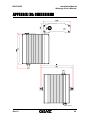
APPENDIX (C): DIMENSIONS
(Unit: mm) Rev1.0
59
ZN-R1000E
Installation Manual
Webpage User's Manual
REVISION HISTORY
MANUAL# D1A.00 D1A.00 01A.00 DATE (M/D/Y) 05/28/10 09/03/10 11/24/10 COMMENTS Created Preliminary version for DP sample Initial version Rev1.0
60