1
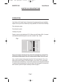
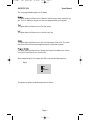
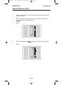
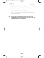
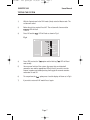
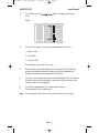
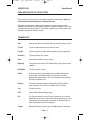
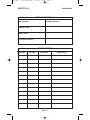
350 USER Cover 2.qxd
26/06/2006
15:30
Page 2
G a r d Te c
3 5 0 + C o n t r o l Pa n e l
User Instructions
350 USER - inst quark.QXD
12/10/02
20:12
Page 1
Users Manual
GARDTEC 350
Contents
Introduction
1
Setting the System
Part Setting the System
Unsetting the System
Resetting after an Alarm
2
2
3
3
User Programming Mode
3
Removing Individual Zones
5
Testing the System
7
Reading the Log
8
Turning Chime On and Off
9
Programming User Codes
11
Care and Service of Your System
13
Terminology
13
Installers Details
14
Service Record
14
350 USER - inst quark.QXD
12/10/02
20:12
Page 2
Users Manual
GARDTEC 350
GARDTEC 350 USER INSTRUCTIONS
INTRODUCTION
Your Gardtec 350 Control Panel will have been fully programmed by your installation
engineer to suit your needs. Normal day to day operations will consist of the following:Fully setting the system
Part setting the system
Unsetting the system
Display is given via eight individual L.E.Ds. When using the Gardtec 350 in it’s normal
user mode the bold black legend is used, this is shown in Fig 1. below.
Fig 1.
300 Series
GARDTEC
POWER
DAY
Z1
Z2
Z3
Z4
Z5
TAMPER
REMOVE
TEST
LOG
CHIME
PROGRAM
ENTER
A key press tamper will activate if more than 24 invalid digits are entered. This
will cause an internal alarm if the unit is unset and a full alarm if the unit is set.
Keys 1 and 3 have been factory programmed for P.A (Personal Attack). This is a 24
hour function and will operate if the control panel is set or unset. To use the keypad
P.A function press and hold keys 1 and 3 at the same time, the alarm will then activate.
To stop the alarm sounding enter a valid user code. After the keypad P.A function has
been used the system will require resetting as shown on page 3.
Page 1
350 USER - inst quark.QXD
12/10/02
20:12
Page 3
Users Manual
GARDTEC 350
SETTING THE SYSTEM
To Fully Set the system proceed as follows:1)
Enter a valid User code.
(The DAY LED will flash followed by the exit tone.
Any zones violated during exit will change the
exit tone and the appropriate L.E.D will indicate).
2)
Leave the premises via the
authorised exit route.
Note:
To abort setting during exit time re-enter the code.
PART SETTING THE SYSTEM
To Part Set the system proceed as follows:1)
Enter a valid User code.
(The DAY LED will flash followed by the
exit tone).
2)
If Part Set 1 is required Press 1 or
(The DAY LED will flash slowly. Zones
programmed as Part 1 will be removed)
If Part Set 2 is required Press 2 or
(The DAY LED will flash slowly. Zones
programmed as Part 2 will be removed)
If Part Set 3 is required Press 3
(The DAY LED will flash slowly. Zones
programmed as Part 1 and Part 2 will
be removed).
3)
Leave the premises via the authorised exit route (or retire to an unprotected
area).
Note:
If any of the above part sets have been programmed as silent by your
engineer the setting will be silent with a single beep as the system finally sets.
Page 2
350 USER - inst quark.QXD
12/10/02
20:12
Page 4
Users Manual
GARDTEC 350
UNSETTING THE SYSTEM
To Unset the system proceed as follows:1)
Enter the premises via an authorised entry point (the entry tone will sound).
2)
Proceed directly to the Control Panel and enter a valid User code (the entry
tone will stop and the DAY LED will illuminate).
3)
If the alarm has been activated during the set period all the LEDs will flash
press NO to view the cause of alarm.
RESETTING AFTER AN ALARM
If the system is set, unset it as shown above and proceed as follows:1)
After an alarm all the LEDs will be flashing. If you wish to view the cause of
alarm press NO. To Reset the system enter the Master code and start to set
the system.
2)
Before the entry time expires enter a valid code to abort the setting. The
system is now reset.
USER PROGRAMMING MODE
To enhance the flexibility of the Gardtec 350 Control Panel there are five user programmable options available. When programming the User options the display is via
the five Zone L.E.Ds and the White legend is used. This is shown in Fig 2. below. It
should be noted the the user programming mode is only available to the Master user
(User 1).
Fig 2.
300 Series
GARDTEC
POWER
DAY
Z1
Z2
Z3
Z4
Z5
TAMPER
Page 3
REMOVE
TEST
LOG
CHIME
PROGRAM
ENTER
350 USER - inst quark.QXD
12/10/02
20:12
Page 5
Users Manual
GARDTEC 350
The User programmable options are as follows:-
Remove
This option enables the Master user to Remove individual zones when setting the system. This is in addition to any part set suites pre-programmed by your engineer.
Test
This option allows the Master user to Test the system.
Log
This option allows the Master user to view the event Log.
Chime
This option allows the Master user to turn the Chime option On and Off. (The zones
that are on chime will have been programmed by the installation engineer).
Program (Code)
This option allows the Master user to change the Codes for the Master user (User1),
User (User2) and Set only user (User3) levels.
When programming the User options the LEDs may show the following status:Fig 3.
OFF
ON
FLASHING
To program the options shown above proceed as follows:-
Page 4
350 USER - inst quark.QXD
12/10/02
20:12
Page 6
Users Manual
GARDTEC 350
REMOVING INDIVIDUAL ZONES
1)
With the Control panel in the DAY mode (Unset) enter the Master code. The
exit tone will sound.
2)
Before the exit time expires Press NO. The exit tone will silence and the
R e m o v e LED will flash as shown in Fig 4.
Fig 4.
300 Series
GARDTEC
3)
POWER
DAY
Z1
Z2
Z3
Z4
Z5
TAMPER
REMOVE
TEST
LOG
CHIME
PROGRAM
ENTER
Press YES to program the R e m o v e option. The display will show as Fig 5.
Fig 5.
300 Series
GARDTEC
POWER
DAY
Z1
Z2
Z3
Z4
Z5
TAMPER
Page 5
REMOVE
TEST
LOG
CHIME
PROGRAM
ENTER
350 USER - inst quark.QXD
12/10/02
20:12
Page 7
Users Manual
GARDTEC 350
4)
Press the key corresponding to the zone you wish to remove followed by the
YES key (a comfort tone will be generated if all is okay). If you make a mistake and remove the wrong zone repeat the operation from step 3 but press
NO after the zone number.
5)
If you wish to remove more zones repeat from step 3.
6)
When you have finished removing the required zone(s) press the 0 key to
escape programming mode.
Note:
This operation should be carried out each time you wish to remove
individual zones. If you remove the same zone(s) on a regular basis ask
your engineer to put them in a part set suite.
Page 6
350 USER - inst quark.QXD
12/10/02
20:12
Page 8
Users Manual
GARDTEC 350
TESTING THE SYSTEM
1)
With the Control panel in the DAY mode (Unset) enter the Master code. The
exit tone will sound.
2)
Before the exit time expires Press NO. The exit tone will silence and the
R e m o v e LED will flash.
3)
Press NO and the T e s t LED will flash as shown in Fig 6.
Fig 6.
300 Series
GARDTEC
POWER
DAY
Z1
Z2
Z3
Z4
Z5
TAMPER
REMOVE
TEST
LOG
CHIME
PROGRAM
ENTER
4)
Press YES to select the T e s t option and the flashing T e s t LED will illuminate steadily.
5)
You may now "walk test" the system. Any zones that are violated will
generate a tone and the appropriate LED will flash. If you wish to test the
external sounders and strobe pressing 9 will toggle the external sounders
and strobe On and Off.
6)
To escape from the T e s t option press 0 and the display will show as in Fig 6.
7)
If you wish to return to DAY mode Press 0 again.
Page 7
350 USER - inst quark.QXD
12/10/02
20:12
Page 9
Users Manual
GARDTEC 350
LOG
The Gardtec 350 has a 50 event Log that records system events in the order that they
occur. To view the Log proceed as follows:-
1)
With the Control panel in the DAY mode (Unset) enter the Master code. The
exit tone will sound.
2)
Before the exit time expires Press NO. The exit tone will silence and the
R e m o v e LED will flash.
3)
Press NO Twice and the L o g LED will flash as shown in Fig 7.
Fig 7.
300 Series
GARDTEC
POWER
DAY
Z1
Z2
Z3
Z4
Z5
TAMPER
REMOVE
TEST
LOG
CHIME
PROGRAM
ENTER
4)
Press YES to use the L o g option. The display shown is the last event. To
view the previous event press NO, to move to the next event press YES.
5)
To escape out of the L o g option press 0 and the display will show as in Fig 7.
6)
If you wish to return to DAY mode press 0 again.
Whilst in the L o g mode the LEDs may display the following:All LEDs on indicates an alarm, press NO to view the cause.
DAY LED with Z1, Z2 or Z3 LEDs indicate unset by user 1, 2 or 3
Rapid flashing DAY LED. System was Set. Slow flashing DAY LED System was Part
set
If all the LEDs are flashing this indicates an alarm occurred. Pressing NO to move to
the previous event will show the cause of alarm
If the zone LED(s) are illuminated without the alarm indication the zone was removed.
Page 8
350 USER - inst quark.QXD
12/10/02
20:12
Page 10
Users Manual
GARDTEC 350
CHIME
The Chime function may be turned On or Off by the Master user. Before Chime can be
turned on the Chime zones should have been programmed by your engineer.
To turn the Chime On or Off proceed as follows:-
1)
With the Control panel in the DAY mode (Unset) enter the Master code. The
exit tone will sound.
2)
Before the exit time expires Press NO. The exit tone will silence and the
R e m o v e LED will flash.
3)
Press NO Three times and the C h i m e LED will flash as shown in Fig 8.
Fig 8.
300 Series
GARDTEC
4)
POWER
DAY
Z1
Z2
Z3
Z4
Z5
TAMPER
REMOVE
TEST
LOG
CHIME
PROGRAM
ENTER
Press YES to change the status of the C h i m e. The Display will show as Fig 9.
Fig 9.
300 Series
GARDTEC
POWER
DAY
Z1
Z2
Z3
Z4
Z5
TAMPER
Page 9
REMOVE
TEST
LOG
CHIME
PROGRAM
ENTER
350 USER_Page Updates.qxd
12/10/02
20:15
Page 1
Users Manual
GARDTEC 350
USER CODES
When programming User Codes you should note the following:a)
User 1 is always the Master Code. This level of code allows you to perform all
User functions (including resetting after an alarm) and all User Programming
functions. The Master Code may be changed by the Master User but it may
not be deleted.
b)
User 2,6,7 & 8 are always User level. This level of code will allow you to Set,
Part Set and Unset the system. If you wish to delete the code enter 0000
when asked to enter the code during programming.
c)
User 3 & 9 are Set only level. This level will allow you to Set and Part Set the
system only. If you wish to delete this code enter 0000 when asked to enter
the code during programming.
To program the user codes proceed as follows:1)
With the Control panel in the DAY mode (Unset) enter the Master code. The
exit tone will sound.
2)
Before the exit time expires Press NO. The exit tone will silence and the
R e m o v e LED will flash.
3)
Press NO Four times and the Program LED will flash as Fig 10.
Fig 10.
300 Series
GARDTEC
POWER
DAY
Z1
Z2
Z3
Z4
Z5
TAMPER
Page 10
REMOVE
TEST
LOG
CHIME
PROGRAM
ENTER
350 USER_Page Updates.qxd
12/10/02
20:15
Page 2
Users Manual
GARDTEC 350
4)
Press YES to use the P r o g r a m (C
C o d e) option. The display will show as
Fig 11
Fig 11.
300 Series
GARDTEC
5)
POWER
DAY
Z1
Z2
Z3
Z4
Z5
TAMPER
REMOVE
TEST
LOG
CHIME
PROGRAM
ENTER
Enter the User number you wish to program followed by YES from:1 = Master Code Level
2 = User Code Level
3 = Set Only Code Level
4 = Master Code Level
5 = Master Code Level
6 = User Code Level
7 = User Code Level
8 = User Code Level
9 = Set Only Level
A comfort tone is generated if all is okay
6)
Enter a new four digit code followed by YES (entering 0000 will delete the
present code, however the Master code may only be changed and not
deleted). A comfort tone will be generated if all is okay.
7)
Enter the same four digit code again to confirm followed by YES. (If a mistake
has been made and no comfort tone is generated or if the two codes do not
match the code will not be updated.
8)
If you wish to program other user codes repeat from step 4
To escape back to DAY mode press 0.
Note:
Any of the digits 0-9 may be used any number of times in a user code.
Page 11
350 USER - inst quark.QXD
12/10/02
20:13
Page 13
Users Manual
GARDTEC 350
4)
Press YES to use the P r o g r a m (C
C o d e) option. The display will show as
Fig 11
Fig 11.
300 Series
GARDTEC
5)
POWER
DAY
Z1
Z2
Z3
Z4
Z5
TAMPER
REMOVE
TEST
LOG
CHIME
PROGRAM
ENTER
Enter the User number you wish to program followed by YES from:1 = Master Code
2 = User Code
3 = Set Only Code
A comfort tone is generated if all is okay
6)
Enter a new four digit code followed by YES (entering 0000 will delete the
present code, however the Master code may only be changed and not
deleted). A comfort tone will be generated if all is okay.
7)
Enter the same four digit code again to confirm followed by YES. (If a mistake
has been made and no comfort tone is generated or if the two codes do not
match the code will not be updated.
8)
If you wish to program other user codes repeat from step 4
To escape back to DAY mode press 0.
Note:
Any of the digits 0-9 may be used any number of times in a user code.
Page 12
350 USER - inst quark.QXD
12/10/02
20:13
Page 14
Users Manual
GARDTEC 350
CARE AND SERVICE OF YOUR SYSTEM
User care of the system consists of occasionally wiping the control panel. Under no
circumstances should detergents or abrasives be used.
Opening the control panel or detectors will generate a tamper alarm and service
should be carried out by a qualified alarm engineer. It may be a condition of your insurance policy that your alarm system is serviced on a regular basis. Please contact your
installation company for details of service.
TERMINOLOGY
User
A person who will use the control panel (e.g turn the alarm on or off).
Full Set
To turn all protected areas on ie to arm all areas.
Part Set
To set the system leaving a group or groups of areas unprotected.
Unsetting
To turn off (disarm) the system.
Zone
An area protected by the alarm system.
Resetting
To restore back to normal DAY mode display usually after an alarm
condition.
DAY Mode
The alarm system is unset.
Chime
A chime zone that is activated will give an audible tone from the
control panel. It should be noted that chime zones need to be
programmed by the engineer. The chime function may be turned on
and off by the Master user.
Remove
The remove function allows the system to be set with individual
zones removed. This function is in addition to any Part Sets.
Log
A history of events.
LED
Light Emitting Diode (indicating lamp).
P.A
P.A (Personal Attack) is active 24 hours irrespective of the control
panel being set or unset. It may be activated by pressing keys 1 and
3 together on the control panel or activating a P.A button that has
been allocated to a zone by the engineer.
Tamper
Monitored 24 hours a day will give an audible warning if activated.
Page 13
350 USER - inst quark.QXD
12/10/02
20:13
Page 15
Users Manual
GARDTEC 350
INSTALLATION DETAILS
Company Name:-
Company Address:-
Company Tel No:-
Service Tel No:-
First Service Due Date:-
SERVICE RECORD
Service No
Due Date
Actual Date
1
2
3
4
5
6
7
8
9
10
11
12
13
Page 14
Engineers Sig
Test.qxd
26/06/2006
GARDTEC 350
Notes
15:40
Page 33
User Manual
Test.qxd
26/06/2006
GARDTEC 350
Notes
15:40
Page 33
User Manual
Test.qxd
26/06/2006
GARDTEC 350
Notes
15:40
Page 33
User Manual
350 USER Cover 2.qxd
26/06/2006
15:30
Page 1
RISCO Group UK Ltd
Tel: 0161 655 5500 Fax: 0161 655 5501
Internet: www.riscogroup.com
e-mail: [email protected]
Technical Support: 0161 655 5600
Technical Support Fax: 0161 655 5610
RISCO Group UK Ltd reserve the right to amend the software and features without prior notice
PR2897 REV2.3