1
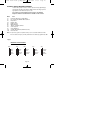
PR5846 Rev12 490X QS Eng.qxd
10/05/2012
11:38
Page 1
GT490X
Control Panel
Quick Start Instructions
Download the complete GT490X Engneer’s Ref. Guide at
www.riscogroup.co.uk
RISCO Group UK Ltd
Tel: 0161 655 5500 Fax: 0161 655 5501
Int Tel: +44 161 655 5500 Fax: +44 161 655 5501
Internet: www.riscogroup.co.uk
e-mail: [email protected]
Technical Support Tel: 0161 655 5600
Technical Support Fax: 0161 655 5610
(Mon - Fri 08:30-1730)
This Quick Start Guide gives brief installation information for the GT490X
Control Panel. RISCO Group UK Ltd reserve the right to amend the software and features
without prior notice.
5IN490IMQ C
PR5846 Rev1.2
PR5846 Rev12 490X QS Eng.qxd
10/05/2012
11:38
Page 2
IMPORTANT!
Input: GT490X
Nominal Temp Range:
Humidity
AC230V +/-10% ~50Hz 125mA Max. 35W Max
0 - 50°C
70% non condensing
GT490X Metal
For Indoor Use Only
This equipment is intended only for use as a Security Alarm Control Panel. Adequate
ventilation away from heat and humidity must be provided. The unit must be fixed
securely to a non-flammable surface using suitable fixings.
All mains wiring must conform to the relevant current IEEE wiring regulations (or
appropriate international regulatory standards). See Mains Supply Connection section
within this manual for more detailed instructions.
All wiring must be protected from sharp or jagged edges.
All Low voltage (alarm) wiring must be to the appropriate international regulatory
standards and comply to good wiring practice and should be routed away from the
mains cables.
Replacement fuses should be of the same type and rating conforming to IEC 127.
The GT490X Control Panel is fitted with resettable fuses. The areas protected are
Battery, Aux and Keypad. In the event of a fuse tripping or an input/ output not
working, remove the source of the load and check wiring for shorts. Check any added
devices for full functionality before any reconnection.
The maximum current draw from the unit for all output combinations must not exceed
the rated output.
The unit is intended for use with a suitable re-chargeable lead acid battery
permanently connected to the appropriate terminals.
All documentation and manuals must be thoroughly read by suitably qualified
installation personnel prior to installation.
Important Safety Information. Hazardous Voltages Inside,The unit has no user
serviceable parts inside. No User Access. Internal access should only be by
suitably qualified personnel.
GT490X Metal
The unit MUST be Earthed. It is the responsibility of the installation engineer to
ensure that the earth connection to the unit lid is good on completion of the installation
or after service.
Page 1
PR5846 Rev12 490X QS Eng.qxd
10/05/2012
11:38
Page 3
Introduction
The GT490X Control Panel is a microprocessor based unit that has been designed to
be suitable for all types of domestic and commercial installations. All zones are fully
programmable by the engineer.
On power up / reset, the Control Panel can be set to the old BS or EN2 (Grade 2)
operating standards. Selection for PD6662 2004 /PD6662 2010 standard can also be
set at this point. (See page 10 for further details).
Upon completion of the installation the engineer may, if required, re-program several
factory set options so as to tailor the Control Panel to suit the requirements of the
system.
It should be noted that if the engineer code has been locked into the system it
may only be changed by using the code again (default to factory settings will
have no effect).
We recommend that the Installation manual and the user manual are read and fully
understood before any installation of the system is carried out. This Quick Start Guide
is intended for use by engineers who have experience in installing GT security equipment. Greater detail is given in the GT490X Manual available from our website.
Planning the Control Panel Location
Consideration in locating the fixing position of the Control Panel should be given to:
Access for the routing of cables for the system from detection devices,
sounders (internal and external), remote keypads, mains, etc.
The position of the underside retaining screw.
The fixing of a 3 amp unswitched fused spur.
When fitting the RKP(s) consideration should be given to:
Operation of the keypad.
Readability of the display.
The Panel should be fixed to the wall using appropriate wall plugs and No.8 screws at
least 30mm long. Do not tighten the screws at this stage, wait until all your wiring is in
place.
Mains Supply Connection - WARNING: Electricity can KILL
Before connecting the control panel ALWAYS disconnect the supply at the consumer
unit. A 230V a.c supply should be taken directly from the consumer unit. In order to
comply with the relevant current wiring regulations this should be via a 3 Amp fused
spur with disconnection facility. This must be carried out by a suitably qualified electrician. If you are in any doubt please contact your local electricity company for advice.
This control panel MUST be Earthed.
Page 2
PR5846 Rev12 490X QS Eng.qxd
10/05/2012
11:38
Page 4
Output Terminal Descriptions
Speaker Terminals
This pair of terminals provide connection for:System Speaker(s)
Optional 16/32 Ohm Panel Speaker
A speaker is supplied in each keypad. If any additional speakers are fitted they should
present a minimum impedance of 16 Ohm.
PGM 1, 2 & 3 Terminals
The PGM1 & 2 terminals are an open collector output held at 12V through an integral
1k resistor. Max current sink into PGM 1 & 2 terminals is 50mA. The terminals are
programmable for various uses if required.
Note:
PGM3 terminal is the strobe- terminal and is only available as a
programmable option if the Strobe terminal is not used for the
External Sounder e.g. when NovActive sounders are used.
Max current for switch is 1A.
Power Supply Rating
GT490X Max. O/P current - 0.8A plus 0.123mA for batt. charge.
Sounders, detectors and other auxiliary items, including the control panel and
keypad(s), should be included when calculating current drawn by the system.
Any damage caused through overloading the control panel supply will not be
covered by the warranty. We recommend that additional power supplies are
used to supply detectors on long cable runs.
AUX 12V Terminals
This pair of terminals supply the + and - supply for the detectors. 1A available from
these terminals.
Strobe Terminals
This pair of terminals are the output for the Strobe. The negative terminal is switched
during an alarm period. Max current for switch is 1A.
Bell Terminals
This pair of terminals are the output for the Bell or external sounder. The negative
terminal is switched during an alarm period. Max sink current for switch is 1A.
Keypads
The + and - terminals supply power to the keypads.
Page 3
PR5846 Rev12 490X QS Eng.qxd
10/05/2012
11:38
Page 5
Remote Keypads
Up to four remote keypads may be fitted to the GT490X control panel. Each Keypad
offers a 32 character backlit LCD.
A four core connection will be required between the control panel and remote keypad(s), keypads may be in a 'daisy chain' or ‘star’ format.
Note:
680 Ohm resistor must be fitted to ONE RKP. If the RKPs are wired
in daisy chain format this should be the last RKP in the line.
Note:
Each keypad must be programmed onto the system in order for it to
be recognised by the system.
Note:
Depending on the variant of keypad fitted external G-Tag Proximity
Reader(s) may be fitted to each Remote Keypad.
Fig.1 RKP Connections
GT490X Control Panel
D2
RKP
D2/B
D1/A
0V
12V
680Ohm
Page 4
D1
0V
12V
PR5846 Rev12 490X QS Eng.qxd
10/05/2012
11:38
Page 6
Digi Modem - The GT490X control panel feature an onboard Digi modem. The
Digi provides all the features of an eight channel communicator whilst the Modem provides facilities for Gardtec Remote Upload/Download software package.
Vo-Comm - (If fitted) Is a method of transmitting signals to a standard land-line
or mobile telephone, giving information regarding the status of your security system.
If On is selected, the Vo-Comm menu will now appear in the USER mode. Please
refer to GT490X User Guide for further programming information.
B2
A5
Fig.2 Telephone Connections
B2
IN
Standard
Telephone
Connection
C3
A5
IN
Terminal 5
(on existing BT socket)
OR
Terminal A
(on BT Terminal Block)
Terminal 5
(on existing BT Master socket)
A5
B2
IN
B2
A5
IN
Terminal 5
(on other extension sockets)
Terminal 2
(on other extension sockets)
C3
Terminal 2
(on existing BT socket)
OR
Terminal B
(on BT Terminal Block)
Terminal 3
(on other extension sockets)
Terminal 3
(on existing BT Master socket)
Serial
Telephone
Connection
(depending on model)
-
Bell / Strobe + Hold-Off
Bell - Trigger
BELL SAB PGM1 SPR+
HOLD TMPR
- Tamper Return
+
STROBE BELL
Bell Hold-Off - Supply
-
Strobe - Trigger
Terminal 2
(on existing BT Master socket)
EXTERNAL SOUNDER
/ STROBE MODULE
SPR
+
AUX 12V
Fig.3 Control
Panel Output
Connections
INTERNAL SPEAKERS
MIN 16 OHM
Terminal positions may differ.
Page 5
PR5846 Rev12 490X QS Eng.qxd
10/05/2012
11:38
Page 7
Fig.4 Typical Novagard 2G/4G Connections
R TMP
SAB TMP
F TMP
BELL+
+12V
0V
BELLHOLD-
S-
BELLSTROBE-
ST-
Novagard 2G/4G
(Strobe terminals omitted)
GT490X Control Panel
Fig.5 Control Panel Input (Zone) Connections
4k7
+
N/C Devices
AZ1
N/C Devices
-
4k7
+
AZ2
N/C Devices
N/C Devices
+
4k7
AZ3
N/C Devices
N/C Devices
+
AZ4
4k7
N/C Devices
-
N/C Devices
+
AZ5
4k7
N/C Devices
-
N/C Devices
+
AZ6
N/C Devices
4k7
-
N/C Devices
+
AZ7
N/C Devices
multiple devices are in series
-
4k7
N/C Devices
+
AZ8
N/O Devices (PA etc)
connect across Tamper & Zone
-
4k7
N/C Devices
6k8
+
6k8
TZ
-
4k7
N/C Devices
Standard (2 Wire) Zone Wiring
Tamper Zone
becomes Zone 9
ONLY when 9 (EOL)
is selected
Please see Page 19 for further
wiring modes where Anti-Mask
detectors are used.
End of Line Zone Wiring
A maximum of four detectors per
zone may be use with EOL wiring
Page 6
PR5846 Rev12 490X QS Eng.qxd
10/05/2012
11:39
Page 8
Fig.6 Zone Doubling Mode (8+8)
Zone Doubling
Zone Doubling (8+8)
AZ (Alarm)
Detector on Zone 1 will be Zone 1 and the Doubled Zone
will be Zone 9.
The first detector on Zone 2 will be Zone 2 and the Doubled
Zone will be Zone 10. E.g Zone number + 8 = Zone number for Doubled Zone.
1st Detector
N/C Tamper
Contact
16K
The Zone triggered will be identified through the resistor
value by the system.
1st Detector
N/C Alarm
Contact
6K8
2nd Detector
N/C Tamper
Contact
Radio Zone Expander
27K
2nd Detector
N/C Alarm
Contact
One GardTec Radio Zone Expander may be fitted directly
to the RS485 Bus connections on the control panel PCB
without the need for any interface card. A Radio Expander
card will allow eight wireless zones & eight wireless Fobs.
Radio Zone Programming
When programming Radio Zones the zone numbering for the Radio Zones will
start at 91.
When programming Radio Fobs the numbering of the Fobs will start at 81.
RADIO EXPANDER WIRING & SWITCH SETTINGS
RED
RS485
YEL
BLK
GRN
RS485 (RADIO EXPANDER)
CONNECTIONS
GRN YEL
BLK
RED
RADIO RECEIVER
Fig.7
KEY ON
ID
1 2 3 4
ON
1 2 3 4
ZONE
ID
Page 7
1ST RECEIVER
DIP SWITCH
SETTINGS
PR5846 Rev12 490X QS Eng.qxd
10/05/2012
11:39
Page 9
Initial Power Up
When the Control Panel is powered up it will be either set or unset dependent on the
state of the Control Panel when it was powered down. The factory default state will
be unset.
Reset to Default Modes
Note:
It is ESSENTIAL that a 4 6 Yes No reset is done to all new systems
before commencement of programming.
The Control Panel is now back to factory defaults.
If you intend to program the control panel via Gardtec Remote you should default the
panel using 5 5 YES NO. This will default the control panel and set-up all the remote
comms options.
Two other reset modes are also available:
3 7 YES NO defaults the system and codes but leaves user names and zone
descriptors intact.
1 9 YES NO defaults the Master User to 5678 and Engineer to 1234
Note:
If the engineer code has been ‘Locked’ into the system resetting to
default modes will have no effect on the engineer code. The only
way to release this state is to return the PCB to the factory (please
note this is a chargeable service).
System Programming
The system may be programmed by the engineer by use of the engineer code (1234
factory default). Other Engineer/User functions are also available to the engineer,
these are as follows.
Set
Unset
Remove
Test
Log
Chime
Note: Details of the above functions are given in the User Manual.
Program Engineer Code
Programming of the Engineer Code is only possible via the Engineer Code (e.g
1234). See Engineer Programming.
Page 8
PR5846 Rev12 490X QS Eng.qxd
10/05/2012
11:39
Page 10
Engineer Programming Mode
Engineer Programming
To enter the engineer programming mode follow the steps outlined below:1. Remove all power from the system for at least 10 seconds.
2. Apply mains power to the control panel. The display will show, for example:3. Whilst this display is showing (the first five
seconds) press for the reset required.
(E.g 4 6 Yes No).
GT490X
xx-xx
Version
Please WAIT
The display will then show:This may show for several minutes.
The display will then show:The display may differ from the sample shown.
Select Standard
1:BS 2:EN2
Selecting 1:BS - Panel may be programmed to comply with the old BS4737
Standards. DD243 requirements will still apply.
Selecting 2:EN2 - Panel may be programmed to comply with EN50131-1 for Grade 2
Systems. BS8243 requirements will still apply.
4. Select 2:EN2.
Note: This document assumes that 2:EN2 has been selected. If 1:BS has been
chosen, please refer to GT490X Control Eng. Ref. Guide for further information.
Available from the GardTec web site.
Please WAIT
The display will show:This may show for several minutes.
Page 9
PR5846 Rev12 490X QS Eng.qxd
10/05/2012
11:39
Page 11
Select 1: PD2004
2: PD2010
The display will then show:-
5. Select either 1 or 2 depending on which standard you require.
The display will show:01 Jan
6. Enter Engineer code.
(1234 default). The display will show:-
00: 00: 01
Enter Authorisor
Code . . . . . .
7. Enter the Authorisor code. The Authorisor code is the Master User, (default 5678).
The display will show:Do you want to . .
Use ENGNR. Mode ?
Program . . . .
Zones ?
8. Press Yes. The display will show:-
---
A Header is indicated by three
underscores on the display.
From this point the panel is Engineer Mode and all Tampers will be disabled.
Note:
At any point when three underscores are shown on the display you are
viewing a Header. You may move to the next Header by Pressing the NO
Key or access the functions under the Header by pressing the YES Key.
You are able to jump to various common options when programming by
entering the relevant menu numbers. With a Header showing, key in the
appropriate menu number, then press Yes.
Page 10
PR5846 Rev12 490X QS Eng.qxd
Note:
10/05/2012
11:39
Page 12
Throughout the programming routine you may use the 0 (zero) Key to
escape back one level. This does not apply when a numeric entry is
expected, in this case complete the input before using the 0 Key to
escape.
Factory Default Codes:
Engineer
BS / EN2 - 1234
User 1 (Master)
BS/EN2 - 5678
Page 11
PR5846 Rev12 490X QS Eng.qxd
10/05/2012
11:39
Page 13
Available Headers & Options
Below is shown some of the Headers (menu numbers, see page 14) that are available
and the options that appear under each Header. Please refer to the GT490X Engineer’s
Reference Guide for further details. The manual is available from the web site.
Program Zones...
Zone Types
Zone Descriptors
Zone Wiring
Zone Attributes
(Test/Part/Chime/Cleaner/Walk)
Zone Double Knock, Arm, Log
Zone E/E Mode
Zone Event Tags
Program Setting Modes...
Setting for Full Set
Setting for Part 1 Set
Setting for Part 2 Set
Setting for Part 3 Set
Setting Delay
Setting Sounders
Setting Confirmation
Setting for Auto-Part Set
Program Entry Times...
Entry Time 1
Entry Time 2
Program Bells & Sounders...
Bell Type & NovActive On/Off
Bell Delay Number of Arms
Bell & Sounder Ring
Bell Tamper Mode
Bell in Part Set
Program Keypad...
Keypad Alert 1 Keys
Keypad Alert 2 Keys
Quick Key
Keypad Number of Keypads
Keypad Backlight Mode
Ace/Prox
Program Digicom...
Digicom Type or Test
Vo-Comm
Digicom Delay / Part
Digicom Channels
Digicom Functions
Digicom View Modem Log
Modem Functions
Comms Functions
Comms Off
Site ID
Tel No. 1
Tell No. 2
Line Monitor
Line Security
Restore Reports
Open / Close Channels
Advanced Functions
Modem Functions
Modem Comms Off/On
Modem Mode
Double Ring
Keypad Lock / In-Use Text
Site ID Code
Password
Tel No. 1
Tel No. 2
Modem Access
Send Keys / Status
Program Linefault Modes...
Linefault Sounders
Linefault In Exit Mode
Linefault Log Mode
Line Fault Detect Time
Page 12
PR5846 Rev12 490X QS Eng.qxd
Panic / Duress
PA Mode / Bells Only / Bells Always
Silent Always / Bells if Line Fault
Testable / Non-Testable
PA Confirm (PA Confirm is defaulted to Off).
Off/8Hr/10Hr/12Hr/14Hr/16Hr/18Hr/20Hr.
Duress Off (To conform with EN
standards, Duress is defaulted to Off and
cannot be changed)
Program PGM 2 / 3 / Timers...
PGM2/3 Operating Mode
PGM2 Mode
PGM3 Mode
Timer 1 On Time
Timer 1 Off Time
Program Reset / Mains...
Mains Fail Delay
Alarm Reset
Tamper Reset
Fault Reset
Alarm Restore On/Off
Abort Time
Program Sounder Levels...
Chime Level
Entry / Exit Level
Key Beep Level
Program PGM1
PGM 1 O/P
Custom Output 1- 8
Program Engineer Code...
Code
Lock / Unlock
10/05/2012
11:39
Page 14
Program Service...
Mains OK 50Hz
Save Panel NVM to PTM
Load Panel NVM to PTM
Service Timer
Time To Next Service
Service Tel No.
Lock-Out On/Off
Engineer Mode Constant/Timed
Program Custom Screens...
LCD Status Display
(To conform with EN standards, LCD
Status is defaulted to Off and cannot be
changed).
LED Status Display
Custom Display On / Off
Program Custom Text
Program Diagnostics / Log...
List Event Log
Change List Diagnostics
PSU Diagnostics
NovActive Diagnostics
PSU Test Time
Change / List Test Limits
Aux Volts
Battery Volts On Charge
Battery Volts Off Charge
Program Alarm Confirm...
Confirm Window Time
Confirm On Entry
Confirm Sounder Mode
Confirm Reset Mode
Confirm Secondary Time
Confirm ET Mode
Confirm Bell Mode
Confirm Strobe Mode
Confirm Start Delay
Confirm Comms Restore
Confirm Keypad Opening
Confirm ACE Battery Monitor
Page 13
PR5846 Rev12 490X QS Eng.qxd
10/05/2012
11:39
Page 15
Common Options With Menu Numbers
You are able to jump to various common options when programming by
entering the relevant menu numbers. With a Header showing, key in the
appropriate menu number, then press Yes.
For a full list of Common Options please refer to the GT490X
Engineer’s Reference Guide which is available on the web site.
Menu
12
22
28
34
38
46
47
50
52
155
139
Item
Full Set Setting Time / Setting Mode
No. of Keypads / Multi On Off / K/Switch
Entry Time 1
Digicom Type
Engineer Code
Main Fail Delay
Tamper / Fault Reset Mode
Zone Response
Zone (Attributes)
Confirm Time Window (BS8243 Section)
PSU Test Time
Note: If any Zones (panel or expander zones) are not used the terminals for that
Zone should be left open (no link) and the Zone should be programmed as Off
Fig.8
Resistor Colour Codes
12K
6K8
Blue
Grey
Red
Brown
27K
16K
Brown
Red
Orange
Brown
Brown
Blue
Orange
Brown
Page 14
4K7
Red
Violet
Orange
Brown
Yellow
Violet
Red
Brown
PR5846 Rev12 490X QS Eng.qxd
10/05/2012
11:39
Page 16
Programming Alarm Confirm
This section is used to program options that are relevant to BS8243. Before
programming these options please take time to read the following notes that will help
in your understanding of BS8243
All communications systems that require a Police URN will need to conform to
BS8243.
These notes intended as a guide only and should be read in conjunction with the
relevant standards relating to the alarm system giving particular attention to
EN50131-1and BS8243. These may be obtained from the British Standards Institute.
BS8243 options available are.
Confirm Time Window (default = 60)
This time window may be programmed between 1 and 120 minutes. To comply the
required time should be between 30 and 60 minutes.
Confirm on Entry (default = On)
This option may be programmed to On or Off. If Confirm on Entry = Off then
confirmed alarms to central station are disabled if the entry timer is started. If ACE or
G-Tag is used then it is permissible to set this option to On.
Sounder Mode (default = Unconfirmed)
This option controls the system speakers fitted, options are confirmed or unconfirmed.
If Sounder Trigger = Confirmed then internal sounder will only trigger with a
confirmed alarm.
If Sounder Trigger = Unconfirmed then internal sounders will trigger with unconfirmed alarms.
This feature is not mandatory for BS8243
Reset Mode (default = Any)
Choose from Any or Normal.
If Unconfirm = Any then any code can be used to reset an un-confirmed alarm.
If Unconfirm = Normal then the programmed reset mode for alarm will still be
required i.e. if alarm reset has been programmed as engineer and Unconfirm reset is
Normal then an engineer reset will be required for Un-confirmed alarms.
Confirm Secondary Time Window (default = 60 minutes)
This time window may be programmed between 1 and 120 minutes we would
suggest a time between 30 and 60 minutes but should typically be the same time as
the confirm time window. This option affects zones that have been allocated as
secondary zones only. For functionality please refer to Secondary Zones Below.
Page 15
PR5846 Rev12 490X QS Eng.qxd
10/05/2012
11:39
Page 17
Keypad Opening (default = Always On)
This controls the keypad option during Entry/Alarm, and controls whether the
keypad will lock-out during entry or in an alarm condition. The option is used for
BS8243 systems using G-Tag and the keypads need to lock-out in certain
circumstances. Settings available are:
Always On
Keypads will always be accessible
Off in Entry
Keypads will be locked-out during Entry period
Off in Ent/Alm
Keypads will be locked-out during Entry period or during
alarm
Default = Always On
ET (Exit Terminator) Mode (default = Set)
If ET Mode = Set then the exit terminator zone will terminate the exit procedure.
If ET Mode = Door Lock and the ET zone (door lock) is operated on entry then all
confirmed alarms will be disabled.
Bell Mode (default = Unconfirmed)
This option controls the bells fitted to the system, options are confirmed or unconfirmed.
If Bell Trigger = Confirmed then Bell will only trigger with a confirmed alarm.
If Bell Trigger = Unconfirmed then Bell will trigger with un-confirmed alarms.
This feature is not mandatory for BS8243
Strobe Mode (default = Unconfirmed)
This option controls the Strobe(s) fitted to the system, options are confirmed or unconfirmed.
If Strobe Trigger = Confirmed then Strobe will only trigger with a confirmed alarm.
If Strobe Trigger = Unconfirmed then Strobe will trigger with un-confirmed alarms.
This gives the ability to show to the keyholder from outside the premises that a
previously unconfirmed alarm has is now confirmed.
This feature is not mandatory for BS8243
Confirmed Start Delay (default = 000m)
May be programmed between 0 & 120 minutes (default 0).
If programmed to anything other than 0 the panel cannot send confirmed signals
until the time programmed has expired. This time starts when the system has set
and will prevent confirmed alarms being generated in situations when a person has
been accidentally locked in the building.
This feature is not mandatory for BS8243
Page 16
PR5846 Rev12 490X QS Eng.qxd
10/05/2012
11:39
Page 18
Ace Low Battery (default = On)
Options are On or Off. This option allows for the use of new control panel boards with
V5.1 or later software to be used with earlier keypads. If older non BS8243 compliant
type keypads are used with V5.1 or later this option should programmed to Off. It is a
requirement of BS8243 that when using ACE Low Battery is reported to the end user
if the system is set using ACE.
See BS8243 Portable ACE used for setting and unsetting.
Secondary Zones
The Program Part / Test /Chime option has now been renamed to Program Zone
Attributes. Within this section you are able to allocate zones as Secondary Zones.
Secondary type zones would be used for detectors that may be deemed as having an
over sensitive nature, this will stop unwanted user call-outs. Zones that are entered as
Secondary will follow the chain of events below.
During a set period triggering a Secondary Zone will start the Secondary Time
Window. This will be logged but no further action is taken. If the second zone to alarm
during the same set period is also a Secondary Zone then it will be logged and the
Secondary Time Window will be restarted.
If the time set within the Secondary Time Window is still running and a zone that is not
allocated as a Secondary Zone is triggered the event will be logged an Alarm A (unconfirmed) and Alarm B (confirmed) will be transmitted.
This feature is not mandatory for BS8243.
Comms Restore
With Comms Restore turned on any outstanding alarm channels will be restored at
the end of the Confirm Time Window.
This feature is mandatory for BS8243
Perimeter Zones
Within the Program Zone Attribute section you are able to allocate zones as Perimeter.
Zones that are entered as Perimeter will follow the chain of events below.
When activated an unconfirmed alarm will be transmitted to the central station. An
output or digi channel may be programmed as perimeter (or if using Point ID a new
signal type of perimeter will be sent). This will allow central station to inform the
keyholder that an unconfirmed alarm has been received and is a perimeter type
device i.e window backdoor etc. etc. This feature is not mandatory for BS8243.
Scenarios Relating to BS8243.
Sounder / Bell Considerations
Please note careful consideration should be given when programming Confirm
Sounder and Confirm Bell Modes. If both are programmed for confirmed and any of
the above scenarios occur no local sounders will activate.
Page 17
PR5846 Rev12 490X QS Eng.qxd
10/05/2012
11:39
Page 19
Other BS8243 Notes to Consider
When a system auto re-arms with a zone in fault condition The GardTec control panel
will omit the zone concerned. A signal should be sent to the central station indicating
that a detector(s) has (have) been isolated. To achieve this a Digi channel should be
programmed as Zone Exclude, this will automatically send the required signal as the
detector is omitted.
Output Option (Status)
This option has three operating modes and is intended to provide a visual indication of
the system status.
System Set
System Unset
Confirmed Alarm
Output On for 10 seconds
Output On for 1s Output Off for 1s for a 10 second period
Output On for 3 seconds Output Off for 1s until system reset.
It is envisaged that this status output would be fitted to an indicator (i.e. LED) that can
be seen from outside the premises.
Page 18
PR5846 Rev12 490X QS Eng.qxd
10/05/2012
11:39
Page 20
Typical Wiring Modes
Where Anti-Mask detectors are used, one of the below wiring modes may be utilised.
ELF1 wiring is used for detectors that have a
relay output (a pair of terminals) for Fault or
Mask.
The installer should check what output type
the detectors are, noting that all detectors
should be of the same type with regards to
the Fault / Mask output.
Fig.9
Typical ELF1 (End of Line Format 1) Wiring.
ELF2 wiring is used for detectors that have a
transistor output (a single terminal) for Fault or
Mask.
Note: For ELF2 wiring format the 12K
resistor must be linked to the positive side
of the zone terminals.
Fig.10
Typical ELF2 (End of Line Format 2) Wiring.
Page 19
PR5846 Rev12 490X QS Eng.qxd
10/05/2012
11:39
Page 21
PD6662:2010 Update - new features
EN50131-1 2006 and BS8243
PD 6662, the document describing how the European standards for Intrusion and
Hold-up Alarm systems (I&HAS) should be applied in the UK, has been completely
revised. The revision takes into account the publication of a number of new, revised
or amended European standards. It also adds some new standards and documents
published by British Standards that add or vary requirements for alarm confirmation,
commissioning and maintenance and false alarm management.
PD 6662: 2010 will replace the 2004 version when it is published but for a two year
period (ending May 31st 2012) systems may be installed under either the 2004 or
2010 version of PD 6662.
The most significant changes are listed below.
Engineer Access.
Can now be turned off if the customer has agreed, (in writing). When entering the
engineer menu, the panel will generate an audible sound for approximately 8
seconds to indicate that the engineer is on site, (grades 1, 2, and 3). For grades 2/3
the ATS must also send an engineer on site signal.
Confirmed PA
Confirmed PA has been added to the Control Panel menu. (Programming Panic /
Panic). Please note that Confirmed PA can only be produced by activating two
zones programmed as panic or a keypad panic and a Panic zone.
If Mod + FF is used, the Alarm B channel will be transmitted for PA/Intruder
confirmation.
If Mod + PID is used the confirmed PA will transmit E129.
If Mod + SIA is used the confirmed PA will transmit HV.
Note: This would normally be used on systems that have lost police response for
Panic.
Page 20
PR5846 Rev12 490X QS Eng.qxd
10/05/2012
11:39
Page 22
Keypad disabled for 90 seconds.
The keypad will monitor the number of attempts without a valid User Code being
entered. More than seven attempts will cause a keypad tamper and lock-out the
keypad for 90 seconds. This will be displayed as ‘LOCK-OUT Check’ and will require
a valid User Code entry to stop the sounders (only after 90 seconds). If the system
was Unset only the internal sounders will operate. If the system was Set a full alarm
will be generated.
Setting by digital key
Setting the system must be initiated from within the premises; when using a radio
fob interaction with the keypad will be required.
Setting the system with a Gtag fob must be from a keypad (not from a remote
setting point) to comply with the standards for monitored alarms.
Zones on soak test.
Zones that are put on test must be indicated to the user. When setting the system
the user must acknowledge this by pressing No.
Entry Procedure
As per BS8243 - 2010, Annex G.
A confirmed alarm may now be generated on entry by straying off from the entry
route into a normal alarm zone.
Engineer on site channel.
BS-EN50131 - 3 2006 plus A1 2009, as per 8.3.1.
When an Engineer code is entered a signal is sent to the ARC indicating an
engineer is on site.
New Fast format channels.
Engineer on site. PA Confirm
New Contact ID and SIA triggers.
Engineer on site = Off/On.
New option for the reset modes.
Fault Reset = +Anti / Eng code / Anti code.
Page 21
PR5846 Rev12 490X QS Eng.qxd
10/05/2012
Notes
Page 22
11:39
Page 23
PR5846 Rev12 490X QS Eng.qxd
10/05/2012
GT490X
11:39
Page 24