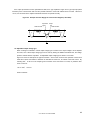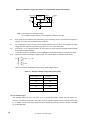
1
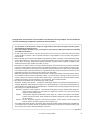
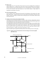
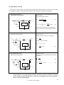
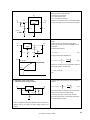
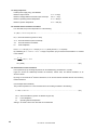
13. Tracking regulator circuit
+ VIN
+ VOUT
IN
C1
OUT
GND
0.1 µ F
0.1 µ F
C2
C3
0.1 µ F
C4
+
− VIN
0.1 µ F
GND
IN
OUT
R1
µPC741
−
R1
R2
R2
− VOUT
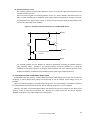
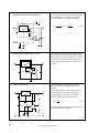
14. Positive and negative dual power supply circuit
(using positive voltage three-terminal regulators)
IN
This power supply has superior tracking characteristics
due to using an op amplifier and one positive and one
negative voltage three-terminal regulator.
The GND pin of each three-terminal regulator is driven
in common by the op amplifier output.
Favorable tracking characteristics are obtained by
making R1 = R2. Moreover, bias current errors also can
be canceled if the resistor R1//R2 is added between the
non-inverting pin of the op amplifier and GND.
+ VOUT
OUT
GND
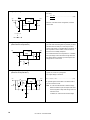
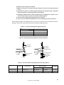
This is a positive and negative dual power supply that
uses two positive voltage three-terminal regulators.
D1 and D2 are low forward voltage diodes that are
absolutely necessary. They prevent output voltage
pulldown due to discrepancies in the startup timing of
each regulator.
D1
IN
GND
OUT
GND
D2
− VOUT
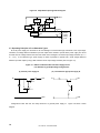
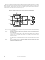
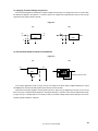
15. Wired OR
D1
VIN1
VOUT
When connecting the outputs of two or more threeterminal regulators, do it so that voltage from outside is
not added to the regulator output at D1 and D3.
D2 and D4 are connected to compensate for the lowering
of output by D1 and D3.
D2
D3
VIN2
D4
User’s Manual G12702EJ8V0UM00
21