1
Operation Manual
OM 127-1
Group: Controls
Date: May, 1998
MicroTech®
Chiller System Controller
For
Centrifugal (PEH & PFH),
Reciprocating (ALR & WHR),
Screw (PFS & ALS),
Global (AGZ, AGR, and AGS), and
J&E Hall Chillers
Chiller
System
Controller
MicroTech
a0165
© 1998 McQuay International
Contents
Contents................................................................................................................................................. 2
Figures ................................................................................................................................................... 3
Tables .................................................................................................................................................... 4
Introduction ........................................................................................................................................... 6
Software ID ........................................................................................................................................... 7
Software Compatibility...................................................................................................................... 7
Getting Started....................................................................................................................... 9
Chiller Definition................................................................................................................................... 9
Using the Keypad/Display..................................................................................................................... 9
Menu Structure ................................................................................................................................ 10
Display Format ................................................................................................................................ 10
Password Protection ........................................................................................................................ 11
Keypad/Display Modes ................................................................................................................... 11
Key Functions.................................................................................................................................. 11
Keypad/Display Exercises ............................................................................................................... 13
Keypad/Display Menu Reference ........................................................................................................ 14
Using the Tables .............................................................................................................................. 14
Browse Sequences ........................................................................................................................... 16
Status Menus ................................................................................................................................... 16
Control Menus ................................................................................................................................. 23
Alarm Menus ................................................................................................................................... 39
CSC and Chiller Controller Initial Setup ............................................................................................. 42
Setting Up the CSC.......................................................................................................................... 42
Setting Up Centrif-200 and HallScrew Chiller Controllers ............................................................. 46
Setting Up Centrif-100 Chiller Controllers...................................................................................... 47
Setting Up Recip-Standard, Screw, Recip-European, and AGU Chiller Controllers....................... 47
Operator’s Guide ................................................................................................................. 48
Determining Chiller System Status...................................................................................................... 48
CSC Operating State........................................................................................................................ 48
Current Chiller Stage ....................................................................................................................... 50
Chiller Load..................................................................................................................................... 51
Chiller Status (Generalized Operating State)................................................................................... 51
Water Temperatures ........................................................................................................................ 54
Chiller Run Time ............................................................................................................................. 55
Load Limiting Status ....................................................................................................................... 56
Chilled Water Distribution System Status ....................................................................................... 57
Cooling Tower Status ...................................................................................................................... 57
Auto/Manual Operation....................................................................................................................... 58
CSC Control Mode .......................................................................................................................... 58
Operator Override............................................................................................................................ 58
Network Override ............................................................................................................................ 59
Local Override................................................................................................................................. 60
Low Ambient Lockout..................................................................................................................... 61
Rapid Restart ................................................................................................................................... 61
Scheduling ........................................................................................................................................... 62
Setting Time and Date ..................................................................................................................... 63
Daily Scheduling ............................................................................................................................. 63
Holiday Scheduling ......................................................................................................................... 64
One-Event Scheduling ..................................................................................................................... 64
Optimal Start ................................................................................................................................... 65
Alarm Monitoring................................................................................................................................ 68
About Alarms .................................................................................................................................. 68
Displaying Alarms ........................................................................................................................... 70
Clearing Alarms............................................................................................................................... 71
2
OM127-1
Setting Up the Alarm Horn ..............................................................................................................71
Setting Up the Alarm Output ...........................................................................................................71
Description of Operation .................................................................................................... 73
Chiller Sequencing Control .................................................................................................................73
Sequence Order................................................................................................................................73
Normal Sequencing Logic ...............................................................................................................76
Special Sequencing Logic................................................................................................................80
Designating a Standby Chiller .........................................................................................................83
Load Limiting Control .........................................................................................................................84
Load Balancing................................................................................................................................84
Start-Up Unloading..........................................................................................................................84
Demand Limiting .............................................................................................................................85
Stage-Up Inhibiting..........................................................................................................................87
Soft Loading ....................................................................................................................................88
Chilled Water Temperature Control ....................................................................................................89
Setpoint Source at Chillers ..............................................................................................................89
Temperature Control........................................................................................................................91
Setpoint Reset ..................................................................................................................................95
Chilled Water Flow Control ..............................................................................................................100
Secondary Pump Logic: Single Pump............................................................................................102
Secondary Pump Logic: Lead/Standby Pump Set..........................................................................103
Secondary Pump Logic: Sequenced Pumps ...................................................................................105
Pump Speed Control ......................................................................................................................107
Loop Bypass Valve Control...........................................................................................................108
Cooling Tower Control......................................................................................................................109
Tower Staging Logic .....................................................................................................................110
Tower Bypass Valve Control.........................................................................................................115
Alarm Control....................................................................................................................................118
Comm Loss Alarms .......................................................................................................................118
Fault Alarms ..................................................................................................................................120
Problem Alarms .............................................................................................................................120
Warning Alarms.............................................................................................................................123
MicroTech PI Control Method.......................................................................................... 124
Change-and-Wait Algorithm..............................................................................................................124
About Change-and-Wait ................................................................................................................124
Description of Operation ...............................................................................................................124
Adjusting Change-and-Wait Parameters........................................................................................127
Project Ahead Algorithm...................................................................................................................128
About Project Ahead .....................................................................................................................128
Description of Operation ...............................................................................................................128
Adjusting Project Ahead Parameters .............................................................................................129
Figures
Figure 1. CSC Program Codification.....................................................................................................7
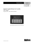
Figure 2. Keypad/Display Interface .......................................................................................................9
Figure 3. Keypad Accessible Menu Structure......................................................................................10
Figure 4. LCD Display Format ............................................................................................................10
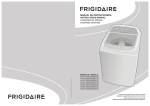
Figure 5. Keypad .................................................................................................................................12
Figure 6. Example of Screen and Corresponding Menu Table (Screen 2 of Menu 11 Shown) ...........15
Figure 7. Menu 8, Miscellaneous Inputs..............................................................................................22
Figure 8. Menu 17, Chilled Water Supply Temperature Reset ............................................................30
Figure 9. Chilled Water Temperature Sensor Locations......................................................................55
Figure 10. Condenser Water Temperature Sensor Locations ..............................................................55
Figure 11. Daily Schedule Fields.........................................................................................................63
Figure 12. One Event Schedule Fields.................................................................................................65
OM127-1
3
Figure 13. Optimal Start Time Line..................................................................................................... 66
Figure 14. Typical Primary-Only System ............................................................................................ 77
Figure 15. Typical Primary-Secondary System ................................................................................... 79
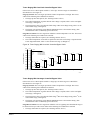
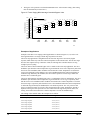
Figure 16. External Signal Demand Limiting Function ....................................................................... 86
Figure 17. Recip-Standard, Screw, Recip-European, and AGU Chiller Demand Limiting ................. 86
Figure 18. Chiller Leaving Evaporator Water Temperature Flow Chart ............................................. 90
Figure 19. CSC Leaving Evaporator Water Temperature Setpoint Flow Chart................................... 92
Figure 20. Typical System with Isolated Chillers ................................................................................ 93
Figure 21. Typical System with Nonisolated Chillers ......................................................................... 94
Figure 22. Return Water or Outdoor Air Reset (English).................................................................... 96
Figure 23. Return Water or Outdoor Air Reset (SI) ............................................................................ 97
Figure 24. External Reset (English)..................................................................................................... 98
Figure 25. External Reset (SI) ............................................................................................................. 98
Figure 26. Configuration. 1: Fixed-Speed Single Pump .................................................................... 100
Figure 27. Configuration. 2: Fixed-Speed Lead/Standby Pump Set .................................................. 101
Figure 28. Configuration. 3: Fixed-Speed Sequenced Pumps ........................................................... 101
Figure 29. Configuration. 4: Variable-Speed Single Pump ............................................................... 101
Figure 30. Configuration. 5: Variable-Speed Lead/Standby Pump Set ............................................. 102
Figure 31. Configuration. 6: Primary-Only System ........................................................................... 102
Figure 32.Typical Condenser Water Loop ........................................................................................ 110
Figure 33. Tower Staging Only ......................................................................................................... 112
Figure 34. Tower Staging With Low-Limit Controlled Bypass Valve .............................................. 113
Figure 35. Tower Staging With Intrastage Controlled Bypass Valve................................................ 114
Figure 36. Initial Tower Bypass Valve Position (English) ................................................................ 117
Figure 37. Initial Tower Bypass Valve Position (SI)......................................................................... 117
Figure 38. Change-and Wait Function: Direct Acting ....................................................................... 126
Figure 39. Change-and Wait Function: Reverse Acting .................................................................... 126
Figure 40. Project Ahead Example.................................................................................................... 129
Tables
Table 1 MicroTech Unit Controller Installation Literature ................................................................... 6
Table 2. MicroTech Unit Controller Operation Literature .................................................................... 6
Table 3. Program Code CSC1*01E Software Compatibility................................................................. 8
Table 4. CSC Chiller Software Terms ................................................................................................... 8
Table 5. Menu 1 System Status ........................................................................................................... 17
Table 6. Menu 2 Temperatures............................................................................................................ 17
Table 7. Menu 3 Chiller Status............................................................................................................ 18
Table 8. Menu 4, Chiller Operating Hours .......................................................................................... 20
Table 9. Menu 5, Load Limiting Status ............................................................................................... 21
Table 10. Menu 6, Cooling Tower Status............................................................................................ 21
Table 11. Menu 7, Flow To Load........................................................................................................ 22
Table 12. Menu 9, Miscellaneous Status ............................................................................................. 23
Table 13. Menu 10, System Control.................................................................................................... 25
Table 14. Menu 11, Chiller Sequencing .............................................................................................. 26
Table 15. Menu 12, Chiller Staging Factors........................................................................................ 26
Table 16. Menu 13, Chiller Sequence Order ....................................................................................... 28
Table 17. Menu 14, Load Limiting Setup............................................................................................ 29
Table 18. Menu 15, Start-Up Unloading ............................................................................................. 29
Table 19. Menu 16, Chilled Water Supply Temperature Control........................................................ 29
Table 20. Menu 18, Cooling Tower Stages ......................................................................................... 31
Table 21. Menu 19, Cooling Tower Output Sequence Order .............................................................. 31
Table 22. Menu 20, Cooling Tower Bypass Valve.............................................................................. 32
Table 23. Menu 21. Load Flow Control .............................................................................................. 33
Table 24. Menu 22. Secondary Pump Sequence Order ....................................................................... 33
Table 25. Menu 23. Time/Date............................................................................................................ 34
4
OM127-1
Table 26. Menu 24. Schedule ..............................................................................................................34
Table 27. Menu 25. Holiday Date .......................................................................................................35
Table 28. Menu 26. Optimal Start .......................................................................................................35
Table 29. Menu 27. Table of Optimal Start Time Increments (in Minutes) ........................................36
Table 30. Menu 28. Service.................................................................................................................36
Table 31. Menu 29. Chiller Setup........................................................................................................37
Table 32. Menu 30. Service Testing....................................................................................................38
Table 33. Menu 31. Current Alarms ....................................................................................................40
Table 34. Menu 32. CSC Alarm Buffer ...............................................................................................41
Table 35. Menu 33. Alarm Horn Setup ...............................................................................................41
Table 36. Menu 34. Alarm Output Setup.............................................................................................41
Table 37. Unit Setup Variables............................................................................................................46
Table 38. Off:Local Conditions at the Chiller .....................................................................................52
Table 39. Off:CSC Conditions at the Chiller .......................................................................................53
Table 40. Starting Conditions at the Chiller ........................................................................................53
Table 41. Running Conditions at the Chiller .......................................................................................53
Table 42. Stopping Conditions at the Chiller.......................................................................................54
Table 43. Default Optimal Start Time Increments (in Min.)................................................................66
Table 44. Default Alarm Indication Setup ...........................................................................................69
Table 45. CSC Alarms.........................................................................................................................69
Table 46. Example of Chiller Stage Table...........................................................................................73
Table 47. Soft Loading Variables: Centrif-200 and HallScrew ...........................................................88
Table 48. Soft Loading Variables: Centrif-100 ...................................................................................88
Table 49. Soft Loading Variables: Reciprocating/Screw.....................................................................88
Table 50. Setpoint Variables: Centrif-200 and HallScrew...................................................................89
Table 51. Setpoint Variables: Centrif-100 ...........................................................................................90
Table 52. Setpoint Variables: Reciprocating/Screw ............................................................................90
Table 53.Example of Pump Stage Table ...........................................................................................105
Table 54. Example of Tower Stage Table .........................................................................................111
Table 55. Actual Staging ...................................................................................................................111
Table 56. Change-and-Wait Controlled Variables and Setpoints for Direct Acting CSC Control
Strategies ...................................................................................................................................126
Table 57. Change-and-Wait Controlled Variables and Setpoints for Reverse Acting CSC Control
Strategies ...................................................................................................................................127
McQuay and MicroTech are registered trademarks of McQuay International.
Monitor and Open Protocol are trademarks of McQuay International.
©1998 McQuay International. All rights reserved throughout the world.
OM127-1
5
Introduction
This manual provides information about the MicroTech Chiller System Controller (CSC) for
McQuay centrifugal [PEH and PFH ( both available in series 100 and 200 controllers)],
reciprocating (ALR and WHR), screw (PFS and ALS), Global (AGZ, AGR, and AGS), and J&E Hall
Chillers. It specifically describes the CSC’s features, sequences of operation, and programmable
options. It also includes information on how to use the keypad/display to enter and display data.
For information on MicroTech components, field wiring options and requirements, network
commissioning procedures, and service procedures, refer to Bulletin No. IM 618, MicroTech Chiller
System Controller. For specific information about the MicroTech chiller controllers, refer to the
appropriate MicroTech unit controller installation or operation manual (see Table 1 and Table 2).
Table 1 MicroTech Unit Controller Installation Literature
Chiller Type
Bulletin Number
Series-100 Centrifugal
IM 403
Series-200 Centrifugal
IM 616
Reciprocating
IM 493
Screw
IM 549
Global (AGZ)
IM 686
Global (AGR)
IOM 690
Table 2. MicroTech Unit Controller Operation Literature
Chiller Type
Bulletin Number
Series-100 Centrifugal
OM 119
Series-200 Centrifugal
OM 125
Reciprocating
IM 493
Screw
IM 549
B Vintage Flooded Screw
OM 129
C Vintage Flooded Screw
OM 135
Global (AGU)
IOM 690
!
WARNING
Electric shock hazard.
Can cause personal injury or equipment damage.
This equipment must be properly grounded. Connections and service to the MicroTech control
panel must be performed only by personnel that are knowledgeable in the operation of the
equipment being controlled.
NOTICE
This equipment generates, uses and can radiate radio frequency energy and, if not installed
and used in accordance with this instruction manual, may cause interference to radio
communications. It has been tested and found to comply with the limits for a Class A digital
device, pursuant to part 15 of the FCC rules. These limits are designed to provide reasonable
protection against harmful interference when the equipment is operated in a commercial
environment. Operation of this equipment in a residential area is likely to cause harmful
interference in which case the user will be required to correct the interference at his or her
own expense. McQuay International disclaims any liability resulting from any
interference or for the correction thereof.
6
OM127-1
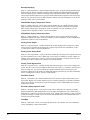
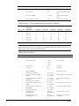
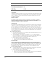
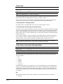
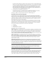
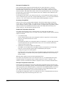
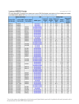
Software ID
MicroTech CSC software is factory installed and tested in each panel prior to shipment. The software
is identified by a program code (also referred to as the “Ident”), which is printed on a small label
affixed to the MCB. The program code is also encoded in the controller’s memory and is available for
display on menu 28 of the keypad/display or a PC equipped with MicroTech Monitor™ software.
Using menu 28 or the Monitor program is the most reliable way of determining the controller’s
program code.
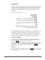
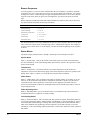
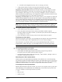
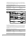
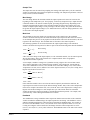
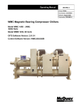
Figure 1. CSC Program Codification
CSC 1 E 01 F
Chiller System Controller
Program number
1 = Standard software
Units
E =English
S = SI
Version (nummeric)
Version revision (alphabetic)
a0239
If the CSC’s program code does not match the format shown above, it is likely that a special program
has been loaded into the controller and some of the information in this manual may not apply.
This edition documents revision F of the standard CSC software and all subsequent revisions of
version 01 until otherwise indicated. If your CSC software has a later revision code (for example,
CSC1E01H), some of the information in this manual may not apply to your software. However, since
revisions are usually very minor software changes, the discrepancies should be insignificant.
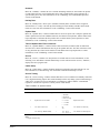
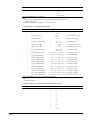
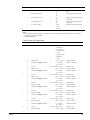
Software Compatibility
The current version is not compatible with some earlier versions of MicroTech centrifugal,
reciprocating, and screw chiller controller standard software. The current software compatibility is
summarized in Table 3. The wildcard character ( > ) can be any letter.
If you want to use a CSC with older chillers that have incompatible standard software, the chiller
software must be upgraded. (This applies to all Centrif-100 chillers.) If you have a version of chiller
software that has a later revision code than the compatible programs shown in Table 3, it is likely that
program CSC1 > 01 > is compatible with it; however, it may not be. To find out for sure, contact
McQuayService.
File Names
In all cases, the file names of the compatible programs shown in Table 3 are the same as the program
codes except that they also include a “COD” extension. For example, the file for program PC209A is
called “PC209A.COD.”
OM127-1
7
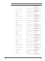
Table 3. Program Code CSC1*01E Software Compatibility
Chiller Controller
Compatible Programs
Incompatible Programs
Series-200 Centrifugal
CFG1*01C and later
CFG1*01B and earlier
CFG3*01C and later
CFG3*01B and earlier
Series-100 Centrifugal: Display Proc.
Series-100 Centrifugal: Control Proc.
Reciprocating
Screw
CFG5*01C and later
CFG5*01B and earlier
PDR09A and later
PDR08* and earlier
PDM09A and later
PDM08* and earlier
PC209A and later
PC208* and earlier
PC409A and later
PC408* and earlier
PC509A and later
PC508* and earlier
RCP1*01B and later
RCP1*01A
RCP2*01B and later
RCP2*01A
none
AWR-*12* and earlier
SC1*U01A
SC2*U18D and later
SC2*18C and earlier
SC3*E18C and later
SC3*E18B and earlier
SC4*E18C and later
SC4*E18B and earlier
J&E Hall
JEH**01K and later
Global
AG_UU01A and later
GZ_2E01A
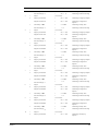
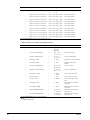
The menus within the CSC refer to the chiller software in generic terms. Table 4 lists each chiller
model and the generic term for its software.
Table 4. CSC Chiller Software Terms
8
Chiller Model
Software Term in CSC Menus
PFH
Centrif-100 (Series 100)
Centrif-200 (Series 200)
PEH
Centrif-100 (Series 100)
Centrif-200 (Series 200)
WHR
Recip-Standard
Recip-European
ALR
Recip-Standard
Recip-European
PFS
Screw
ALS
Screw
AGZ (Global Scroll)
AGU
AGR (Global
Reciprocating)
AGU
AGS (Global Screw)
AGU
J&E Hall
HallScrew
OM127-1
Getting Started
The MicroTech Chiller System Controller (CSC) is a self-contained device that is capable of
monitoring and controlling up to 12 McQuay centrifugal, reciprocating, screw, global, or J & E Hall
screw chillers via network communications. It can also monitor and control a variety of system
equipment such as cooling tower fans, bypass valves, and secondary pumps. You can display and
modify information in the CSC with either of the following methods:
• Using the keypad/display at the CSC
•
Using an optional PC equipped with the Monitor program
In addition to system data, the CSC’s keypad/display can show a summary of important data for each
chiller. To modify information in a chiller controller, you must use either the Monitor program or the
keypad/display at that chiller.
The “Getting Started” sections describe how to use the CSC’s keypad/display. For information on
using the optional Monitor program, see the Monitor User’s Manual. The last “Getting Started”
section describes how to set up the CSC and its associated chillers for normal operation.
Chiller Definition
As used throughout this manual, the word “chiller” means chiller in all cases except for dualcompressor centrifugals. For these machines, each compressor—along with its associated MicroTech
controller—is considered a “chiller.”
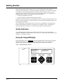
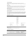
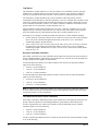
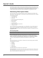
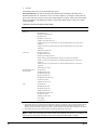
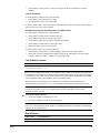
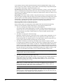
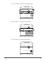
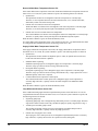
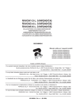
Using the Keypad/Display
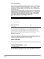
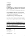
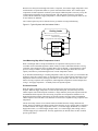
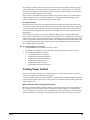
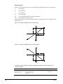
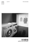
The Keypad/Display, shown in Figure 2, is provided with all MicroTech Chiller System Controllers.
With the keypad/display you can monitor operating conditions, alarms, control variables, and
schedules. After you enter the password, you can edit setpoints, variables, and schedules.
Figure 2. Keypad/Display Interface
Alarm
1.System Status
State= On:Schedule
Chiller Stage= 3
Chillers On= #1 #2
CATEGORY
Status
12:23
Jun-03-95
System Spt= 44.0°F
Average Load= 76%
#4
MENU - ITEM
Prev.
Item
Alarm
Next
Menu
Prev.
Menu
Control
Switch
Next
Item
ACTION
Incr.
Help
Clear
Decr.
Enter
a0070
OM127-1
9
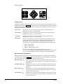
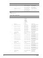
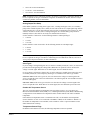
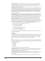
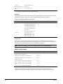
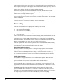
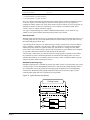
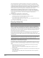
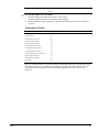
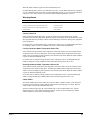
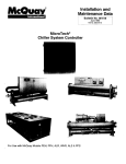
Menu Structure
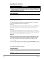
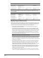
The keypad-accessible information in the MicroTech controller is organized in a menu structure to
provide quick access. As shown in Figure 3, this structure is divided into three levels: categories,
menus, and items. The category, which is the highest level in the structure, can be “Status,” “Control,”
or “Alarm.” The name of each category describes the basic purpose of the menus it contains.
Complete information on the contents of each menu is included in the following “Keypad/Display
Menu Reference” section.
Figure 3. Keypad Accessible Menu Structure
Category
Menu
Item
Status
Control
Alarm
Menu 1
Menu 2
Menu 9
Menu 10
Menu 11
Menu 30
Menu 31
Menu 32
Menu 35
Items on
Screen 1
Items on
Screen 1
Items on
Screen 1
Items on
Screen 1
Items on
Screen 1
Items on
Screen 1
Items on
Screen 1
Items on
Screen 1
Message
Board
Items on
Screen 2
Items on
Screen 2
Items on
Screen 2
Items on
Screen 2
Items on
Screen 3
Items on
Screen 3
Items on
Screen 3
Items on
Screen 3
Items on
Screen 4
Items on
Screen 4
Items on
Screen 5
Items on
Screen 5
a0072
Status Category
Menus in the Status category contain information about the current operation of the chiller system.
They also include important information about the current operating conditions in each chiller. The
fields in these menu items provide status information only and cannot be changed with the keypad.
Control Category
Menus in the Control category contain variables that define how the CSC operates. After the
password is entered, most fields in these menu items can be changed with the keypad.
Alarm Category
Menus in the Alarm category contain current and previous alarm information. They also include
variables that allow you to customize the setup of the CSC’s Alarm Horn and Alarm Output.
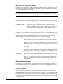
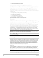
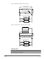
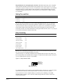
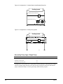
Display Format
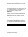
The information stored in the CSC’s menu structure can be viewed on the 4-line by 40-character LCD
display. As shown in Figure 4, the current menu is displayed on the top line and the current items are
displayed on the three lines below. An item line may contain one full-row item or two half-row items,
and each item contains one or more fields that convey varying information. These fields may or may
not be adjustable.
Figure 4. LCD Display Format
Screen
Menu line
Item line 1
Item line 2
Item line 3
Previous screen indicator
24.Schedule
14:34
Jun-03-95
Override= 0.00 Hrs
NMP Schedule= NA
One Event= Jun–12 18:30 for 2.25 Hrs
Sun 00:00–00:00
Mon 06:30–17:30
Field
Full-row item
Half-row item
Next screen indicator
a0071
10
OM127-1
In addition to the current menu, the menu line also shows the time, date, and a variety of other
messages that help you use the keypad.
The menu line and the three item lines are contained on a screen. A menu may contain one or more
screens. Each screen of a multi-screen menu (for example, menu 11) shows the same menu line and
different item lines. (The item lines do not scroll.) A down arrow in the display indicates that you can
display another screen of items by pressing the NEXT ITEM ( ) key. An up arrow in the display
indicates that you can display a previous screen of items by pressing the PREV ITEM key ( ).
Tabular Format
Some menus contain data that is displayed in a tabular format instead of the standard half- or full-row
item format shown in Figure 4. In the tabular format, the column headings are displayed on item line
1 and the data fields are displayed on item lines 2 and 3. If there is a stub, it is shown on the left side
of the screen. If there are multiple screens, the menu line and item line 1 (headings) are the same on
each screen. The CSC’s menu 27, “Optimal Minutes,” is an example of a tabular menu.
Password Protection
The MicroTech controller includes password protection to guard against the entry of inadvertent or
unauthorized changes. When you attempt to change the value of an adjustable variable with the
keypad, the controller prompts you to enter the password. If the correct password is entered, the
controller allows you to make changes as desired. Five minutes after the last keystroke is made, the
controller prevents further changes until the password is re-entered.
The keypad password for all controllers is the following keystroke sequence: ENTER, ENTER, ENTER,
ENTER. It is not adjustable. See “Key Functions” below for more information.
Keypad/Display Modes
The keypad/display has two modes of operation: Normal and Change Values. Depending on the
keypad/display mode, the function of each key changes. For more information, see “Key Functions.”
Normal Mode
In the Normal mode, you can use the keypad to move around the menu structure shown in Figure 3.
You can also clear alarms and get Help on using the keypad by pressing the CLEAR (Help) key. If you
want to edit a certain variable, first display it on the current screen and then go to the Change Values
mode by pressing INCR, DECR, or ENTER. The controller may prompt you for the password. The time
and date on the menu line are replaced by the message “<Change Values Mode>.”
Change Values Mode
In the Change Values mode, you can use the keypad to move around the screen and to change the
values of selected (flashing) fields. Any adjustable field on the current screen can be changed during
a change-values editing session: to edit a field on a different screen, you must first return to the
Normal mode and select the new screen. To return to the Normal mode, press the CLEAR key.
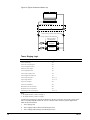
Key Functions
The MicroTech controller’s keypad consists of 12 pressure sensitive membrane switches, which are
divided into 3 groups: “Category,” “Menu-Item,” and “Action.” See Figure 5.
OM127-1
11
Figure 5. Keypad
CATEGORY
Status
MENU - ITEM
Prev.
Item
Alarm
Control
Switch
Help
Next
Menu
Prev.
Menu
ACTION
Next
Item
Incr.
Clear
Decr.
Enter
a0074
Category Group
Acting like bookmarks in the menu structure, the keys in the Category group provide quick access to
the desired menus. Refer to Figure 3. By using these keys, you can minimize scrolling between menus
with the keys in the Menu-Item group (see below). The keys in the Category group are active only
during the Normal mode.
STATUS Key:
Any time the STATUS key is pressed, the first menu in the Status category is
displayed. This is menu 1, “System Status.”
CONTROL Key:
Any time the CONTROL key is pressed, the first menu in the Control category is
displayed. This is menu 10, “System Control.”
ALARM Key:
Any time the ALARM key is pressed, the first menu in the Alarm category is
displayed. This is menu 31, “Current Alarms.”
SWITCH Key:
The SWITCH key allows you to quickly switch between menus that have closely
related content. For example, if you’re interested in chiller sequencing control,
you could go to menu 1, “System Status,” and then press the SWITCH key
successively to see the following menus, which contain chiller sequencing data:
•
Menu 1. System Status
•
Menu 3. Chiller Status
•
Menu 13. Chiller Sequence Order
The three menus in the above example are called a browse sequence
(1¤3¤13¤1). The following “Keypad/Display Menu Reference” section lists the
SWITCH essential destinations and browse sequences for all applicable menus.
Menu-Item Group: Normal Mode
During the Normal mode, the keys in the Menu-Item group allow you to choose the menu and item
you want to display. Refer to Figure 3. First use the two menu keys to select the menu you want, and
then, if necessary, use the two item keys to display the items you want.
12
PREV MENU Key ( ):
When the PREV MENU key is pressed, the display scrolls to the previous
menu in the structure. This action always occurs unless the current menu is
the first menu.
NEXT MENU Key ( ):
When the NEXT MENU key is pressed, the display scrolls to the next menu
in the structure. This action always occurs unless the current menu is the
last menu.
PREV ITEM Key ( ):
When the PREV ITEM key is pressed, the display scrolls to the previous
screen of items in the current menu. This action always occurs unless the
current screen is the first screen.
NEXT ITEM Key ( ):
When the NEXT ITEM key is pressed, the display scrolls to the next screen
of items in the current menu. This action always occurs unless the current
screen is the last screen.
OM127-1
Menu-Item Group: Change Values Mode
During the Change Values mode, the keys in the Menu-Item group become “cursor control” keys for
the current screen, allowing you to quickly get to the field(s) you want to edit. For more on editing,
see “Action Group: Change Values Mode.”
Note: In some instances during the Change Values mode, the flashing “cursor” field disappears
either upon entering the mode or after a keystroke. This is normal. An additional keystroke usually
makes the cursor field reappear.
Action Group: Normal Mode
During the Normal mode, the Action group keys allow you to (1) clear alarms, (2) get Help on using
the keypad/display, or (3) enter the Change Values mode. To enter the Change Values mode, press
the INCR, DECR, or ENTER key.
CLEAR Key (Help):
When the CLEAR key is pressed, the display shows Help on using the
keypad/display. This action always occurs except when menu 31, “Current
Alarms,” is in the display. In this instance, pressing CLEAR clears a current
CSC alarm. For more on clearing alarms, see the “Alarm Monitoring”
section of this manual.
Action Group: Change Values Mode
During the Change Values mode, the Action group keys allow you to edit values in the fields on the
current screen. When you enter the Change Values mode, the first adjustable field in the first item on
the current screen flashes, indicating that it can be edited with the INCR or DECR keys. To select
different fields on the screen, use the cursor control keys in the Menu-Item group.
INCR Key (+):
When the INCR key is pressed, the entry in the item’s selected (flashing) field
changes to the next higher value or next available selection. After pressing INCR,
you cannot select a new field for editing until you press the ENTER or CLEAR key.
DECR Key (–):
When the DECR key is pressed, the entry in the item’s selected (flashing) field
changes to the next lower value or previous available selection. After you press
DECR, you cannot select a new field for editing until you press the ENTER or
CLEAR key.
ENTER Key (=):
When the ENTER key is pressed after a value has been changed, the new entry is
locked in. A message appears on the menu line telling you that the change was
successful. To select another field for editing, use the cursor control keys in the
Menu-Item group. To end the edit, press CLEAR.
CLEAR Key:
The CLEAR key has two functions in the Change Values mode: (1) when CLEAR is
pressed after a value has been changed (but before the ENTER key is pressed), the
new entry is canceled and the previous entry is retained; (2) in any other case,
pressing CLEAR ends the editing session and returns the keypad/display to the
Normal mode.
Keypad/Display Exercises
Following are two exercises that guide you through some typical keypad operations. Often there is
more than one way to perform an operation. For example, you can use the Menu-Item keys with or
without the optional Category keys to quickly find the menu you want to display.
Changing a Setpoint
In this exercise, assume that the common chilled water supply temperature is 47.0°F (8.3°C) and
cooler water is required. The water temperature is too warm because not all chillers are on and both
the Minimum Chiller Setpoint and the System Setpoint are 44.0°F (6.6°C). (The system layout is such
that water from chillers that are off mixes with water from chillers that are on.) Using the following
procedure, you change the Minimum Chiller Setpoint to 41.0°F (4.9°C) and thus lower the common
supply temperature.
OM127-1
13
1.
2.
3.
4.
5.
6.
7.
8.
9.
Press CONTROL. The first menu of the Control category is displayed. This is menu 10, “System
Control.”
Press NEXT MENU ( ) six times. Menu 16, “Supply Tmp Cntl,” is displayed. The first screen of
this menu is also displayed.
Press NEXT ITEM ( ) once. The second screen is displayed. The “Min Chil Spt=” item is on the
right half of item line 1. This is the Minimum Chiller Setpoint. Assume that it is set to 44.0°F
(6.6°C).
Press INCR (+), DECR (–) or ENTER (=). The controller prompts you for the password.
Press ENTER four times. (This is the password.) The “Password Verified” message is displayed
and then the “<Change Values Mode>” message appears on the menu line.
Press NEXT MENU ( ), which is now a cursor control key, once. The “Min Chil Spt=” item’s only
field starts flashing.
Press DECR (–) until the setpoint is 41.0°F (4.9°C).
Press ENTER. The “Change Successful” message appears. This means that the new setpoint is
locked in. Now press CLEAR to end the edit and return to the keypad/display’s Normal mode.
Press SWITCH twice. The actual supply temperature (“Supply ChW=” item under menu 2,
“Temperatures”) is displayed. With the new setpoint entered, this temperature begins to drop.
Clearing a CSC Alarm
In this exercise, assume that a Fault alarm which requires a manual reset occurred in the system. If the
conditions that caused the alarm are gone, use the following procedure to clear the alarm.
1. Press ALARM. The Alarm Horn is silenced and the first menu of the Alarm category is displayed.
This is menu 31, “Current Alarms.” The “CSC=” item is also displayed. It probably shows
“None,” but assume that a Fault exists; for example, “No Sec ChW Flow.”
2. Press CLEAR. This clears the alarm and returns the CSC to normal operation. The “CSC=” item
automatically changes to “None.”
Keypad/Display Menu Reference
The following tables show every menu, item, and field in the menu structure of the CSC. These menus
and items can all be displayed with the keypad/display. (the Monitor program provides some
additional monitoring features and adjustable variables.)
Using the Tables
The menu tables tell you several things:
• The exact location of each item in the menu structure
•
The default value of each adjustable field
•
The range of possible values for each field
•
The variable name for each item
•
The SWITCH key destination for each menu
Figure 5 shows an example of a typical CSC screen and its corresponding menu table.
Location
Each menu table has a “Screen” (Scr.) column and a “Line” column. The Screen column tells you
which screen a particular item is on. The Line column tells you which item line a particular item is on.
For multi-screen menus, this information can be useful because it gives you an idea of the number of
times you need to press the NEXT ITEM key upon entering the menu.
14
OM127-1
Default Value
The tables for menus in the Control and Alarm categories show the default, factory set values of every
adjustable field. These are shown in the “Name” column in bold italic. For many variables, the default
values are typical values that may not need to be changed; for example, control loop parameters such
as deadbands and mod limits. Other variables must be set in accordance with the application, and thus
their default values have little meaning; for example, the First On Chiller variable shown in Figure 6.
Range
The range of possible values for every field is shown in the “Range” column. Since many items in the
Control and Alarm categories have more than one field, the tables for these menus also have a “Field
No.” column. If there is a number in the Field No. column, it indicates that the field is adjustable and
thus it can be selected with the cursor control keys during the Change Values mode. If there is a dash
(–) in the Field No. column, it indicates that the field is not adjustable. The range for each field is
shown in the adjacent Range column.
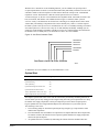
Using Figure 6 as an example, notice that all items on the screen have one adjustable field except “On
First=,” which has two. The “On First=” item’s first field can be set to “N/A,” “#1,” or “#2” through
“#12.” Its second field can be set to either “at Stage Two” or “Last.”
Note: The resolution of all adjustable temperature fields is 0.5°F (0.2–0.3°C).
Variable Name
Every item in the CSC’s menu structure represents a variable (adjustable or status only). The item
names that appear in the display are usually abbreviations of the variable names, which are listed in
the “Variable Name” column. Variable names are used in the text of this manual to describe the
operation of the CSC and its associated chillers.
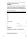
Figure 6. Example of Screen and Corresponding Menu Table (Screen 2 of Menu 11 Shown)
Screen 2
Menu line
Item line 1
Item line 2
Item line 3
11.Chil Sequencing
Standby= #1
On First= #2 & Off at Stage Two
On Last= #3 & Off First
Adjustable Field 1
15:20
Jun-03-95
Adjustable Field 2
a0073
Scr.
Line
Name (default values: bold italic)
Field
Range
Variable Name
2
1
Standby= NA
1
N/A, #1 – #12
Standby Chiller
2
On First= NA & Off Last
1
N/A, #1 – #12
First On Chiller
2
at Stage Two
Last
3
On Last= NA & Off First
1
N/A, #1 – #12
Last On Chiller
SWITCH Key Destination: Menu 3. Chiller Status
SWITCH Key Destination
At the bottom of each menu table, the SWITCH key destination for that menu (if any) is shown. The
SWITCH key destination is the menu the CSC displays after the SWITCH key is pressed. For example, if
menu 11 is in the display, pressing SWITCH displays menu 3.
OM127-1
15
Browse Sequences
A browse sequence is a series of closely related menus that you can display cyclically by repeatedly
pressing the SWITCH key. They allow you to focus on a specific chiller system function—for example,
cooling tower control—without having to navigate through unrelated menus. You can enter a browse
sequence at any menu, and if you press SWITCH enough times, you return to the menu you started
from.
Browse sequences include only menus that contain information you may need on a day-to-day basis;
they do not include menus that contain setup information.
Topic
Browse Sequence Menus
Chiller Sequencing
1¤3¤13¤1
System/Scheduling
10¤24¤10
Chilled Water Temperatures
2¤16¤17¤2
Cooling Tower
6¤18¤19¤20¤6
Load Limiting
5¤14¤15¤5
Chilled Water Flow
7¤21¤22¤7
Not all menus that have SWITCH key destinations are part of a browse sequence. However, if you press
SWITCH from one of these menus, it usually brings you to a related browse sequence. For example, if
you press SWITCH while menu 11 is in the display, you enter the Chiller Sequencing browse sequence
at menu 3.
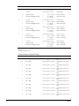
Status Menus
The Status category includes menus 1 through 9. Following are brief descriptions of them.
System Status
Menu 1, “System Status,” tells you the current overall status of the CSC and its associated chillers.
For more information, see the “Determining Chiller System Status” section in the “Operator’s Guide”
portion of this manual.
Temperatures
Menu 2, “Temperatures,” provides the current system water temperatures and the outdoor air
temperature. Except for the chilled water supply sensor, these temperature sensors are optional. If the
display shows “Open” or “Short,” it is likely that the sensor has not been installed.
Chiller Status
Menu 3, “Chiller Status,” tells you whether each chiller is currently starting, on, stopping, or off. If a
chiller is off, the chiller status tells whether it is disabled at the chiller or by the CSC. The load on
each chiller and the water temperatures at each chiller are also displayed. The chiller load is in
percent of rated load amps (% RLA) for centrifugal and percent of available stages that are active for
reciprocating and screw.
Chiller Operating Hours
Menu 4, “Operating Hours,” gives you run-time history for each chiller in the system. Run time is
accumulated whenever a compressor is actually running.
Load Limiting Status
Menu 5, “Load Limit Status,” tells you which of the three percent-of-capacity load limiting functions
are currently affecting the chillers: demand limiting, load balancing, or start-up unloading. A value of
100% means that no load limiting is occurring. The current capacity limit on each individual chiller,
which is the minimum value produced by the three functions, is also shown on menu 5. For more
information, see the “Determining Chiller System Status” section in the “Operator’s Guide” portion of
this manual.
16
OM127-1
Cooling Tower Status
Menu 6, “Tower Status,” tells you the current status of the cooling tower system. For more
information, see the “Determining Chiller System Status” section in the “Operator’s Guide” portion of
this manual.
Flow To Load
Menu 7, “Flow To Load,” tells you the current status of the chilled water distribution system, which
may include secondary pumps or a differential pressure bypass valve. For more information, see the
“Determining Chiller System Status” section in the “Operator’s Guide” portion of this manual.
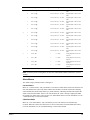
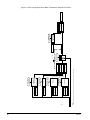
Miscellaneous Inputs
Menu 8, “Misc Inputs,” tells you the flow rate in the decoupler line and the states of the external
start/stop, chilled water reset override, and cooling tower alarm inputs. The conditioned (0–5 Vdc)
values of the external demand limiting and external chilled water reset signals are also displayed.
Miscellaneous Status
Menu 9, “Misc Status,” tells you the current value of the Stage-Up Inhibit Level variable. This signal
can be sent to the CSC by a MicroTech Network Master Panel that has a demand meter connected to
it or by a building automation system via Open Protocol™. The signal and its corresponding setpoint
(menu 11) can be used to prevent further chiller system loading when a certain electrical demand
target is reached.
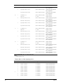
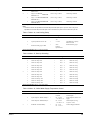
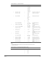
Table 5. Menu 1 System Status
Scr
Line
Name (typical values shown italic)
Range
Variable Name
1
1
State= On:Schedule
• Off:Unocc
CSC Operating State
• Off:Manual
• Off:Ambient
• Off:Network
• Off:Alarm
• Recirculate
• On:Schedule
• On:Input
• On:Manual
• On:Network
• Free Clg
2
3
System Spt= 44.0°F (6.6°C)
32.0 – 60.0°F
0.0 – 20.0°C {
System Setpoint (chilled water
supply)
Chiller Stage= 2
0 – 12
Current Chiller Stage
Average Load= 67%
0 – 125%
Average Chiller Load
(operational chillers)
Chillers On= #1 #2 __ __ __ __ __ __
__ __ __ __
#1 - #12 |
Chiller Status Bitset
SWITCH Key Destination: Menu 3. Chiller Status
Notes:
1. Program CSC1S01 > only.
2. If a chiller is either starting or running, that chiller’s number appears in the item line.
Table 6. Menu 2 Temperatures
OM127-1
Scr
Line
Name (typical values shown italic)
Range
Variable Name
1
1
Supply ChW= 44.2°F (6.7°C)
–45.0 – 255.0°F
–40.0 – 125.0°C{
Chilled Water Supply
Temperature (common)
Return ChW= 54.6°F (12.6°C)
–45.0 – 255.0°F, N/A
–40.0 – 125.0°C{, N/A
Chilled Water Return
Temperature
17
Scr
Line
Name (typical values shown italic)
Range
Variable Name
2
Ent CondW= 79.5°F (26.4°C)
–45.0 – 255.0°F, N/A
–40.0 – 125.0°C{, N/A
Common Entering Condenser
Water Temperature
Lvg CondW= 92.1°F (33.4°C)
–45.0 – 255.0°F, N/A
–40.0 – 125.0°C{, N/A
Common Leaving Condenser
Water Temperature
Decoupler= 45.1°F (7.3°C)
–45.0 – 255.0°F, N/A
–40.0 – 125.0°C{, N/A
Decoupler Temperature
Outdoor Air= 90.0°F (32.2°C)
–45.0 – 255.0°F, N/A
–40.0 – 125.0°C{, N/A
Outdoor Air Temperature
3
SWITCH Key Destination: Menu 16. Chilled Water Supply Temperature Control
Notes:
1. Program CSC1S01 > only.
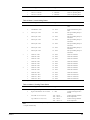
Table 7. Menu 3 Chiller Status
Scr
Line
Name (typical values shown italic)
Range
Variable Name
1
1
#1 Status= Running
• Off:Local
Chiller #1 Status
• Off:CSC
• Starting
• Running
• Stopping
• Comm Loss
• N/A
2
3
2
1
2
3
3
1
2
3
4
18
1
Load= 54%
0 – 125%
Chiller #1 Load
Ent Evap= 53.6°F (12.0°C)
–45.0 – 255.0°F
–40.0 – 125.0°C {
Chiller #1 Entering Evaporator
Water Temperature
Ent Cond= 75.7°F (24.3°C)
–45.0 – 255.0°F
–40.0 – 125.0°C {
Chiller #1 Entering Condenser
Water Temperature
Lvg Evap= 44.2°F (6.8°C)
–45.0 – 255.0°F
–40.0 – 125.0°C {
Chiller #1 Leaving Evaporator
Water Temperature
Lvg Cond= 85.6°F (29.8°C)
–45.0 – 255.0°F
–40.0 – 125.0°C {
Chiller #1 Leaving Condenser
Water Temperature
#2 Status= Running
(same as Chiller #1 Status)
Chiller #2 Status
Load= 57%
0 – 125%
Chiller #2 Load
Ent Evap= 53.8°F (12.1°C)
(same as Chiller #1 temps.)
Chiller #2 Entering Evaporator
Water Temperature
Ent Cond= 75.9°F (24.4°C)
(same as Chiller #1 temps.)
Chiller #2 Entering Condenser
Water Temperature
Lvg Evap= 44.3°F (6.8°C)
(same as Chiller #1 temps.)
Chiller #2 Leaving Evaporator
Water Temperature
Lvg Cond= 85.8°F (29.9°C)
(same as Chiller #1 temps.)
Chiller #2 Leaving Condenser
Water Temperature
#3 Status= Running
(same as Chiller #1 Status)
Chiller #3 Status
Load= 55%
0 – 125%
Chiller #3 Load
Ent Evap= 53.9°F (12.2°C)
(same as Chiller #1 temps.)
Chiller #3 Entering Evaporator
Water Temperature
Ent Cond= 75.5°F (24.2°C)
(same as Chiller #1 temps.)
Chiller #3 Entering Condenser
Water Temperature
Lvg Evap= 44.6°F (7.0°C)
(same as Chiller #1 temps.)
Chiller #3 Leaving Evaporator
Water Temperature
Lvg Cond= 85.7°F (29.8°C)
(same as Chiller #1 temps.)
Chiller #3 Leaving Condenser
Water Temperature
#4 Status= Off:CSC
(same as Chiller #1 Status)
Chiller #4 Status
Load= 0%
0 – 125%
Chiller #4 Load
OM127-1
Scr
Line
Name (typical values shown italic)
Range
Variable Name
2
Ent Evap= 56.3°F (13.5°C)
(same as Chiller #1 temps.)
Chiller #4 Entering Evaporator
Water Temperature
Ent Cond= 80.7°F (27.1°C)
(same as Chiller #1 temps.)
Chiller #4 Entering Condenser
Water Temperature
Lvg Evap= 56.2°F (13.4°C)
(same as Chiller #1 temps.)
Chiller #4 Leaving Evaporator
Water Temperature
Lvg Cond= 81.0°F (27.2°C)
(same as Chiller #1 temps.)
Chiller #4 Leaving Condenser
Water Temperature
#5 Status= N/A
(same as Chiller #1 Status)
Chiller #5 Status
Load= 0%
0 – 125%
Chiller #5 Load
Ent Evap= 20.0°F (–6.7°C)
(same as Chiller #1 temps.)
Chiller #5 Entering Evaporator
Water Temperature
Ent Cond= 55.0°F (12.8°C)
(same as Chiller #1 temps.)
Chiller #5 Entering Condenser
Water Temperature
Lvg Evap= 20.0°F (–6.7°C)
(same as Chiller #1 temps.)
Chiller #5 Leaving Evaporator
Water Temperature
Lvg Cond= 55.0°F (12.8°C)
(same as Chiller #1 temps.)
Chiller #5 Leaving Condenser
Water Temperature
#6 Status= N/A
(same as Chiller #1 Status)
Chiller #6 Status
Load= 0%
0 – 125%
Chiller #6 Load
Ent Evap= 20.0°F (–6.7°C)
(same as Chiller #1 temps.)
Chiller #6 Entering Evaporator
Water Temperature
Ent Cond= 55.0°F (12.8°C)
(same as Chiller #1 temps.)
Chiller #6 Entering Condenser
Water Temperature
Lvg Evap= 20.0°F (–6.7°C)
(same as Chiller #1 temps.)
Chiller #6 Leaving Evaporator
Water Temperature
Lvg Cond= 55.0°F (12.8°C)
(same as Chiller #1 temps.)
Chiller #6 Leaving Condenser
Water Temperature
3
5
1
2
3
6
1
2
3
7
1
2
3
8
1
2
3
9
1
2
OM127-1
#7 Status= N/A
(same as Chiller #1 Status)
Chiller #7 Status
Load= 0%
0 – 125%
Chiller #7 Load
Ent Evap= 20.0°F (–6.7°C)
(same as Chiller #1 temps.)
Chiller #7 Entering Evaporator
Water Temperature
Ent Cond= 55.0°F (12.8°C)
(same as Chiller #1 temps.)
Chiller #7 Entering Condenser
Water Temperature
Lvg Evap= 20.0°F (–6.7°C)
(same as Chiller #1 temps.)
Chiller #7 Leaving Evaporator
Water Temperature
Lvg Cond= 55.0°F (12.8°C)
(same as Chiller #1 temps.)
Chiller #7 Leaving Condenser
Water Temperature
#8 Status= N/A
(same as Chiller #1 Status)
Chiller #8 Status
Load= 0%
0 – 125%
Chiller #8 Load
Ent Evap= 20.0°F (–6.7°C)
(same as Chiller #1 temps.)
Chiller #8 Entering Evaporator
Water Temperature
Ent Cond= 55.0°F (12.8°C)
(same as Chiller #1 temps.)
Chiller #8 Entering Condenser
Water Temperature
Lvg Evap= 20.0°F (–6.7°C)
(same as Chiller #1 temps.)
Chiller #8 Leaving Evaporator
Water Temperature
Lvg Cond= 55.0°F (12.8°C)
(same as Chiller #1 temps.)
Chiller #8 Leaving Condenser
Water Temperature
#9 Status= N/A
(same as Chiller #1 Status)
Chiller #9 Status
Load= 0%
0 – 125%
Chiller #9 Load
Ent Evap= 20.0°F (–6.7°C)
(same as Chiller #1 temps.)
Chiller #9 Entering Evaporator
Water Temperature
19
Scr
Line
3
10
1
2
3
11
1
2
3
12
1
2
3
Name (typical values shown italic)
Range
Variable Name
Ent Cond= 55.0°F (12.8°C)
(same as Chiller #1 temps.)
Chiller #9 Entering Condenser
Water Temperature
Lvg Evap= 20.0°F (–6.7°C)
(same as Chiller #1 temps.)
Chiller #9 Leaving Evaporator
Water Temperature
Lvg Cond= 55.0°F (12.8°C)
(same as Chiller #1 temps.)
Chiller #9 Leaving Condenser
Water Temperature
#10 Status= N/A
(same as Chiller #1 Status)
Chiller #10 Status
Load= 0%
0 – 125%
Chiller #10 Load
Ent Evap= 20.0°F (–6.7°C)
(same as Chiller #1 temps.)
Chiller #10 Entering Evaporator
Water Temperature
Ent Cond= 55.0°F (12.8°C)
(same as Chiller #1 temps.)
Chiller #10 Entering Condenser
Water Temperature
Lvg Evap= 20.0°F (–6.7°C)
(same as Chiller #1 temps.)
Chiller #10 Leaving Evaporator
Water Temperature
Lvg Cond= 55.0°F (12.8°C)
(same as Chiller #1 temps.)
Chiller #10 Leaving Condenser
Water Temperature
#11 Status= N/A
(same as Chiller #1 Status)
Chiller #11 Status
Load= 0%
0 – 125%
Chiller #11 Load
Ent Evap= 20.0°F (–6.7°C)
(same as Chiller #1 temps.)
Chiller #11 Entering Evaporator
Water Temperature
Ent Cond= 55.0°F (12.8°C)
(same as Chiller #1 temps.)
Chiller #11 Entering Condenser
Water Temperature
Lvg Evap= 20.0°F (–6.7°C)
(same as Chiller #1 temps.)
Chiller #11 Leaving Evaporator
Water Temperature
Lvg Cond= 55.0°F (12.8°C)
(same as Chiller #1 temps.)
Chiller #11 Leaving Condenser
Water Temperature
#12 Status= N/A
(same as Chiller #1 Status)
Chiller #12 Status
Load= 0%
0 – 125%
Chiller #12 Load
Ent Evap= 20.0°F (–6.7°C)
(same as Chiller #1 temps.)
Chiller #12 Entering Evaporator
Water Temperature
Ent Cond= 55.0°F (12.8°C)
(same as Chiller #1 temps.)
Chiller #12 Entering Condenser
Water Temperature
Lvg Evap= 20.0°F (–6.7°C)
(same as Chiller #1 temps.)
Chiller #12 Leaving Evaporator
Water Temperature
Lvg Cond= 55.0°F (12.8°C)
(same as Chiller #1 temps.)
Chiller #12 Leaving Condenser
Water Temperature
SWITCH Key Destination: Menu 13. Chiller Sequence Order
Notes:
1. Program CSC1S01 > only.
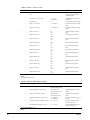
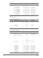
Table 8. Menu 4, Chiller Operating Hours
Scr
Line
Name (typical values shown italic)
Range
Variable Name
1
1
Chil #1= 12345 Hrs
0 – 49999 Hrs
Chiller #1 Operating Hours
2
Chil #2= 12345 Hrs
0 – 49999 Hrs
Chiller #2 Operating Hours
3
Chil #3= 12345 Hrs
0 – 49999 Hrs
Chiller #3 Operating Hours
1
Chil #4= 12345 Hrs
0 – 49999 Hrs
Chiller #4 Operating Hours
2
Chil #5= 12345 Hrs
0 – 49999 Hrs
Chiller #5 Operating Hours
3
Chil #6= 12345 Hrs
0 – 49999 Hrs
Chiller #6 Operating Hours
1
Chil #7= 12345 Hrs
0 – 49999 Hrs
Chiller #7 Operating Hours
2
Chil #8= 12345 Hrs
0 – 49999 Hrs
Chiller #8 Operating Hours
2
Chil #9= 12345 Hrs
0 – 49999 Hrs
Chiller #9 Operating Hours
2
20
OM127-1
Scr
Line
Name (typical values shown italic)
Range
Variable Name
3
Chil #10= 12345 Hrs
0 – 49999 Hrs
Chiller #10 Operating Hours
1
Chil #11= 12345 Hrs
0 – 49999 Hrs
Chiller #11 Operating Hours
2
Chil #12= 12345 Hrs
0 – 49999 Hrs
Chiller #12 Operating Hours
SWITCH Key Destination: Menu 13. Chiller Sequence Order
Table 9. Menu 5, Load Limiting Status
Scr
Line
Name (typical values shown italic)
Range
Variable Name
1
1
Demand Limit= 100%
40 – 100%
System Demand Limiting Load
Limit
2
Load Balance= 100%
30 – 125%
System Load Balancing Load
Limit
1
Start Grp #1= 100%
30 – 100%
Start-Up Unloading Group #1
Load Limit
2
Start Grp #2= 100%
30 – 100%
Start-Up Unloading Group #2
Load Limit
3
Start Grp #3= 100%
30 – 100%
Start-Up Unloading Group #3
Load Limit
1
Start Grp #4= 100%
30 – 100%
Start-Up Unloading Group #4
Load Limit
2
Start Grp #5= 100%
30 – 100%
Start-Up Unloading Group #5
Load Limit
3
Start Grp #6= 100%
30 – 100%
Start-Up Unloading Group #6
Load Limit
1
Chiller #1= 100%
30 – 100%
Chiller #1 Load Limit
2
Chiller #2= 100%
30 – 100%
Chiller #2 Load Limit
3
Chiller #3= 100%
30 – 100%
Chiller #3 Load Limit
1
Chiller #4= 100%
30 – 100%
Chiller #4 Load Limit
2
Chiller #5= 100%
30 – 100%
Chiller #5 Load Limit
3
Chiller #6= 100%
30 – 100%
Chiller #6 Load Limit
1
Chiller #7= 100%
30 – 100%
Chiller #7 Load Limit
2
Chiller #8= 100%
30 – 100%
Chiller #8 Load Limit
3
Chiller #9= 100%
30 – 100%
Chiller #9 Load Limit
1
Chiller #10= 100%
30 – 100%
Chiller #10 Load Limit
2
Chiller #11= 100%
30 – 100%
Chiller #11 Load Limit
3
Chiller #12= 100%
30 – 100%
Chiller #12 Load Limit
Name (typical values shown italic)
Range
Variable Name
2
3
4
SWITCH Key Destination: Menu 14. Load Limiting Setup
Table 10. Menu 6, Cooling Tower Status
Scr
1
Line
1
Cooling Tower Stage= 2
0 – 12
Current Cooling Tower Stage
2
Bypass Valve Position= 95% To Tower
0 – 100%
Cooling Tower Bypass Valve
Position
3
Ent CndW T= 79.5°F (26.4°C)
–45.0 – 255.0°F
–40.0 – 125.0°C {
Common Entering Condenser
Water Temperature
Lvg CndW T= 92.1°F (33.4°C)
–45.0 – 255.0°F
–40.0 – 125.0°C {
Common Leaving Condenser
Water Temperature
SWITCH Key Destination: Menu 18. Cooling Tower Stages
Notes:
1. Program CSC1S01 > only.
OM127-1
21
Table 11. Menu 7, Flow To Load
Scr
Line
Name (typical values shown italic)
Range
Variable Name
1
1
Pressure Bypass Valve or VFD Pump=
30%
0 – 100%
Differential Pressure Bypass
Valve Position or Secondary
VFD Pump Speed
2
Press Diff= 19 psi (131 kPa)
0 – 99 psi
0 – 650 kPa {
Chilled Water Loop Pressure
Difference
Pump Stage= 0
0–9
Current Sequenced Pump Stage
Pump #1= 12345 Hrs
0 – 49999 Hrs
Secondary Pump #1 Operating
Hours
Pump #2= 12345 Hrs
0 – 49999 Hrs
Secondary Pump #2 Operating
Hours
Pump #1 Out= On
On
Off
Secondary Pump #1 Output
State
Pump #1 Status= On
On
Off
Secondary Pump #1 Status
Pump #2 Out= Off
On
Off
Secondary Pump #2 Output
State
Pump #2 Status= Off
On
Off
Secondary Pump #2 Status
Pump #3 Out= Off
On
Off
Secondary Pump #3 Output
State
Pump #3 Status= Off
On
Off
Secondary Pump #3 Status
Pump #4 Out= Off
On
Off
Secondary Pump #4 Output
State
Pump #4 Status= Off
On
Off
Secondary Pump #4 Status
Pump #5 Out= Off
On
Off
Secondary Pump #5 Output
State
Pump #5 Status= Off
On
Off
Secondary Pump #5 Status
Pump #6 Out= Off
On
Off
Secondary Pump #6 Output
State
Pump #6 Status= Off
On
Off
Secondary Pump #6 Status
3
2
1
2
3
3
1
2
3
SWITCH Key Destination: Menu 21. Load Flow Control
Notes:
1. Program CSC1S01 > only.
Figure 7. Menu 8, Miscellaneous Inputs
Scr
Line
Name (typical values shown italic)
Range
Variable Name
1
1
External Start/Stop= Auto
Auto (input open)
Occupied (input closed)
External Start/Stop Status
2
Supply ChW Reset Override= Auto
Auto (input open)
Override (input closed)
Chilled Water Reset Override
Status
3
Cooling Tower Alarm= Normal
Fail (input open)
Normal (input closed)
Cooling Tower Alarm Input
Status
1
Decoupler Flow Rate= 500 gpm (31.5
L/s)
0 – 5000 gpm
0 – 300.0 L/s {
Decoupler Flow Rate (supply to
return)
2
External Demand Limit Signal= 0.0 Vdc
0.0 – 5.0 Vdc
External Demand Limiting
Signal (conditioned)
3
External ChW Reset Signal= 0.0 Vdc
0.0 – 5.0 Vdc
External Chilled Water Reset
Signal (conditioned)
2
SWITCH Key Destination: None
Notes:
22
OM127-1
1. Program CSC1S01 > only.
Table 12. Menu 9, Miscellaneous Status
Scr
Line
Name (typical values shown italic)
Range
Variable Name
1
1
Stage-Up Inhibit Level= 2
None
1–7
Stage-Up Inhibit Level (via
network comm.)
SWITCH Key Destination: Menu 11. Chiller Sequencing
Control Menus
The Control category includes menus 10 through 30. Following are brief descriptions of them.
System Control
Menu 10, “System Control,” contains the CSC Control Mode variable, which allows you to set up the
CSC for automatic or manual operation. It also contains the low ambient lockout variables that are
used to prevent chiller system operation when the outdoor air temperature is below a set temperature.
For more information, see the “Auto/Manual Operation” section in the “Operator’s Guide” portion of
this manual.
Chiller Sequencing
Menu 11, “Chil Sequencing,” can be used to designate whether the chiller sequence order is set
manually or automatically and whether certain chillers are designated as standby, first on, or last on. It
can also be used to set up the CSC’s chiller sequencing control logic. For more information, see the
“Chiller Sequencing Control” section of this manual.
Chiller Staging Factors
Menu 12, “Chil Stg Factors,” contains the variables that cause the active chiller stage number to
increase or decrease as the cooling load varies. Individual variables are provided for each chiller
stage. Chiller staging is based on the average load of all operational chillers, an adjustable time delay,
and in some applications, flow rate through the decoupler (bypass) line.
In addition to the chiller staging variables, a limit on the number of cooling tower stages can be
specified. For more information, see the “Chiller Sequencing Control” section of this manual.
Chiller Sequence Order
Menu 13, “Chiller Order,” shows the order in which the CSC sequences chillers as the cooling load
varies. When the CSC is set up to change the sequence order automatically, the variables in menu 13
are status only (non-adjustable). When the CSC is set up to allow manual sequence order changes, the
variables in menu 13 are used to set a fixed sequence order.
In either case, the sequence order is organized according to chiller stages rather than individual
chillers. A chiller stage is a defined set of chillers; for example, stage 1 might consist of Chiller #2,
and stage 2 might consist of Chiller #1 and Chiller #2. (In this instance, Chiller #2 would be “lead”
and Chiller #1 would be “lag.”) This approach provides more sequencing flexibility because chillers
can be either started or stopped in sets of one or more as the cooling load either increases or
decreases. For more information, see the “Chiller Sequencing Control” section of this manual.
Load Limiting Setup
Menu 14, “Load Limiting,” contains variables that allow you to set up the two system-wide, percentof-capacity load limiting functions: load balancing and demand limiting. Both are optional.
Load balancing causes all centrifugal chillers to operate at about the same capacity (% RLA). It is
typically used when there are dual-compressor chillers or chillers piped in series.
Demand limiting prevents chillers from operating above a specified capacity (% RLA for centrifugal;
stages for reciprocating and screw). The demand-limiting signal can be either an external input
(4-20 mA, 1–5 Vdc, 2–10 Vdc) or a network input received via Open Protocol. For more information,
see the “Load Limiting Control” of this manual.
OM127-1
23
Start-Up Unloading
Menu 15, “Start-Up Unload,” contains variables that allow you to set up the start-up-unloading load
limiting function. Start-up unloading is different from load balancing and demand limiting in that it
works on separate groups of chillers (centrifugal only) rather than all chillers. Start-up unloading
causes all operational compressors in a group to unload when another compressor in the same group
starts up. It is typically used only for dual-compressor chillers. For more information, see the “Load
Limiting Control” section of this manual.
Chilled Water Supply Temperature Control
Menu 16, “Supply Tmp Cntl,” can be used to specify whether the CSC controls common (system
supply) chilled water temperature or controls unit (leaving evaporator) chilled water temperature.
Either control method can be used with any of the reset options. For more information, see the
“Chilled Water Temperature Control” section of this manual.
Chilled Water Supply Temperature Reset
Menu 17, “Supply Tmp Reset,” contains variables that are used to reset the chilled water supply
temperature setpoint. Four types of reset are available. For more information, see the “Chilled Water
Temperature Control” section of this manual.
Cooling Tower Stages
Menu 18, “Clg Tower Stages,” contains variables that control staging for the cooling tower system.
Twelve stages are possible, and each stage has a separate setpoint. For more information, see the
“Cooling Tower Control” section of this manual.
Cooling Tower Output Order
Menu 19, “Twr Output Order,” can be set the order in which the CSC stages tower outputs as the heat
rejection requirement varies. Like a chiller stage, a tower stage is a defined set of tower outputs; for
example, stage 1 might consist of Fan #1, stage 2 of Fan #2, and stage 3 of Fan #1 and #2. For more
information, see the “Cooling Tower Control” section of this manual.
Cooling Tower Bypass Valve
Menu 20, “Clg Tower Valve,” contains variables that control the bypass valve for the cooling tower
system. The valve can be set up to modulate either before tower stage 1 is activated or between tower
stages. In either case, you can set an initial valve position function, which sets the bypass valve
position as appropriate for the outdoor air temperature during system start-up. For more information,
see the “Cooling Tower Control” section in of this manual.
Load Flow Control
Menu 21, “Load Flow Cntl,” contains variables that can be used to set up the chilled water system
flow control. Bypass valve control and three types of secondary pump logic are possible. Secondary
pumps can be fixed or variable speed. For more information, see the “Chilled Water Flow Control”
section of this manual.
Secondary Pump Sequence Order
Menu 22, “Sec Pump Order,” can be used to set the order in which the CSC sequences secondary
pumps to maintain the differential pressure across the supply and return lines. Like a chiller stage, a
pump stage is a defined set of pumps; for example, stage 1 might consist of Pump #1, stage 2 of Pump
#1 and #2, and stage 3 of Pump #1, #2, and #3. For more information, see the “Chilled Water Flow
Control” section of this manual.
Time/Date
Menu 23, “Time/Date,” allows you to adjust the current time, day, and date. For more information,
see the “Scheduling” section of this manual.
24
OM127-1
Schedule
Menu 24, “Schedule,” contains the CSC’s internal scheduling variables. It also includes an operator
override timer and a one-event schedule that can be used to enable chiller system operation for a
specified time period. For more information, see the “Scheduling” and “Auto/Manual Operation”
sections of this manual.
Holiday Date
Menu 25, “Holiday Date,” allows you to schedule 12 holiday dates. Each date can be assigned a
duration from 1 to 31 days. On each day of the holiday period, the holiday schedule entered under
menu 24 is used. For more information, see the “Scheduling” section of this manual.
Optimal Start
Menu 26, “Optimal Start,” contains variables that are used to set up the CSC’s adaptive optimal start
feature. Optimal start uses the scheduled start time, the outdoor air temperature, and the chilled water
loop temperature to determine the best possible time to enable chiller system operation. For more
information, see the “Scheduling” section of this manual.
Table of Optimal Start Time Increments
Menu 27, “Optimal Minutes,” contains a table of time increments (in minutes) that are subtracted
from the CSC’s normal scheduled start time to get the optimal start time. The table value that is used
for any particular day is based on the outdoor air and chilled water loop temperatures. For more
information, see the “Scheduling” section of this manual.
Service
Menu 28, “Service,” contains CSC setup and service related items. For more information, see the
following “CSC and Chiller Controller Initial Setup” section. The last item on screen 1, “IDENT=,”
displays the CSC’s program code.
Chiller Setup
Menu 29, “Chiller Setup,” contains variables that define each chiller associated with the CSC. For
more information, see the following “CSC and Chiller Controller Initial Setup” section.
Service Testing
Menu 30, “Service Testing,” contains variables that allow a service technician to manually control the
CSC’s digital and analog outputs. This would normally be done only during system commissioning or
when service is required. For more information, see Bulletin No. IM 618 and the “Auto/Manual
Operation” section in the “Operator’s Guide” portion of this manual.
Table 13. Menu 10, System Control
Scr
Line
Name (default values: bold italic)
Field
Range
Variable Name
1
1
CSC Control Mode= Manual Off
1
• Manual Off
CSC Control Mode
• Automatic
• Manual On
• Service Testing
2
Rapid Restart Time= 10 Sec
1
• 0 – 60 Sec
Rapid Restart Time
• 1 – 60 Min
• 1 – 60 Hr
3
Low Amb Lockout= No
1
No
Yes
Low Ambient Lockout Flag
Low Amb Spt= 50.0°F (9.9°C)
1
15.0 – 99.5°F
–9.5 – 37.4°C {
Low Ambient Lockout Setpoint
SWITCH Key Destination: Menu 24. Schedule
Notes:
1. Program CSC1S01 > only.
OM127-1
25
Table 14. Menu 11, Chiller Sequencing
Scr
Line
Name (default values: bold italic)
Field
Range
Variable Name
1
1
Option= Automatic
1
Fixed
Automatic
Chiller Sequence Order Option
2
Control Type= Standard
1
Standard
Decoupled
Chiller Sequencing Control Type
1
Standby= NA {
1
NA, #1 – #12
Standby Chiller
2
On First= NA & Off Last |
1
NA, #1 – #12
First On Chiller
2
at Stage Two
Last
2
3
3
On Last= NA & Off First |
1
NA, #1 – #12
Last On Chiller
1
Resequence Day/Time= N/A 00:00
1
• N/A
Chiller Resequence Day/Time
• Sun – Sat
• Dly
• Hol
• Now }
2
4
5
Inhibit Stage-Up After 23:59
2
0 – 23
3
0 – 59
1
0 – 23
2
0 – 59
Inhibit Stage-Up After Time
3
Stage-Up Inhibit Setpoint= None
1
None
1 – 11
Stage-Up Inhibit Setpoint
1
Number Of Chillers= 3
1
1 – 12
Number Of Chillers
2
Number Of Stages= 3 ~
1
1 – 12
Number Of Chiller Stages
3
Stage-Up Differential= +1.0°F
(+0.5°C)
1
0.0 – 9.5°F
0.0 – 5.2°C
Chiller Stage-Up Differential
1
Decoupler Temperature Diff=
+2.0°F (+1.1°C)
1
0.0 – 9.5°F
0.0 – 5.2°C
Decoupler Stage-Up Temperature
Differential
2
Decoupler Flow Factor= 1.10
1
0.75 – 1.50
Decoupler Stage-Down Flow Rate
Factor
SWITCH Key Destination: Menu 3. Chiller Status
Notes:
1. If a standby chiller is designated, it is automatically placed only in the highest stage (menu 13) regardless of the Chiller Sequence
Order Option setting. If the Chiller Sequence Order Option is set to “Automatic,” the Last On Chiller variable is automatically set
equal to the Standby Chiller variable.
2. The First On Chiller and Last On Chiller variables have meaning only when the Chiller Sequence Order Option is set to
“Automatic.” The controller does not allow the same chiller to be designated both first on and last on.
3. The “Now” selection automatically changes to “N/A” after the resequence day/time function is executed.
4. The Number Of Chiller Stages variable is adjustable only when the Chiller Sequence Order Option is set to “Fixed.” If the Chiller
Sequence Order Option is set to “Automatic,” the Number Of Chiller Stages variable is automatically set equal to the Number Of
Chillers variable.
5. Program CSC1S01 > only.
Table 15. Menu 12, Chiller Staging Factors
Scr
Line
Name (default values: bold italic)
Field
1
1
Stage 1:
(screen name)
2
Stage-Up Load= 95%
1
NA, 1 – 99%
Stage-Dn Load= NA% {
–
–
–
Time Delay= 5 Min
1
2 – 60 Min
Chiller Stage 1 Delay Time
Max Tower Stage= 1
1
NA, 1 – 12
Chiller Stage 1 Max Tower Stage
1
Stage 2:
(screen name)
2
Stage-Up Load= 95%
1
NA, 1 – 99%
Chiller Stage 2 Stage-Up Setpoint
Stage-Dn Load= 50%
1
NA, 1 – 99%
Chiller Stage 2 Stage-Down
Setpoint
3
2
26
Range
Variable Name
Chiller Stage 1 Stage-Up Setpoint
OM127-1
Scr
3
Line
Name (default values: bold italic)
Field
Range
Variable Name
3
Time Delay= 5 Min
1
2 – 60 Min
Chiller Stage 2 Delay Time
Max Tower Stage= 2
1
NA, 1 – 12
Chiller Stage 2 Max Tower Stage
1
Stage 3:
(screen name)
2
Stage-Up Load= 95%
1
NA, 1 – 99%
Chiller Stage 3 Stage-Up Setpoint
Stage-Dn Load= 67%
1
NA, 1 – 99%
Chiller Stage 3 Stage-Down
Setpoint
3
4
1
2
NA, 1 – 99%
Chiller Stage 4 Stage-Up Setpoint
Chiller Stage 4 Stage-Down
Setpoint
Time Delay= 5 Min
1
2 – 60 Min
Chiller Stage 4 Delay Time
Max Tower Stage= 4
1
1 – 12
Chiller Stage 4 Max Tower Stage
1
Stage 5:
(screen name)
2
Stage-Up Load= 95%
1
NA, 1 – 99%
Chiller Stage 5 Stage-Up Setpoint
Stage-Dn Load= 80%
1
NA, 1 – 99%
Chiller Stage 5 Stage-Down
Setpoint
Time Delay= 5 Min
1
2 – 60 Min
Chiller Stage 5 Delay Time
1 – 12
Chiller Stage 5 Max Tower Stage
Max Tower Stage= 5
1
1
Stage 6:
(screen name)
2
Stage-Up Load= 95%
1
NA, 1 – 99%
Chiller Stage 6 Stage-Up Setpoint
Stage-Dn Load= 80%
1
NA, 1 – 99%
Chiller Stage 6 Stage-Down
Setpoint
1
1
2 – 60 Min
Chiller Stage 6 Delay Time
1
1 – 12
Chiller Stage 6 Max Tower Stage
Stage 7:
(screen name)
Stage-Up Load= 95%
1
NA, 1 – 99%
Chiller Stage 7 Stage-Up Setpoint
1
NA, 1 – 99%
Chiller Stage 7 Stage-Down
Setpoint
Time Delay= 5 Min
1
2 – 60 Min
Chiller Stage 7 Delay Time
Max Tower Stage= 7
1
1 – 12
Chiller Stage 7 Max Tower Stage
1
Stage 8:
(screen name)
2
Stage-Up Load= 95%
1
NA, 1 – 99%
Chiller Stage 8 Stage-Up Setpoint
Stage-Dn Load= 80%
1
NA, 1 – 99%
Chiller Stage 8 Stage-Down
Setpoint
Time Delay= 5 Min
1
2 – 60 Min
Chiller Stage 8 Delay Time
Max Tower Stage= 8
1
1 – 12
Chiller Stage 8 Max Tower Stage
Stage 9:
(screen name)
1
2
Stage-Up Load= 95%
1
NA, 1 – 99%
Chiller Stage 9 Stage-Up Setpoint
Stage-Dn Load= 80%
1
NA, 1 – 99%
Chiller Stage 9 Stage-Down
Setpoint
Time Delay= 5 Min
1
2 – 60 Min
Chiller Stage 9 Delay Time
Max Tower Stage= 9
1
1 – 12
Chiller Stage 9 Max Tower Stage
1
Stage 10:
(screen name)
2
Stage-Up Load= 95%
1
3
OM127-1
Time Delay= 5 Min
Max Tower Stage= 6
Stage-Dn Load= 80%
3
10
(screen name)
NA, 1 – 99%
3
9
Stage 4:
1
2
8
Chiller Stage 3 Delay Time
Chiller Stage 3 Max Tower Stage
1
3
7
2 – 60 Min
1 – 12
Stage-Up Load= 95%
3
6
1
1
Stage-Dn Load= 75%
3
5
Time Delay= 5 Min
Max Tower Stage= 3
NA, 1 – 99%
Chiller Stage 10 Stage-Up
Setpoint
27
Scr
Name (default values: bold italic)
Field
Range
Variable Name
Stage-Dn Load= 80%
1
NA, 1 – 99%
Chiller Stage 10 Stage-Down
Setpoint
Time Delay= 5 Min
1
2 – 60 Min
Chiller Stage 10 Delay Time
Max Tower Stage= 10
1
1 – 12
Chiller Stage 10 Max Tower Stage
1
Stage 11:
(screen name)
2
Stage-Up Load= 95%
1
NA, 1 – 99%
Chiller Stage 11 Stage-Up
Setpoint
Stage-Dn Load= 80%
1
NA, 1 – 99%
Chiller Stage 11 Stage-Down
Setpoint
3
Time Delay= 5 Min
1
2 – 60 Min
Chiller Stage 11 Delay Time
Max Tower Stage= 11
1
1 – 12
Chiller Stage 11 Max Tower Stage
1
Stage 12:
(screen name)
2
Stage-Up Load= 95%
1
NA, 1 – 99%
Chiller Stage 12 Stage-Up
Setpoint
Stage-Dn Load= 80%
1
NA, 1 – 99%
Chiller Stage 12 Stage-Down
Setpoint
Time Delay= 5 Min
1
2 – 60 Min
Chiller Stage 12 Delay Time
Max Tower Stage= 12
1
1 – 12
Chiller Stage 12 Max Tower Stage
Line
3
11
12
3
SWITCH Key Destination: Menu 3. Chiller Status
Notes:
1. This item is not used.
Table 16. Menu 13, Chiller Sequence Order
Scr
Line
Name (default values: bold italic)
Field
Range
Variable Name
1
1
Stage 1= #1 x x x x x x x x xx xx xx
{
1
x, #1
Chiller Stage 1 Bitset
2
x, #2
3
x, #3
4
x, #4
5
x, #5
6
x, #6
7
x, #7
8
x, #8
2
3
28
9
x, #9
10
xx, #10
11
xx, #11
12
xx, #12
2
Stage 2= #1 #2 x x x x x x x xx xx
xx {
(same as Stage 1 Bitset)
Chiller Stage 2 Bitset
3
Stage 3= #1 #2 #3 x x x x x x xx xx
xx{
(same as Stage 1 Bitset)
Chiller Stage 3 Bitset
1
Stage 4= #1 #2 #3 #4 x x x x x xx
xx xx {
(same as Stage 1 Bitset)
Chiller Stage 4 Bitset
2
Stage 5= #1 #2 #3 #4 #5 x x x x xx
xx xx {
(same as Stage 1 Bitset)
Chiller Stage 5 Bitset
3
Stage 6= #1 #2 #3 #4 #5 #6 x x x xx
xx xx {
(same as Stage 1 Bitset)
Chiller Stage 6 Bitset
1
Stage 7= #1 #2 #3 #4 #5 #6 #7 x x
xx xx xx {
(same as Stage 1 Bitset)
Chiller Stage 7 Bitset
2
Stage 8= #1 #2 #3 #4 #5 #6 #7 #8 x
xx xx xx {
(same as Stage 1 Bitset)
Chiller Stage 8 Bitset
OM127-1
Scr
4
Line
Name (default values: bold italic)
Field
3
Stage 9= #1 #2 #3 #4 #5 #6 #7 #8
#9 xx xx xx {
(same as Stage 1 Bitset)
Chiller Stage 9 Bitset
1
Stage 10= #1 #2 #3 #4 #5 #6 #7 #8
#9 #10 xx xx {
(same as Stage 1 Bitset)
Chiller Stage 10 Bitset
2
Stage 11= #1 #2 #3 #4 #5 #6 #7 #8
#9 #10 #11 xx {
(same as Stage 1 Bitset)
Chiller Stage 11 Bitset
2
Stage 12= #1 #2 #3 #4 #5 #6 #7 #8
#9 #10 #11 #12 {
(same as Stage 1 Bitset)
Chiller Stage 12 Bitset
Range
Variable Name
SWITCH Key Destination: Menu 1. System Status
Notes:
1. The fields for this item are adjustable when the Chiller Sequence Order Option (menu 11) is set to “Fixed.” They are not
adjustable when the Chiller Sequence Order Option is set to “Automatic”; they show the current values set by the CSC.
Table 17. Menu 14, Load Limiting Setup
Scr
Line
Name (default values: bold italic)
Field
Range
Variable Name
1
1
Load Balancing= No
1
No
Yes
Load Balancing Flag
2
Capacity Difference Limit= 5%
1
2 – 20%
Load Balancing Capacity
Difference Limit
3
Demand Limiting Type= None
1
None
External
Open Protocol
Demand Limiting Type
SWITCH Key Destination: Menu 15. Start-Up Unloading
Table 18. Menu 15, Start-Up Unloading
Scr
1
2
Line
Name (default values: bold italic)
Field
Range
Variable Name
1
Chiller #1 Group= NA
1
NA, 1 – 6
Chiller #1 Group
2
Chiller #2 Group= NA
1
NA, 1 – 6
Chiller #2 Group
3
Chiller #3 Group= NA
1
NA, 1 – 6
Chiller #3 Group
1
Chiller #4 Group= NA
1
NA, 1 – 6
Chiller #4 Group
2
Chiller #5 Group= NA
1
NA, 1 – 6
Chiller #5 Group
3
Chiller #6 Group= NA
1
NA, 1 – 6
Chiller #6 Group
1
Chiller #7 Group= NA
1
NA, 1 – 6
Chiller #7 Group
2
Chiller #8 Group= NA
1
NA, 1 – 6
Chiller #8 Group
3
Chiller #9 Group= NA
1
NA, 1 – 6
Chiller #9 Group
1
Chiller #10 Group= NA
1
NA, 1 – 6
Chiller #10 Group
2
Chiller #11 Group= NA
1
NA, 1 – 6
Chiller #11 Group
3
Chiller #12 Group= NA
1
NA, 1 – 6
Chiller #12 Group
SWITCH Key Destination: Menu 5. Load Limiting Status
Table 19. Menu 16, Chilled Water Supply Temperature Control
Scr
Line
Name (default values: bold italic)
Field
Range
Variable Name
1
1
Control= Unit
1
Unit
Common
Chilled Water Temperature
Control Option
2
System Setpoint= 44.0°F (6.6°C) {
1
0.0 – 80.0°F
–17.8–26.6°C |
System Setpoint (chilled water
supply)
3
Chiller Setpoint= 44.0°F (6.6°C) }
–
0.0 – 80.0°F
–17.8–26.6°C |
Chiller Setpoint (leaving
evaporator water)
1
Deadband= ±0.5°F (±0.2°C)
1
0.5 – 9.5°F
0.2 – 5.2°C |
Common Supply Deadband
2
OM127-1
29
Scr
Line
2
3
Name (default values: bold italic)
Field
Range
Variable Name
Min Chil Spt= 40.0°F (4.4°C) ~
1
0.0 – 80.0°F
–17.8–26.6°C |
Minimum Chiller Setpoint
Mod Limit= ±6.0°F (±3.3°C)
1
1.0 – 60.0°F
0.5 – 33.3°C |
Common Supply Mod Limit
Sample Time= 30 Sec
1
1 – 60 Sec
1 – 60 Min
Common Supply Sample Time
Max Change= 2.0°F (1.1°C)
1
0.5 – 20.0°F
0.2 – 11.1°C |
Common Supply Max Change
PA Time= 0 Sec
1
0 – 240 Sec
0 – 240 Min
Common Supply Project Ahead
Time
SWITCH Key Destination: Menu 17. Chilled Water Supply Temperature Reset
Notes:
1. The System Setpoint is adjustable only when the Chilled Water Temperature Reset Type variable (menu 17) is set to “None.”
Otherwise, the System Setpoint is automatically set by the CSC and is status only. The actual range of System Setpoint values is
defined by the Minimum System Setpoint and Maximum System Setpoint (menu 17).
2. Program CSC1S01 > only.
3. The Chiller Setpoint is not adjustable; it is automatically set by the CSC and is thus status only. When the Chilled Water
Temperature Control Option is set to “Unit,” the Chiller Setpoint is always equal to the System Setpoint.
4. The Minimum Chiller Setpoint can be set below 40.0°F (4.4°C) only when the Glycol Flag (menu 28) is set to “Yes.” It cannot be
set above the Minimum System Setpoint (menu 17).
Figure 8. Menu 17, Chilled Water Supply Temperature Reset
Scr
Line
Name (default values: bold italic)
Field
Range
Variable Name
1
1
Reset Type= None
1
• None
Chilled Water Temperature
Reset Type
• External
• OAT
• RChWT
• Constant
RChWT
2
Min Sys Spt= 44.0°F (6.6°C) {
1
0.0 – 80.0°F
–17.8–26.6°C |
Minimum System Setpoint
Max Sys Spt= 54.0°F (12.2°C) {
1
0.0 – 80.0°F
–17.8–26.6°C |
Maximum System Setpoint
MinSysSptAt 90.0°F (32.2°C) }
1
0.0 – 99.5°F
–17.8–37.4°C |
Minimum System Setpoint At
MaxSysSptAt 70.0°F (21.0°C) }
1
0.0 – 99.5°F
–17.8–37.4°C |
Maximum System Setpoint At
RChWT Spt= 54.0°F (12.2°C)
1
20.0 – 80.0°F
–6.7 – 26.6°C |
Constant Return Setpoint
Deadband= ±0.5°F (±0.2°C)
1
0.5 – 9.5°F
0.2 – 5.2°C |
Constant Return Deadband
Mod Limit= ±6.0°F (±3.3°C)
1
1.0 – 60.0°F
0.5 – 33.3°C |
Constant Return Mod Limit
Sample Time= 45 Sec
1
1 – 60 Sec
1 – 60 Min
Constant Return Sample Time
Max Change= 2.0°F (1.1°C)
1
0.5 – 10.0°F
0.2 – 11.1°C |
Constant Return Max Change
PA Time= 30 Sec
1
0 – 240 Sec
0 – 240 Min
Constant Return Project Ahead
Time
1
External Signal= 0.0 Vdc
–
0.0 – 5.0 Vdc
External Chilled Water Reset
Signal (conditioned)
2
Return ChWT= 54.6°F (12.6°C)
–
• –45.0 –
Chilled Water Return
Temperature
3
2
1
2
3
3
255.0°F, N/A
• –40.0 –125.0°C,
N/A {
30
OM127-1
Scr
Line
Name (default values: bold italic)
Field
Range
Variable Name
3
OAT= 90.0°F (32.2°C)
–
• –45.0 –255.0°F,
Outdoor Air Temperature
N/A
• –40.0 –
125.0°C, N/A {
SWITCH Key Destination: Menu 2. Temperatures
Notes:
1. This setpoint can be set below 40.0°F (4.4°C) only when the Glycol Flag (menu 28) is set to “Yes.”
2. Program CSC1S01 > only.
3. The default value for this item is typical for the “OAT” reset method.
Table 20. Menu 18, Cooling Tower Stages
Scr
Line
Name (default values: bold italic)
Field
Range
Variable Name
1
1
Tower Control= Yes
1
No
Yes
Tower Control Flag
Cntl Temp Src= Ent
1
Ent
Lvg
Control Temperature Source
Number Of Stages= 6
1
NA, 1 – 12
Number Of Tower Stages
Stage Diff= –3.0°F (–1.6°C)
1
0.0 – 9.5°F
{0.0 – 5.2°C
Tower Stage Differential
StageUp Time= 2 Min
1
1 – 60 Min
Tower Stage-Up Delay Time
2
3
2
3
StageDn Time= 5 Min
1
1 – 60 Min
Tower Stage-Down Delay Time
1
Stg 1 Spt= 74.0°F (23.3°C)
1
40.0 – 99.5°F
{4.4 – 37.4°C
Tower Stage 1 Setpoint
2
Stg 2 Spt= 76.0°F (24.4°C)
(same as Tower Stage 1 Spt.)
Tower Stage 2 Setpoint
3
Stg 3 Spt= 78.0°F (25.5°C)
(same as Tower Stage 1 Spt.)
Tower Stage 3 Setpoint
1
Stg 4 Spt= 78.0°F (25.5°C)
(same as Tower Stage 1 Spt.)
Tower Stage 4 Setpoint
2
Stg 5 Spt= 78.0°F (25.5°C)
(same as Tower Stage 1 Spt.)
Tower Stage 5 Setpoint
3
Stg 6 Spt= 78.0°F (25.5°C)
(same as Tower Stage 1 Spt.)
Tower Stage 6 Setpoint
1
Stg 7 Spt= 78.0°F (25.5°C)
(same as Tower Stage 1 Spt.)
Tower Stage 7 Setpoint
2
Stg 8 Spt= 78.0°F (25.5°C)
(same as Tower Stage 1 Spt.)
Tower Stage 8 Setpoint
3
Stg 9 Spt= 78.0°F (25.5°C)
(same as Tower Stage 1 Spt.)
Tower Stage 9 Setpoint
1
Stg 10 Spt= 78.0°F (25.5°C)
(same as Tower Stage 1 Spt.)
Tower Stage 10 Setpoint
2
Stg 11 Spt= 78.0°F (25.5°C)
(same as Tower Stage 1 Spt.)
Tower Stage 11 Setpoint
3
Stg 12 Spt= 78.0°F (25.5°C)
(same as Tower Stage 1 Spt.)
Tower Stage 12 Setpoint
SWITCH Key Destination: Menu 19. Cooling Tower Output Sequence Order
Notes:
1. Program CSC1S01 > only.
Table 21. Menu 19, Cooling Tower Output Sequence Order
OM127-1
Scr
Line
Name (default values: bold italic)
1
1
Stage 1= x 2 x x x x x x x xx xx xx
Field
Range
Variable Name
Tower Stage 1 Bitset
1
x, 1
2
x, 2
3
x, 3
4
x, 4
5
x, 5
6
x, 6
7
x, 7
8
x, 8
9
x, 9
10
xx, 10
31
Scr
2
3
4
Line
Name (default values: bold italic)
Field
Range
11
xx, 11
12
xx, 12
Variable Name
2
Stage 2= 1 x x x x x x x x xx xx xx
same as Tower Stage 1 Bitset
Tower Stage 2 Bitset
3
Stage 3= 1 2 x x x x x x x xx xx xx
same as Tower Stage 1 Bitset
Tower Stage 3 Bitset
1
Stage 4= 1 x 3 x x x x x x xx xx xx
same as Tower Stage 1 Bitset
Tower Stage 4 Bitset
2
Stage 5= 1 2 3 x x x x x x xx xx xx
same as Tower Stage 1 Bitset
Tower Stage 5 Bitset
3
Stage 6= 1 x 3 4 x x x x x xx xx xx
same as Tower Stage 1 Bitset
Tower Stage 6 Bitset
1
Stage 7= x x x x x x x x x xx xx xx
same as Tower Stage 1 Bitset
Tower Stage 7 Bitset
2
Stage 8= x x x x x x x x x xx xx xx
same as Tower Stage 1 Bitset
Tower Stage 8 Bitset
3
Stage 9= x x x x x x x x x xx xx xx
same as Tower Stage 1 Bitset
Tower Stage 9 Bitset
1
Stage 10= x x x x x x x x x xx xx xx
same as Tower Stage 1 Bitset
Tower Stage 10 Bitset
2
Stage 11= x x x x x x x x x xx xx xx
same as Tower Stage 1 Bitset
Tower Stage 11 Bitset
3
Stage 12= x x x x x x x x x xx xx xx
same as Tower Stage 1 Bitset
Tower Stage 12 Bitset
SWITCH Key Destination: Menu 20. Cooling Tower Bypass Valve
Table 22. Menu 20, Cooling Tower Bypass Valve
Scr
Line
Name (default values: bold italic)
Field
Range
Variable Name
1
1
Valve Control= None
1
None
Valve Spt
Stage Spt
Tower Valve Control Option
2
Valve Spt= 70.0°F (21.0°C)
1
40.0 – 99.5°F
4.4 – 37.4°C {
Tower Valve Setpoint
Valve Db= ±2.0°F (±1.1°C)
1
0.0 – 9.5°F
0.0 – 5.2°C {
Tower Valve Deadband
Min Position= 20%
1
0 – 100%
Minimum Tower Valve Position
Max Position= 80%
1
0 – 100%
Maximum Tower Valve
Position
1
Valve Type= NO To Tower
1
NC To Tower
NO To Tower
Tower Valve Type
2
Mod Limit= ±7.5°F (±4.1°C)
1
1.0 – 60.0°F
{0.5 – 33.3°C
Tower Valve Mod Limit
Sample Time= 15 Sec
1
1 – 60 Sec
1 – 15 Min
Tower Valve Sample Time
3
2
3
3
1
2
Max Change= 4%
1
1 – 50%
Tower Valve Max Change
PA Time= 5 Sec
1
0 – 240 Sec
Tower Valve Project Ahead
Time
Min Start Pos= 0%
1
0 – 100%
Minimum Tower Valve StartUp Position
Max Start Pos= 100%
1
0 – 100%
Maximum Tower Valve StartUp Position
Min Pos At 60.0°F (15.5°C)
1
0.0 – 120.0°F
–17.8–48.8°C {
Minimum Tower Valve StartUp Position At
Max Pos At 90.0°F (32.2°C)
1
0.0 – 120.0°F
–17.8–48.8°C {
Maximum Tower Valve StartUp Position At
SWITCH Key Destination: Menu 6. Cooling Tower Status
Notes:
1. Program CSC1S01 > only.
32
OM127-1
Table 23. Menu 21. Load Flow Control
Scr
Line
Name (default values: bold italic)
Field
Range
Variable Name
1
1
Pump Control= None
1
• None
Secondary Pump Control Option
• One Pump
• Auto Lead
• #1 Lead
• #2 Lead
• Sequencing
2
Pump Delay= 30 Sec
1
1 – 60 Sec
Pump Status Check Delay Time
Mod Control= None
1
• None
Modulation Control Option
• Valve
• VFD
3
Reseq= N/A 00:00
1
• N/A
Pump Resequence Day/Time
• Sun – Sat
• Dly
• Hol
• {Now
2
0 – 23
3
0 – 59
Setpoint= 10 psi (69 kPa)
1
2 – 99 psi
|13 – 683 kPa
Loop Differential Pressure
Setpoint
1
Deadband= ±2 psi (±13 kPa)
1
0 – 9 psi
|0 – 62 kPa
Loop Differential Pressure
Deadband
2
Mod Limit= ±10 psi (±69 kPa)
1
1 – 99 psi
|6 – 683 kPa
Loop Differential Pressure Mod
Limit
Sample Time= 15 Sec
1
1 – 60 Sec
Loop Differential Pressure Sample
Time
Max Change= 5%
1
1 – 50%
Loop Differential Pressure Max
Change
PA Time= 5 Sec
1
1 – 240 Sec
Loop Differential Pressure Project
Ahead Time
Pump Stages= 6
1
1–9
Number Of Sequenced Pump
Stages
Diff= +2 psi (+13 kPa)
1
0 – 9 psi
|0 – 62 kPa
Pump Stage Differential
StageUp Time= 2 Min
1
1 – 60 Min
Pump Stage-Up Delay Time
StageDn Time= 5 Min
1
1 – 60 Min
Pump Stage-Down Delay Time
Min Valve Pos= 20%
1
0 – 100%
Minimum Loop Bypass Valve
Position
Max Valve Pos= 90%
1
0 – 100%
Maximum Loop Bypass Valve
Position
3
3
2
1
2
3
SWITCH Key Destination: Menu 22. Secondary Pump Sequence Order
Notes:
1. The “Now” selection automatically changes to “N/A” after the resequence day/time function is executed.
2. Program CSC1S01 > only.
Table 24. Menu 22. Secondary Pump Sequence Order
OM127-1
Scr
Line
Name (default values: bold italic)
1
1
Stage 1= P1xxxxxxxxxx
Field
Range
Variable Name
Pump Stage 1 Bitset
1
xx, P1
2
xx, P2
3
xx, P3
4
xx, P4
33
Scr
2
3
Line
Name (default values: bold italic)
Field
Range
5
xx, P5
6
xx, P6
Variable Name
2
Stage 2= P1P2xxxxxxxx
same as Pump Stage 1 Bitset
Pump Stage 2 Bitset
3
Stage 3= P1P2P3xxxxxx
same as Pump Stage 1 Bitset
Pump Stage 3 Bitset
1
Stage 4= P1P2P3P4xxxx
same as Pump Stage 1 Bitset
Pump Stage 4 Bitset
2
Stage 5= P1P2P3P4P5xx
same as Pump Stage 1 Bitset
Pump Stage 5 Bitset
3
Stage 6= P1P2P3P4P5P6
same as Pump Stage 1 Bitset
Pump Stage 6 Bitset
1
Stage 7= xxxxxxxxxxxx
same as Pump Stage 1 Bitset
Pump Stage 7 Bitset
2
Stage 8= xxxxxxxxxxxx
same as Pump Stage 1 Bitset
Pump Stage 8 Bitset
3
Stage 9= xxxxxxxxxxxx
same as Pump Stage 1 Bitset
Pump Stage 9 Bitset
Field
Range
Variable Name
1
0 – 23
Current Time
2
0 – 59
SWITCH Key Destination: Menu 7. Flow To Load
Notes:
1. Program CSC1S01 > only.
Table 25. Menu 23. Time/Date
Scr
Line
Name (default values: bold italic)
1
1
Time= hh:mm:ss
3
0 – 59
2
Day= Day
1
Sun – Sat
Current Day
3
Date= Mth-dd-yy
1
Jan – Dec
Current Date
2
1 – 31
3
00 – 99
SWITCH Key Destination: None
Table 26. Menu 24. Schedule
Scr
Line
Name (default values: bold italic)
Field
Range
Variable Name
1
1
Override= 0.00 Hrs
1
{0.00 – 60.00 Hrs
Override Time
NMP Schedule= NA
1
NA, 1 – 32
NMP Schedule Number
One Event= N/A-01 18:00 for 2.00
Hrs
1
N/A, Jan – Dec
One Event Schedule
2
1 – 31
3
0 – 23
4
0 – 59
5
{0.00 – 60.00 Hrs
1
0 – 23
2
0 – 59
3
0 – 23
4
0 – 59
2
3
2
Sun 00:00–00:00
Sunday Schedule
Mon 00:00–00:00
(same as Sunday Schedule)
Monday Schedule
1
Tue 00:00–00:00
(same as Sunday Schedule)
Tuesday Schedule
Wed 00:00–00:00
(same as Sunday Schedule)
Wednesday Schedule
2
Thu 00:00–00:00
(same as Sunday Schedule)
Thursday Schedule
Fri 00:00–00:00
(same as Sunday Schedule)
Friday Schedule
Sat 00:00–00:00
(same as Sunday Schedule)
Saturday Schedule
Hol 00:00–00:00
(same as Sunday Schedule)
Holiday Schedule
3
SWITCH Key Destination: Menu 10. System Control
34
OM127-1
Notes:
1. The resolution is 0.25 hour (15 minutes).
Table 27. Menu 25. Holiday Date
Scr
Line
Name (default values: bold italic)
Field
Range
Variable Name
1
1
#1 Date= Dec 25
1
N/A, Jan – Dec
Holiday Date #1
2
1 – 31
Duration= 1 Days
1
1 – 31 Days
Holiday Date #1 Duration
#2 Date= N/A 01
1
N/A, Jan – Dec
Holiday Date #2
2
3
2
1
2
3
3
1
2
3
4
1
2
3
2
1 – 31
Duration= 1 Days
1
1 – 31 Days
Holiday Date #2 Duration
#3 Date= N/A 01
1
N/A, Jan – Dec
Holiday Date #3
2
1 – 31
Duration= 1 Days
1
1 – 31 Days
Holiday Date #3 Duration
#4 Date= N/A 01
1
N/A, Jan – Dec
Holiday Date #4
2
1 – 31
Duration= 1 Days
1
1 – 31 Days
Holiday Date #4 Duration
#5 Date= N/A 01
1
N/A, Jan – Dec
Holiday Date #5
2
1 – 31
Duration= 1 Days
1
1 – 31 Days
Holiday Date #5 Duration
#6 Date= N/A 01
1
N/A, Jan – Dec
Holiday Date #6
2
1 – 31
Duration= 1 Days
1
1 – 31 Days
Holiday Date #6 Duration
#7 Date= N/A 01
1
N/A, Jan – Dec
Holiday Date #7
2
1 – 31
Duration= 1 Days
1
1 – 31 Days
Holiday Date #7 Duration
#8 Date= N/A 01
1
N/A, Jan – Dec
Holiday Date #8
2
1 – 31
Duration= 1 Days
1
1 – 31 Days
Holiday Date #8 Duration
#9 Date= N/A 01
1
N/A, Jan – Dec
Holiday Date #9
2
1 – 31
Duration= 1 Days
1
1 – 31 Days
Holiday Date #9 Duration
#10 Date= N/A 01
1
N/A, Jan – Dec
Holiday Date #10
2
1 – 31
Duration= 1 Days
1
1 – 31 Days
Holiday Date #10 Duration
#11 Date= N/A 01
1
N/A, Jan – Dec
Holiday Date #11
2
1 – 31
Duration= 1 Days
1
1 – 31 Days
Holiday Date #11 Duration
#12 Date= N/A 01
1
N/A, Jan – Dec
Holiday Date #12
2
1 – 31
1
1 – 31 Days
Holiday Date #12 Duration
Duration= 1 Days
SWITCH Key Destination: None
Table 28. Menu 26. Optimal Start
OM127-1
Scr
Line
Name (default values: bold italic)
Field
Range
Variable Name
1
1
Optimal Start= No
1
No
Yes
Optimal Start Flag
35
Scr
Line
2
3
Name (default values: bold italic)
Field
Range
Variable Name
Auto Update= No
1
No
Yes
Auto Update Flag
Recirc At 04 :00
1
00 – 23
Optimal Start Begin Recirculate
Time
Recirc Time= 10 Min
1
0 – 59 Min
Optimal Start Recirculation
Period
Calculated Start Time= 06:45
–
00:00 – 23:59
Today’s Optimal Start Time
SWITCH Key Destination: None
Table 29. Menu 27. Table of Optimal Start Time Increments (in Minutes)
Return Chilled Water Temperature
Scr
Line
Outdoor Air
Temperature
1
2
50°F (10°C)
5
10
15
20
25
3
60°F (15°C)
10
15
20
25
30
2
70°F (21°C)
15
20
25
30
35
3
80°F (26°C)
20
25
30
35
40
2
90°F (32°C)
25
30
35
40
45
3
100°F (38°C)
30
35
40
45
50
2
3
50°F (10°C)
60°F (15°C)
70°F (21°C)
80°F (26°C)
90°F (32°C)
SWITCH Key Destination: None
Note: Each element of the table is an adjustable field with a range of 0 – 240 minutes. If the Auto
Update Flag (menu 26) is set to “Yes,” the CSC automatically updates these fields (if necessary) as it
adapts to the cooling system’s unique characteristics.
Table 30. Menu 28. Service
Scr
Line
Name (default values: bold italic)
Field
Range
Variable Name
1
1
{Level= 1
1
1
2
Controller Level
{Port A Baud= 9600
1
• 1200
Port A Baud Rate
• 2400
• 9600
2
2
3
4
36
Total Slaves= 0
1
0 – 64
Total Slaves
Glycol= No
1
No
Yes
Glycol Flag
3
IDENT= CSC1E01F
–
–
Program Code (“Ident”)
1
Decoupler Flow Calibration:
2
Flow At 4mA/1Vdc/2Vdc= 0 gpm
(0.0 L/s)
1
0 – 5120 gpm
|0.0 – 322.5 L/s
Decoupler Flow Meter Low Cal Rate
3
Flow At 20mA/5Vdc/10Vdc= 1000
gpm (63.0 L/s)
1
0 – 5120 gpm
|0.0 – 322.5 L/s
Decoupler Flow Meter High Cal
Rate
(Screen name)
1
Differential Pressure Calibration:
2
Pressure At 4mA/1Vdc/2Vdc= 0 psi
(0 kPa)
1
(Screen name)
0 – 150 psi
|0 – 1035 kPa
Loop DP Sensor Low Cal Pressure
3
Pressure At 20mA/5Vdc/10Vdc= 30
psi (207 kPa)
1
0 – 150 psi
|0 – 1035 kPa
Loop DP Sensor High Cal Pressure
1
Analog Output Zero Setup:
2
Tower Bypass Valve=
4mA/1Vdc/2Vdc
1
0mA/0Vdc
4mA/1Vdc/2Vdc
Tower Bypass Valve AO Zero
3
Load Bypass Valve or VFD=
4mA/1Vdc/2Vdc
1
0mA/0Vdc
4mA/1Vdc/2Vdc
Load Bypass Valve AO Zero or
VFD AO Zero
(Screen name)
OM127-1
Scr
Line
Name (default values: bold italic)
Field
Range
Variable Name
5
1
Ret ChW Sensor= No
1
No
Yes
Return Chilled Water Sensor Present
Flag
Decouple Sensor= No
1
No
Yes
Decoupler Sensor Present Flag
Ent CndW Sensor= No
1
No
Yes
Entering Condenser Water Sensor
Present Flag
Lvg CndW Sensor= No
1
No
Yes
Leaving Condenser Water Sensor
Present Flag
OAT Sensor= None
1
• None
Outdoor Air Temperature Source
2
3
• Local
• Remote
SWITCH Key Destination: None
Notes:
1. After changing the value of this variable, you must reset the controller to cause the change to go into effect. You can reset the
controller by cycling power to the panel.
2. Program CSC1S01 > only.
Table 31. Menu 29. Chiller Setup
Scr
Line
Name (default values: bold italic)
Field
Range
Variable Name
1
1
#1= NA
1
• N/A
Chiller #1 Type
• Centrif-100
• Centrif-200
• Recip- Standard
• Screw
• Recip-European
• HallScrew
• AGU
2
3
4
OM127-1
2
Address= NA
1
NA, 01 – 40 (hex)
Chiller #1 Address
3
Flow Rate= 1200 gpm (75.6 L/s)
1
0 – 5120 gpm
{0 – 322.5 L/s
Chiller #1 Flow Rate
1
#2= NA
(same as Chiller #1 Type)
Chiller #2 Type
2
Address= NA
1
NA, 01 – 40 (hex)
Chiller #2 Address
3
Flow Rate= 1200 gpm (75.6 L/s)
1
0 – 5120 gpm
{0 – 322.5 L/s
Chiller #2 Flow Rate
1
#3= NA
(same as Chiller #1 Type)
Chiller #3 Type
2
Address= NA
1
NA, 01 – 40 (hex)
Chiller #3 Address
3
Flow Rate= 1200 gpm (75.6 L/s)
1
0 – 5120 gpm
{0 – 322.5 L/s
Chiller #3 Flow Rate
1
#4= N/A
(same as Chiller #1 Type)
2
Chiller #4 Type
Address= NA .00
1
NA, 01 – 40 (hex)
Chiller #4 Address
3
Flow Rate= 1200 gpm (75.6 L/s)
1
0 – 5120 gpm
{0 – 322.5 L/s
Chiller #4 Flow Rate
1
#5= N/A
(same as Chiller #1 Type)
Chiller #5 Type
2
Address= NA .00
1
NA, 01 – 40 (hex)
Chiller #5 Address
3
Flow Rate= 1200 gpm (75.6 L/s)
1
0 – 5120 gpm
{0 – 322.5 L/s
Chiller #5 Flow Rate
1
#6= N/A
(same as Chiller #1 Type)
Chiller #6 Type
2
Address= NA .00
1
NA, 01 – 40 (hex)
Chiller #6 Address
3
Flow Rate= 1200 gpm (75.6 L/s)
1
0 – 5120 gpm
{0 – 322.5 L/s
Chiller #6 Flow Rate
1
#7= N/A
(same as Chiller #1 Type)
Chiller #7 Type
2
Address= NA .00
1
Chiller #7 Address
NA, 01 – 40 (hex)
37
Scr
5
6
Line
Name (default values: bold italic)
Field
Range
Variable Name
3
Flow Rate= 1200 gpm (75.6 L/s)
1
0 – 5120 gpm
{0 – 322.5 L/s
Chiller #7 Flow Rate
1
#8= N/A
(same as Chiller #1 Type)
Chiller #8 Type
2
Address= NA .00
1
NA, 01 – 40 (hex)
Chiller #8 Address
3
Flow Rate= 1200 gpm (75.6 L/s)
1
0 – 5120 gpm
{0 – 322.5 L/s
Chiller #8 Flow Rate
1
#9= N/A
(same as Chiller #1 Type)
Chiller #9 Type
2
Address= NA .00
1
NA, 01 – 40 (hex)
Chiller #9 Address
3
Flow Rate= 1200 gpm (75.6 L/s)
1
0 – 5120 gpm
{0 – 322.5 L/s
Chiller #9 Flow Rate
1
#10= N/A
(same as Chiller #1 Type)
Chiller #10 Type
2
Address= NA .00
1
NA, 01 – 40 (hex)
Chiller #10 Address
3
Flow Rate= 1200 gpm (75.6 L/s)
1
0 – 5120 gpm
{0 – 322.5 L/s
Chiller #10 Flow Rate
1
#11= N/A
(same as Chiller #1 Type)
Chiller #11 Type
2
Address= NA .00
1
NA, 01 – 40 (hex)
Chiller #11 Address
3
Flow Rate= 1200 gpm (75.6 L/s)
1
0 – 5120 gpm
{0 – 322.5 L/s
Chiller #11 Flow Rate
1
#12= N/A
(same as Chiller #1 Type)
Chiller #12 Type
2
Address= NA .00
1
NA, 01 – 40 (hex)
Chiller #12 Address
3
Flow Rate= 1200 gpm (75.6 L/s)
1
0 – 5120 gpm
{0 – 322.5 L/s
Chiller #12 Flow Rate
SWITCH Key Destination: None
Notes:
1. Program CSC1S01 > only.
Table 32. Menu 30. Service Testing
Scr
Line
Name (default values: bold italic)
Field
Range
Variable Name
1
1
DO 0= Off
1
Off
On
Digital Output 0 Service Test
State
2
DO 1= Off
same as DO 0 Svc. Test State
Digital Output 1 Service Test
State
3
DO 2= Off
same as DO 0 Svc. Test State
Digital Output 2 Service Test
State
1
DO 3= Off
same as DO 0 Svc. Test State
Digital Output 3 Service Test
State
2
DO 4= Off
same as DO 0 Svc. Test State
Digital Output 4 Service Test
State
3
DO 5= Off
same as DO 0 Svc. Test State
Digital Output 5 Service Test
State
1
DO 6= Off
same as DO 0 Svc. Test State
Digital Output 6 Service Test
State
2
DO 7= Off
same as DO 0 Svc. Test State
Digital Output 7 Service Test
State
3
DO 8= Off
same as DO 0 Svc. Test State
Digital Output 8 Service Test
State
1
DO 9= Off
same as DO 0 Svc. Test State
Digital Output 9 Service Test
State
2
DO 10= Off
same as DO 0 Svc. Test State
Digital Output 10 Service Test
State
3
DO 11= Off
same as DO 0 Svc. Test State
Digital Output 11 Service Test
State
2
38
OM127-1
Scr
Line
Name (default values: bold italic)
Field
3
1
DO 12= Off
same as DO 0 Svc. Test State
Digital Output 12 Service Test
State
2
DO 13= Off
same as DO 0 Svc. Test State
Digital Output 13 Service Test
State
3
DO 14= Off
same as DO 0 Svc. Test State
Digital Output 14 Service Test
State
1
DO 15= Off
same as DO 0 Svc. Test State
Digital Output 15 Service Test
State
2
DO 16= Off
same as DO 0 Svc. Test State
Digital Output 16 Service Test
State
3
DO 17= Off
same as DO 0 Svc. Test State
Digital Output 17 Service Test
State
1
DO 18= Off
same as DO 0 Svc. Test State
Digital Output 18 Service Test
State
2
DO 19= Off
same as DO 0 Svc. Test State
Digital Output 19 Service Test
State
3
DO 20= Off
same as DO 0 Svc. Test State
Digital Output 20 Service Test
State
1
DO 21= Off
same as DO 0 Svc. Test State
Digital Output 21 Service Test
State
2
DO 22= Off
same as DO 0 Svc. Test State
Digital Output 22 Service Test
State
3
DO 23= Off
same as DO 0 Svc. Test State
Digital Output 23 Service Test
State
1
AO 0= 0%
1
0 – 100%
Analog Output 0 Service Test
Setpoint
2
AO 1= 0%
1
0 – 100%
Analog Output 1 Service Test
Setpoint
3
AO 2= 0%
1
0 – 100%
Analog Output 2 Service Test
Setpoint
1
AO 3= 0%
1
0 – 100%
Analog Output 3 Service Test
Setpoint
4
5
Range
Variable Name
SWITCH Key Destination: None
Note: To use the Service Testing menu, set the CSC Control Mode variable (menu 10) to “Service
Testing.”
Alarm Menus
The Alarm category includes menus 31 through 35.
Current Alarms
Menu 31, “Current Alarms,” tells you whether a CSC alarm or chiller alarm exists in the network. The
first item identifies the current CSC alarm and the time and date it occurred. Each of the remaining
items identifies the current chiller alarm type (Fault, Problem, or Warning) and the time and date the
alarm occurred in each chiller. If there is no current alarm, the “None” message is displayed. When
the current CSC alarm clears, it moves to the CSC Alarm Buffer menu. For more information, see the
“Alarm Monitoring” section of this manual.
CSC Alarm Buffer
Menu 32, “CSC Alarm Buffer,” tells you what the previous CSC alarms were and when they
occurred. When the current CSC alarm clears, it moves to this menu. The buffer holds nine alarms.
For more information, see the “Alarm Monitoring” section of this manual.
OM127-1
39
Alarm Horn Setup
Menu 33, “Alarm Horn Setup,” allows you to specify whether or not a certain type of CSC or chiller
alarm causes the CSC’s Alarm Horn to sound. For more information, see the “Alarm Monitoring”
section of this manual.
Alarm Output Setup
Menu 34, “Alarm Out Setup,” allows you to specify the states of the CSC’s Alarm Output for the four
types of CSC and chiller alarms. The options for each alarm type are open, closed, fast pulse, and
slow pulse. For more information, see the “Alarm Monitoring” section of this manual.
Message Board
Menu 35, “Message Board,” is a special menu that you can use to annotate any information that you
or other operators may need. For example, you may want to post an after-hours phone number that an
operator could call in case of trouble with the chiller system. To enter information onto the Message
Board, you must have a PC equipped with MicroTech Monitor program.
Table 33. Menu 31. Current Alarms
Scr
Line
Name (typical values: italic)
Field
Range
Variable Name
1
1
CSC= Sec Pump 1 Fail
At 17:55 Jul-01
–
• Lvg CndW T Fail
Current CSC Alarm
• Ent CndW T Fail
• No Sec ChW Flow
• {NoCommChil# >
• Decouple F Fail
• {Sec Pump > Fail
• Outside T Fail
• Decouple T Fail
• Ret ChW T Fail
• Sup ChW T Fail
• ChW Press Fail
• Clg Tower Fail
• LvgCndW T Warn
• EntCndW T Warn
• Chiller Offline
• None
2
3
–
any time and date
2
Chil #1= Fault
At 14:21 Jul-02
–
Fault
Problem
Warning
None
Current Chiller #1 Alarm Type
–
any time and date
3
Chil #2= None
At 00:00 N/A-00
same as Chiller #1 Alarm Type Current Chiller #2 Alarm Type
1
Chil #3= None
At 00:00 N/A-00
same as Chiller #1 Alarm Type Current Chiller #3 Alarm Type
2
Chil #4= None
At 00:00 N/A-00
same as Chiller #1 Alarm Type Current Chiller #4 Alarm Type
3
Chil #5= None
At 00:00 N/A-00
same as Chiller #1 Alarm Type Current Chiller #5 Alarm Type
1
Chil #6= None
At 00:00 N/A-00
same as Chiller #1 Alarm Type Current Chiller #6 Alarm Type
2
Chil #7= None
At 00:00 N/A-00
same as Chiller #1 Alarm Type Current Chiller #7 Alarm Type
3
Chil #8= None
At 00:00 N/A-00
same as Chiller #1 Alarm Type Current Chiller #8 Alarm Type
SWITCH Key Destination: None
40
OM127-1
Notes:
1. The wildcard character ( > ) indicates the number of the unit with the alarm.
Table 34. Menu 32. CSC Alarm Buffer
Scr
Line
Name (typical values: bold italic)
Field
1
1
1. Ret ChW T Fail
At 08:09 Jun-30
same as Current CSC Alarm
Buffer Alarm #1 (most recent)
2
2. None
At 00:00 N/A-00
same as Current CSC Alarm
Buffer Alarm #2
3
3. None
At 00:00 N/A-00
same as Current CSC Alarm
Buffer Alarm #3
1
4. None
At 00:00 N/A-00
same as Current CSC Alarm
Buffer Alarm #4
2
5. None
At 00:00 N/A-00
same as Current CSC Alarm
Buffer Alarm #5
3
6. None
At 00:00 N/A-00
same as Current CSC Alarm
Buffer Alarm #6
1
7. None
At 00:00 N/A-00
same as Current CSC Alarm
Buffer Alarm #7
2
8. None
At 00:00 N/A-00
same as Current CSC Alarm
Buffer Alarm #8
3
9. None
At 00:00 N/A-00
same as Current CSC Alarm
Buffer Alarm #9
1
10. None
At 00:00 N/A-00
same as Current CSC Alarm
Buffer Alarm #10
2
11. None
At 00:00 N/A-00
same as Current CSC Alarm
Buffer Alarm #11
3
12. None
At 00:00 N/A-00
same as Current CSC Alarm
Buffer Alarm #12
2
3
4
Range
Variable Name
SWITCH Key Destination: None
Table 35. Menu 33. Alarm Horn Setup
Scr
Line
Name (default values: bold italic)
Field
Range
Variable Name
1
1
Comm Loss= No Horn
1
• No Horn
Horn On Comm Loss Flag
• Horn
Faults= Horn
1
• No Horn
Horn On Fault Flag
• Horn
2
Problems= Horn
1
Warnings= No Horn
1
• No Horn
Horn On Problem Flag
• Horn
• No Horn
Horn On Warning Flag
• Horn
SWITCH Key Destination: None
Table 36. Menu 34. Alarm Output Setup
Scr
Line
Name (default values: bold italic)
Field
Range
Variable Name
1
1
Normal= Open
1
• Open
Alarm Output Normal State
• Closed
2
Comm Loss= Fast
1
• Open
Alarm Output Comm Loss State
• Closed
• Slow
• Fast
OM127-1
41
Scr
Line
Name (default values: bold italic)
Field
Range
Variable Name
Faults= Fast
1
• Open
Alarm Output Fault State
• Closed
• Slow
• Fast
3
1
Problems= Slow
• Open
Alarm Output Problem State
• Closed
• Slow
• Fast
1
Warnings= Slow
• Open
Alarm Output Warning State
• Closed
• low
• Fast
SWITCH Key Destination: None
CSC and Chiller Controller Initial Setup
This section explains the setup variables in the CSC and chiller controllers that must be set to
integrate the CSC, its associated chillers, and a PC (if used) into a working network. It also explains
the setup variables that are related to the CSC’s analog inputs and outputs. Once set in accordance
with the job requirements and characteristics, most of these variables should never need to be
changed. Most of this CSC and chiller controller setup is necessary to commission the network. For
more information on network commissioning, see Bulletin MicroTech Chiller System Controller.
After a working network has been established, further setup is likely necessary to adapt the CSC and
chiller controllers to your particular application’s requirements. For complete information on how to
do this, see the “Operator’s Guide” and “Description of Operation” portions of this manual. Until this
application setup is done, the chiller system should remain disabled. See “Control Mode” in “Setting
Up the CSC” below for information on how to disable the chiller system.
Dual-Compressor Centrifugal Chillers
If the CSC is controlling dual-compressor centrifugal chillers (Centrif-100 or Centrif-200), load
balancing and start-up unloading control must be set up before the system is started. For more
information, see the “Load Limiting Control” section of this manual.
Setting Up the CSC
42
Variable Name
Keypad (Menu-Scr.)
CSC Control Mode
10-1
Number Of Chillers
11-4
Controller Level
28-1
Port A Baud Rate
28-1
Total Slaves
28-1
Decoupler Flow Meter Low Cal Rate
28-2
Decoupler Flow Meter High Cal Rate
28-2
Loop DP Sensor Low Cal Pressure
28-3
Loop DP Sensor High Cal Pressure
28-3
Tower Bypass Valve AO Zero
28-4
Load Bypass Valve AO Zero or VFD AO Zero
28-4
Tower Valve Type
20-2
Outdoor Air Temperature Source
28-5
Return Chilled Water Sensor Present Flag
28-5
OM127-1
Variable Name
Keypad (Menu-Scr.)
Decoupler Sensor Present Flag
28-5
Entering Condenser Water Sensor Present Flag
28-5
Leaving Condenser Water Sensor Present Flag
28-5
Chiller # > Type
29-1 to -4
Chiller # > Address
29-1 to -4
Note: The wildcard character ( > ) could be 1 through 12.
Control Mode
Until the CSC and chiller controllers are set up properly for the chiller system applications, the chiller
system should remain disabled. You can disable the chiller system by setting the CSC Control Mode
variable to “Manual Off.” This prevents chillers from starting when communications between the
CSC and the chillers begin.
Number Of Chillers
The Number Of Chillers variable tells the CSC how many chillers are connected to it. Starting at
Chiller #1 and proceeding consecutively, the CSC attempts to communicate to the number of chillers
specified. For example, if the Number Of Chillers variable is set to “3,” the CSC attempts to
communicate with Chiller #1, Chiller #2, and Chiller #3.
Controller Level
The Controller Level variable defines the CSC’s level in the network. For the typical CSC network in
which there is one CSC and no Network Master Panel, the CSC is the level-1 controller, and chillers
are level-2 controllers. If a Network Master Panel is included in a network with one or more CSCs,
the CSC(s) and chillers are level-2 controllers. If there are two or more CSCs in the same network but
no Network Master Panel, one of the CSCs is the level-1 controller, and the other CSC(s) and chillers
are level-2 controllers. For more information, see “Network Communications” in the “Field Wiring”
section of Bulletin No. IM 618.
To change the controller level
1. Set the hex switches as required. A level-2 controller’s hex switch setting cannot be 00. A level-1
controller’s hex switch setting must be 00.
2. At the keypad/display, set the Controller Level variable to “1” or “2” as required. When the
ENTER key is pressed, the CSC automatically corrects its checksums. The display shows the new
controller level, but the level does not actually change until the controller is reset.
3. Reset the controller by doing one of the following:
Cycle power to the panel with the circuit breaker (CB1).
Execute a soft reset at a PC equipped with the Monitor program.
Port A Baud Rate
A direct or remotely connected PC equipped with the Monitor program can be connected to the CSC
at port A on the Microprocessor Control Board. You can set the CSC’s port A data transmission
speed with the Port A Baud Rate variable (default is 9600 baud). Typically, a PC communicates with
the CSC at 9600 baud regardless of whether it is connected directly or remotely (via modem). For
more information, see “PC Connection” in the “Field Wiring” section of Bulletin No. IM 618.
To change the port A baud rate
1. Set the Port A Baud Rate variable as required. After changing it, the display show the new baud
rate, but the baud rate does not actually change until the controller is reset.
2. Reset the controller by doing one of the following:
Cycle power to the panel with the circuit breaker (CB1).
Execute a soft reset at a PC equipped with the Monitor program. (If you use this method and
your PC is connected to the CSC, you will lose communications.)
OM127-1
43
Total Slaves
The Total Slaves variable tells the level-1 CSC how many level-2 controllers (slaves) it must poll.
(When a level-1 controller polls one of its level-2 slaves, it actively “asks” the slave if it has any
requests for information from other controllers.) The Total Slaves variable defines this number.
The Total Slaves variable should be kept as low as possible to reduce unnecessary network
communications and thus improve network performance. If a level-2 controller must be polled, set the
Total Slaves variable just high enough to include that controller. For example, assume there are nine
level-2 controllers connected to a level-1 CSC, and the controllers at addresses 02 and 06 need to be
polled. In this case, the Total Slaves variable should be set to “6.”
The typical chiller system network includes one CSC (level 1) and up to 12 chillers (level 2). A PC
might be directly or remotely connected to the CSC, but not to any of the chillers. In this situation,
none of the chillers must be polled and thus the Total Slaves variable should be set to “0.”
Following are two examples of situations in which the Total Slaves variable should be changed:
1. If a PC is directly or remotely connected to one of the level-2 slaves, that slave must be polled so
the PC can access controllers throughout the network. Set the level-1 CSC’s Total Slaves
variable high enough to include that slave.
2. If one or more level-2 CSCs are in the same network with a level-1 CSC, the level-2 CSCs must
be polled so they can monitor and control their chillers. Set the level-1 CSC’s Total Slaves
variable high enough to include all level-2 CSCs. A level-2 CSC’s Total Slaves variable should
always be set to “0.”
Decoupler Flow Meter Calibration
If the chiller system has a flow meter installed in the decoupler line, the flow rates that correspond to
the low and high transducer signals must be entered into the CSC. The flow rate in the decoupler line
is always measured in the supply-to-return direction.
Use the Decoupler Flow Meter Low Cal Rate variable to enter the flow rate when the transducer
signal is one of the following:
•
4 mA for 4–20 mA transducers
•
1 Vdc for 1–5 Vdc transducers
•
2 Vdc for 2–10 Vdc transducers
Use the Decoupler Flow Meter High Cal Rate variable to enter the flow rate when the transducer
signal is one of the following:
•
20 mA for 4–20 mA transducers
•
5 Vdc for 1–5 Vdc transducers
•
10 Vdc for 2–10 Vdc transducers
Note: In addition to these calibration constants, dip switches on the Input Conditioning Module must
be set as required for the type of transducer being used. See Bulletin No. IM 605, MicroTech Input
Conditioning Module, for more information.
Loop Differential Pressure Sensor Calibration
If the chiller system has a differential pressure sensor installed across the supply and return lines, the
pressures that correspond to the low and high transducer signals must be entered into the CSC.
Use the Loop DP Sensor Low Cal Pressure variable to enter the differential pressure when the
transducer signal is one of the following:
•
4 mA for 4–20 mA transducers
•
1 Vdc for 1–5 Vdc transducers
•
2 Vdc for 2–10 Vdc transducers
Use the Loop DP Sensor High Cal Pressure variable to enter the flow rate when the transducer signal
is one of the following:
44
OM127-1
•
20 mA for 4–20 mA transducers
•
5 Vdc for 1–5 Vdc transducers
•
10 Vdc for 2–10 Vdc transducers
Note: In addition to these calibration constants, dip switches on the Input Conditioning Module must
be set as required for the type of transducer being used. See Bulletin No. IM 605, MicroTech Input
Conditioning Module, for more information.
Analog Output Zero Setup
If the chiller system has a cooling tower bypass valve, a cooling load bypass valve, or a secondary
pump with a variable frequency drive (VFD), the low value of the device’s input signal range must be
entered into the CSC. Use the Tower Bypass Valve AO Zero, Load Bypass Valve AO Zero, or VFD
AO Zero variables to do this. (Since a cooling load bypass valve and secondary pump VFDs are
mutually exclusive, these last two are really one variable with two names.)
Set the variable to “0mA/0Vdc” for the following actuator or VFD input ranges:
• 0–20 mA
•
0–5 Vdc
•
0–10 Vdc
Set the variable to “4mA/1Vdc/2Vdc” for the following actuator or VFD input ranges:
•
4–20 mA
•
1–5 Vdc
•
2–10 Vdc
Note: In addition to these range zeros, jumper plugs on the Analog Output Expansion Module must
be set as required for the type of actuator or VFD being used. See Bulletin No. IM 607, MicroTech
Analog Output Expansion Module, for more information.
Valve Types
If you are using a cooling load bypass valve, it must be a normally closed (NC) valve. (A closed valve
prevents flow from bypassing the cooling loads.) When the CSC opens the valve it increases the
voltage or current signal. When there is no control signal, the valve should be closed.
If you are using a cooling tower bypass valve, it can be either type: normally open (NO) to the tower
or normally closed (NC). You can specify which type it is with the Tower Valve Type variable.
NC Tower Valve: If the valve type is NC, the CSC increases the voltage or current signal to the
valve as it opens the valve to the tower. When there is no control signal, the valve should be closed to
the tower (full bypass).
NO Tower Valve: If the valve type is NO, the CSC decreases the voltage or current signal to the
valve as it opens the valve. When there is no control signal, the valve should be open to the tower.
Outdoor Air Temperature Source
The CSC can get the outdoor air temperature from one of three sources: (1) a CSC input, (2) a
MicroTech Network Master Panel (NMP), or (3) a building automation system (BAS) communicating
via Open Protocol. The Outdoor Air Temperature Source variable tells the CSC where to find the
temperature.
If the outdoor air temperature sensor is connected to the CSC, set the Outdoor Air Temperature
Source variable to “Local.” If it is connected to an NMP or a BAS, set the variable to “Remote.” If
the outdoor air temperature is not available, set the variable to “None” to prevent nuisance sensor
failure alarms from occurring.
Temperature Sensor Flags
In addition to the outdoor air sensor, the following temperature sensors are optional:
OM127-1
45
•
Return chilled water
•
Decoupler water
•
Entering condenser water
•
Leaving condenser water
The CSC must know whether these sensors are connected so that it can generate or suppress sensor
failure alarms. If one of the above sensors is connected, set its associated sensor flag to “Yes.”
Otherwise, set the flag to “No.” For example, if there is a return chilled water temperature sensor
connected to AI 1, set the Return Chilled Water Sensor Present Flag to “Yes.”
Chiller Type
The Chiller # > Type variables tell the CSC what types of chillers are connected to it. (The wildcard
character in the variable name could be a number from 1 to 8.) The CSC can communicate with and
control seven types of MicroTech-equipped McQuay chillers:
•
Centrif-200 (new style controller)
•
Centrif-100 (old style controller)
•
Recip-Standard
•
Screw
•
Recip-European
•
HallScrew Screw
•
AGU
Unused Chiller # > Type variables should be set to “N/A.”
Note: The Chiller # > Type variables must be set consecutively, starting with Chiller #1. For example,
if there are three chillers associated with a CSC, the following variables must be set: Chiller #1 Type,
Chiller #2 Type, and Chiller #3 Type.
Chiller Address
The Chiller # > Address variables tell the CSC what its associated chillers’ level-2 network addresses
are. (The wildcard character in the variable name is a number from 1 to 12.) The first two digits of
these variables must match the hex switch setting at the corresponding chiller. For example, if the hex
switch setting at Chiller #2 is 04, the Chiller #2 Address variable must be set to “04.00.”
Setting Up Centrif-200 and HallScrew Chiller Controllers
Following are guidelines for setting up Centrif-200 and HallScrew chiller controllers. For information
on the series-200 centrifugal chiller controller, refer to Bulletin Nos. IM 616 and OM 125.
Unit Setup Variables
Three unit setup variables must be set in all chiller controllers associated with a CSC. These
variables, which are summarized in Table 5, must be set to the values shown in italic. This is true
regardless of whether the chiller has a single compressor or dual compressors. You can find them at
the chiller controller’s keypad/display under menu 26, “Unit Setup.”
Table 37. Unit Setup Variables
Keypad/Display ID
46
Chiller Controller Variable
Menu
Item
Port Configuration
26
Config= L2-TTY-Slave
Chiller Type
26
Chiller Only
Master/Slave Type
26
Master/Slave= Slave
OM127-1
Control Mode
Each chiller’s Control Mode variable must be set to “Auto:Network” to allow the CSC to enable it.
You can find this variable at the chiller controller’s keypad/display under menu 11, “Control Mode.”
The item name is “Mode=.”
Note: During the network commissioning process, it is recommended that the chillers be shut down
by setting their control modes to “Manual Off.” If the network is being commissioned before a
particular chiller has been commissioned, that chiller’s control mode must be set to “Manual Off” to
prevent it from starting. For more on network commissioning, see Bulletin No. IM 618.
Setting Up Centrif-100 Chiller Controllers
Following are guidelines for setting up Centrif-100 chiller controllers. For information on the series100 centrifugal chiller controller, refer to Bulletin Nos. IM 403 and APM 950.
Note: No series-100 centrifugal chillers were shipped with software that is compatible with the CSC.
Therefore, all series-100 controllers associated with a CSC must have new software downloaded to
them in the field. Be sure that this has been done before proceeding.
Start Mode
Each chiller’s Start Mode variable must be set to “Remote” to allow the CSC to enable it. You can get
to the Start Mode variable by pressing the chiller controller’s SET-UP OPTIONS key five times.
Note: When the Start Mode is set to “Remote,” the chiller controller checks its remote start/stop
input. This input must be closed before the CSC can enable the chiller. If the Start Mode had been set
to “Local” and a remote start/stop switch is not being used, a jumper must be installed across the
remote start/stop input (field terminals 9 and 64 in the control box).
Setting Up Recip-Standard, Screw, Recip-European, and AGU Chiller
Controllers
Following are guidelines for setting up reciprocating, screw, and AGU (global) chiller controllers. For
information on the chiller controllers, refer to the appropriate MicroTech unit controller installation
or operation manual (see Tables 1 and 2).
Control Mode
Before the CSC controller can enable a chiller, its control mode must be set for automatic operation
(all circuits or at least one circuit). The normal setting is “Automatic.” You can set its control mode
with the Control Mode variable. At the chiller controller’s keypad/display, this is the first item under
the “Control Mode” menu (menu 13 on 2-circuit chillers; menu 16 on 3-circuit chillers).
Note: During the network commissioning process, it is recommended that the chillers be shut down
by setting their control modes to “Manual Unit Off.” If the network is being commissioned before a
particular chiller has been commissioned, that chiller’s control mode must be set to “Manual Unit
Off” to prevent it from starting. For more on network commissioning, see Bulletin No. IM 618.
OM127-1
47
Operator’s Guide
The following “Operator’s Guide” sections provide information on the day-to-day operation of the
CSC. They tell you how to perform such common tasks as scheduling, displaying and clearing alarms,
and setting the controller for manual operation. Any programmable variables that can affect the
controller operation being described are listed at the beginning of each applicable sub-section.
Determining Chiller System Status
The CSC provides a variety of information that you can use to determine the overall status of the
chiller system. At the keypad/display, you can find most of this information under menus 1 through 9.
The following are available:
• CSC operating state
•
Current chiller stage
•
Chiller load
•
Chiller status (generalized operating state)
•
Water temperatures
•
Chiller run time
•
Load limiting status
•
Chilled water distribution system status
•
Cooling tower status
The CSC summarizes the most important chiller system information; you can get details about any
chiller by using its keypad/display or the Monitor program. For your convenience, each chiller’s
operating state (generalized), load, run time, and local water temperatures are included in the CSC’s
keypad/display menus.
CSC Operating State
Variable Name
Keypad (Menu-Scr.)
CSC Operating State
1-1
The CSC Operating State variable tells you what state the CSC—and thus the chiller system—is
currently in. (The chiller system includes everything under the CSC’s supervision; for example,
chillers, cooling towers, and secondary pumps.) At the keypad, it can be displayed by pressing the
STATUS key. Four operating states are possible: Off, Recirculate, On, and Free Cooling.
Off
When the operating state is Off, all chillers, cooling tower fans, and secondary pumps are disabled.
The Off state has five sub-states:
1. Off:Alarm
2. Off:Manual
3. Off:Ambient
4. Off:Network
5. Off:Unoccupied
The sub-state name tells you why the CSC is in the Off state.
Off:Alarm Sub-state: The Off:Alarm state indicates that a CSC Fault alarm exists. In this state, the
CSC cannot start for any reason. To get the CSC out of Off:Alarm, you must clear any Fault alarms
that exist. The Off:Alarm state overrides any On state.
48
OM127-1
Off:Manual Sub-state: The Off:Manual state indicates that the CSC’s control mode (menu 10) is
either Manual Off or Service Testing. In this state, the CSC cannot start for any reason. To get the
CSC out of Off:Manual, you must set the control mode to “Automatic” or “Manual On.” The
Off:Manual state overrides any On state.
Off:Ambient Sub-state: The Off:Ambient state indicates that the CSC’s low ambient lockout feature
is enabled and the outdoor air temperature is below the Low Ambient Lockout Setpoint (menu 10). In
this state, the CSC cannot start for any reason. Before the CSC can leave Off:Ambient, the outdoor air
temperature must rise above the setpoint by a fixed differential of 2°F (1.0°C). Or you could also
disable the feature by setting the Low Ambient Lockout Flag (menu 10) to “No.” The Off:Ambient
state overrides any On state.
Off:Network Sub-state: The Off:Network state indicates that the CSC’s control mode (menu 10) is
Automatic and the CSC is receiving a shutdown command from a MicroTech Network Master Panel
(NMP) or a building automation system (BAS) communicating via Open Protocol. In the case of an
NMP, the shutdown command can only be issued by an operator at a PC equipped with the Monitor
program. The Off:Network state overrides the On:Schedule, On:Input, and On:Network states.
Off:Unoccupied Sub-state: The Off:Unoccupied state indicates that the CSC is ready to operate
whenever it receives a start command. Off:Unoccupied is different from the other Off states in that it
is not caused by any one stop condition; for example, a Manual Off control mode. Instead, it is caused
by the absence of a start condition. If the CSC’s control mode (menu 10) is Automatic, any of the
following start conditions override the Off:Unoccupied state and start the system:
•
An occupied daily or holiday schedule (CSC or NMP)
•
An occupied one-event schedule
•
A pre-occupancy optimal start
•
An Override Time setting other than zero
•
A closed external start/stop input
•
A network override from an NMP or BAS
Conversely, Off:Unoccupied can occur only when the CSC’s control mode is Automatic and none of
the above conditions exist.
Recirculate
In systems that have at least one secondary pump, the Recirculate state is used (1) to verify secondary
water flow during the transition between Off and On and (2) to obtain an accurate secondary loop
water temperature reading before optimal start operation. During Recirculate, the secondary pump
system operates normally. The chillers and cooling tower systems are disabled.
On
When the operating state is On, the CSC supervises chiller system operation, deciding which chillers
and auxiliary equipment should operate based on the chiller sequence order and the cooling load. The
On state has four sub-states:
1. On:Manual
2. On:Network
3. On:Input
4. On:Schedule
The sub-state name tells you why the CSC is in the On state.
On:Manual Sub-state: The On:Manual state indicates that the CSC has started because the control
mode is Manual On and low ambient lockout is not in effect. The On:Manual state overrides the
Off:Unoccupied, Off:Network, and Off:Manual states.
On:Network Sub-state: The On:Network state indicates that the CSC has started because the control
mode is Automatic, low ambient lockout is not in effect, and at least one of the following start
conditions exists:
•
OM127-1
A Global CSC Control Mode setting of “Manual On” at an NMP (set by an operator at a PC)
49
•
A Start network command sent by a BAS
The On:Network state overrides the Off:Unoccupied and Off:Network states.
On:Input Sub-state: The On:Input state indicates that the CSC has started because the control mode
is Automatic, low ambient lockout is not in effect, and the external start/stop input is closed. The
On:Input state overrides the Off:Unoccupied state. At the keypad/display, the status of the external
start/stop switch is shown on the first screen of menu 8 (“Auto” is open; “Occupied” is closed).
On:Schedule Sub-state: The On:Schedule state indicates that the CSC has started because the
control mode is Automatic, low ambient lockout is not in effect, and at least one of the following start
conditions exists:
•
An occupied daily or holiday schedule (CSC or NMP)
•
An occupied one-event schedule
•
A pre-occupancy optimal start period
•
An Override Time setting other than zero
The On:Schedule state overrides the Off:Unoccupied state.
Free Cooling
During the Free Cooling state, the CSC’s chilled water flow and cooling tower systems operate
normally. The chillers are disabled. This alone is not enough to create free cooling. The Free Cooling
state is provided so that an external controller can implement a custom free cooling strategy in
conjunction with the CSC’s standard chiller system control strategies. Unless it has special software,
the CSC is not capable of coordinating an entire free cooling strategy by itself.
Unlike the other operating states, Free Cooling can only occur as a result of a network command the
CSC receives from a MicroTech Application Specific Controller (ASC) or a building automation
system (BAS) communicating via Open Protocol. In addition to sending the Free Cooling network
command, the ASC or BAS would typically perform many others tasks as part of a free cooling
strategy. For example, it might send different cooling tower setpoints to the CSC, open two-position
bypass valves via digital outputs, and override chiller pumps via digital outputs.
Note: All free cooling strategies must be approved by personnel in McQuay International’s chiller
applications group. Contact your McQuay representative for information.
Current Chiller Stage
Variable Name
Keypad (Menu-Scr.)
Current Chiller Stage
1-1
Chiller Status Bitset
1-1
In the CSC, a chiller stage is defined as a set of chillers. As the CSC sequences chillers on and off, it
“stages up” and “stages down.” If the sequence order is set properly, each successive stage has more
capacity than the preceding stage. Additional capacity could be in the form of one added chiller
(typical), two or more added chillers, a chiller swap (in which the replacement chiller has more
capacity than the one that is stopped), or any combination of these. Thus the Current Chiller Stage
variable gives you an indication of how large the cooling load is.
Chillers On
At the keypad/display, the chillers that are on (see note) are shown on menu 1, and the chillers that
make up each stage are shown on menu 13. The chillers that are on should match the chillers that
make up the current stage. If not all of the current-stage chillers are on, the CSC generates the Chiller
Offline alarm.
Note: On chillers are defined as chillers that have a chiller status of Starting or Running. See “Chiller
Status (Generalized Operating State)” below for more information.
50
OM127-1
Chiller Load
Variable Name
Keypad (Menu-Scr.)
Average Chiller Load
1-1
Chiller # > Load
3-1 to -12
Note: The wildcard character ( ) could be 1 through 12.
>
For any given chiller, the chiller load is the percent of available capacity currently being used. The
way the chiller load is calculated depends on the type of chiller. See below.
The CSC uses the average chiller load in its sequencing control processes. When it calculates the
average chiller load, the CSC uses only the chiller load values from operational chillers.
Load Calculation: Centrifugal Chillers
The chiller load for centrifugal chillers is the percent of rated load amps (% RLA).
Load Calculation: Reciprocating and Screw Chillers
The chiller load for reciprocating and screw chillers is the percent of available compressor stages that
are active. If a refrigeration circuit is shut down for some reason, the number of available compressor
stages is reduced and thus the load value increases for a particular stage. Calculating chiller load in
this way allows the CSC’s chiller sequencing logic to work properly when there are partially disabled
chillers in the system.
As an example, consider a two-circuit, eight-stage reciprocating chiller. If the chiller is operating at
stage 3 and both circuits are enabled (8 available stages), the chiller load is 38%. If the chiller is
operating at stage 3 and one circuit is disabled (4 available stages), the chiller load is 75%.
Note: The method described above is always used to calculate the chiller load—even when the
chiller is equipped with the optional percent-of-unit-amps monitoring package.
Chiller Status (Generalized Operating State)
Variable Name
Keypad (Menu-Scr.)
Chiller # > Status
3-1 to -12
Note: The wildcard character ( ) could be 1 through 12.
>
The chiller status tells you what general state a chiller is currently in. The following chiller status
states are possible:
• Off
•
Starting
•
Running
•
Stopping
•
Comm Loss
Each chiller status at the CSC corresponds to one or more operating states (or other conditions) at a
chiller. For example, the Running chiller status occurs when a Centrif-200 chiller’s operating state is
“Running OK” or when a reciprocating chiller’s operating state is “Stage 2.” For information on
specific chiller operating states, refer to the appropriate MicroTech unit controller operation manual
(see Table 2).
Off
When the chiller status is Off, the chiller is disabled. The Off chiller status has two sub-states:
1. Off:Local
OM127-1
51
2.
Off:CSC
The sub-state name tells you why the chiller status is Off.
Off:Local Sub-state: The Off:Local chiller status indicates that something at the chiller has it
disabled and thus the CSC is not able to start it. The cause might be, for example, a Fault alarm, an
open remote start/stop switch, or a start-to-start timer that has not expired. Table 38 lists the possible
Off:Local conditions. Throughout this manual, a chiller whose chiller status is Off:Local is called
“locally disabled.”
Table 38. Off:Local Conditions at the Chiller
Chiller Controller
Off:Local Condition at Chiller
Centrif-200 and
HallScrew
• Off:Alarm state
• Off:Ambient state
• Off:Front Panel Switch state
• Off:Manual state
• Off:Remote Contacts state
• {Waiting Low Sump Temp state
• {Start-to-start timer not expired when CSC enables chiller(Waiting Cycle Timers state is
displayed)
• {Stop-to-start timer not expired when CSC enables chiller(Waiting Cycle Timers state is
displayed)
• |Off:Time Schedule state
Centrif-100
• Off:Due To Fault state
• Off:Manual Switch state
• {Waiting Low Sump Temp state
• Remote start/stop input open(Off:Remote Signal state is temporarily displayed)
• {Start-to-start timer not expired when CSC enables chiller(Will Start In xx Min state is
displayed)
• {Stop-to-start timer not expired when CSC enables chiller(Will Start In xx Min state is
displayed)
• Start Mode set to “Local”
Recip-Standard, Screw,
Recip-European
• Off:Alarm state
• Off:Manual Mode state
• Off:Remote Switch state
• Off:System Switch state
• Off:Pumpdown Switches state
• Off:Time Clock state
• {Waiting For Flow state
AGU
• Off:Alarm state
• Off:Manual Mode state
• Off:Remote Switch state
• Off:System Switch state
• Off:Pumpdown Switches state
• Off:Time Clock state
• {Waiting For Flow state
• Unit Disable
• OAT Lockout
Notes:
1. This operating state—and the resultant Off:Local chiller status at the CSC—is temporary. It only occurs during a chiller’s start-up
sequence. If a chiller fails to start because of this condition, its operating state returns to Off:Ready To Start (Centrif-100) or
Off:Remote Comm (Centrif-200, reciprocating, or screw). As a result, the cause of the failure, which may still exist, is not obvious.
2. This operating state can only occur when the chiller’s Control Mode variable is set to “Auto:Local.”
Note: A chiller may go through some transient Off:Local conditions just after the CSC enables it. For
this reason, the CSC ignores a chiller’s status for 60 seconds after that chiller is enabled.
52
OM127-1
Off:CSC Sub-state: The Off:CSC chiller status indicates that the chiller is available, but the CSC has
it disabled. This is the normal chiller status of a chiller that is not part of the current stage. If the
chiller status of a chiller that is part of the current stage is Off:CSC, it is likely that the CSC tried to
start that chiller but was unable to. In this instance, the CSC keeps the chiller off and—in most
cases—stage up. This situation might occur, for example, if the CSC tried to start a chiller that had a
Fault alarm (Off:Local condition), which was subsequently cleared. Table 39 lists the possible
Off:CSC conditions.
Table 39. Off:CSC Conditions at the Chiller
Chiller Controller
Off:CSC Condition at Chiller
Centrif-200 and HallScrew
Off:Remote Comm state
Centrif-100
Off:Ready To Start state(Off:System Control state is temporarily displayed)
Recip-Standard, Screw, RecipEuropean, and AGU
Off:Remote Comm state
Starting
The Starting chiller status indicates that a chiller is going through its start-up sequence after being
enabled either locally or by the CSC. Table 40 lists the possible Starting conditions.
Table 40. Starting Conditions at the Chiller
Chiller Controller
Starting Condition at Chiller
Centrif-200 and
HallScrew
• Evap Pump On–Recirculate state
• Start-to-start timer not expired after load recycle shutdown (Waiting Cycle Timers state is
displayed)
• Stop-to-start timer not expired after load recycle shutdown (Waiting Cycle Timers state is
displayed)
• Waiting For Load state
• Pre-Lube state
• Cond Pump On state
• Start-Up Unloading state
• MCR Started state
Centrif-100
• Start-to-start timer not expired after load recycle shutdown (Will Start In xx Min state is
displayed)
• Stop-to-start timer not expired after load recycle shutdown (Will Start In xx Min state is
displayed)
• Evap Pump Is On xx state
• Waiting For Load state
• Oil Pump Is On xx state
• Cond Pump Is On xx state
• Start, Unloading xx state
• MCR Is On xx state
Recip-Standard, Screw,
Recip-European, and
AGU
• Starting state
• Wait For Load state
Running
The Running chiller status indicates that a chiller is operational. For centrifugal chillers, it means the
compressor is on. For reciprocating and screw chillers, it means at least one compressor is on.
Table 41 lists the possible Running conditions.
Table 41. Running Conditions at the Chiller
OM127-1
Chiller Controller
Running Condition at Chiller
Centrif-200 and
HallScrew
• Running OK state
53
Centrif-100
• Unit Is Running OK state
Recip-Standard, Screw,
Recip-European, and
AGU
• Stage x state
• { Manual Stage x state
Notes:
1. This operating state indicates that the chiller is being controlled locally.
Stopping
The Stopping chiller status indicates that a chiller is going through its shutdown sequence after being
disabled either locally or by the CSC. Table 42 lists the possible Stopping conditions.
Table 42. Stopping Conditions at the Chiller
Chiller Controller
Stopping Condition at Chiller
Centrif-200
• Shutdown Unloading state
• MCR Off:Routine Shutdown state
• MCR Off:Rapid Shutdown state
• Cond Pump Off–Shutdown state
• Evap Pump Off–Shutdown state
• Post-Lube state
• Oil Pump Off–Shutdown state
Centrif-100
• Stop, Unloading xx state
• MCR Off, Unloading xx state
• Waiting, High Amps xx state
• MCR Off, Post-Lube xx state
Comm Loss
The Comm Loss chiller status indicates that the CSC has lost communications with a chiller. The
CSC generates a Comm Loss alarm whenever this happens. See the “Alarm Control” section for more
information about what happens when a loss of communications occurs.
Note: A chiller that is running when it loses communications does not automatically stop.
Water Temperatures
Variable Name
Keypad (Menu-Scr.)
Chilled Water Supply Temperature
2-1
Chilled Water Return Temperature
2-1
Common Entering Condenser Water Temperature
2-1 and 6-1
Common Leaving Condenser Water Temperature
2-1 and 6-1
Decoupler Temperature
2-1
Chiller # > Entering Evaporator Water Temperature
3-1 to -12
Chiller # > Entering Condenser Water Temperature
3-1 to -12
Chiller # > Leaving Evaporator Water Temperature
3-1 to -12
Chiller # > Leaving Condenser Water Temperature
3-1 to -12
Note: The wildcard character ( > ) could be 1 through 12.
The CSC provides both system water temperatures and, for your convenience, local water
temperatures (at each chiller). Figures 9 and 10 show the locations of these temperature sensors.
54
OM127-1
Figure 9. Chilled Water Temperature Sensor Locations
Cooling Loads
Optional secondary pump/decoupler line
Decoupler line temperature
Chilled water return temperature
Chilled water supply temperature
Leaving evaporator water temperature
Entering evaporator
water temperature
Chiller #1
Evaporator
Chiller #2
Evaporator
a0139
Figure 10. Condenser Water Temperature Sensor Locations
Optional cooling tower bypass
Common entering condenser water temperature
Common leaving condenser water temperature
Leaving condenser water temperature
Entering condenser
water temperature
Chiller #1
Condenser
Chiller #2
Condenser
a0140
Chiller Run Time
Variable Name
Keypad (Menu-Scr.)
Chiller # > Operating Hours
4-1 to -2
Note: The wildcard character ( > ) could be 1 through 12.
OM127-1
55
The CSC tracks the run time of each chiller, which is measured in hours. For centrifugal chillers, run
time is accumulated whenever the compressor is on. For reciprocating and screw chillers, run time is
accumulated whenever at least one compressor is on. The CSC uses this run-time data to set the
sequence order when the Chiller Sequence Order Option (menu 11) is set to “Automatic.”
Load Limiting Status
Variable Name
Keypad (Menu-Scr.)
System Load Balancing Load Limit
5-1
System Demand Limiting Load Limit
5-1
Start-Up Unloading Group #1 Load Limit
5-2
Start-Up Unloading Group #2 Load Limit
5-2
Start-Up Unloading Group #3 Load Limit
5-2
Start-Up Unloading Group #4 Load Limit
5-2
Chiller
#>
Load Limit
5-3 to -4
External Demand Limiting Signal
8-2
Stage-Up Inhibit Level
9-1
Note: The wildcard character ( > ) could be 1 through 12.
The CSC can perform four types of load limiting:
1. Load balancing
2. Start-up unloading
3. Demand limiting
4. Stage-Up Inhibiting
Following are brief explanations of them. For more information, see the “Load Limiting Control”
section in the “Description of Operation” portion of this manual.
Percent-of-Capacity Limiting
The first three types of load limiting prevent the affected chillers from exceeding a certain percentage
of their capacity. At the keypad/display, the effects of these load limiting functions are shown on
menu 5.
When no percent-of-capacity load limit is in effect, the load limit sent to each chiller is 100%. When
any one is in effect, the load limit is less than 100%; for example, 92%. Each chiller receives the
minimum of the three percent-of-capacity load limit values that apply to it (see below). The Chiller # >
Load Limit variables show the load limit values the CSC sends to the individual chillers.
A centrifugal chiller uses a load limit value it receives from the CSC in the same manner as a load
limit value it might generate internally:
1. Loading is inhibited when the load (% RLA) is equal to the load limit or 1% to 4% above the
load limit.
2. Unloading occurs when the load is 5% or more above the load limit.
A reciprocating or screw chiller, which can only be affected by the demand limiting function,
converts the load limit value it receives from the CSC into a maximum stage value.
Load Balancing: When load balancing is enabled (menu 14), it applies to all centrifugal chillers
associated with the CSC. The System Load Balancing Load Limit variable shows the current value.
Start-Up Unloading: Start-up unloading can be assigned to four separate groups of centrifugal
chillers. The Start-Up Unloading Group # > Load Limit variables show the load limit for each group.
Demand Limiting: When the CSC receives a demand limiting signal, it sends it to all chillers
associated with it. The System Demand Limiting Load Limit variable shows the current value. If an
external voltage or current is being used, the External Demand Limiting Signal variable shows the
conditioned value of the input. (The ICM conditions all analog inputs to 0–5 Vdc signals.)
56
OM127-1
Chiller Stage-Up Inhibiting
The last type of load limiting, stage-up inhibiting, prevents additional chillers from being enabled by
preventing a load-based stage-up. (A stage-up can still occur if an operational chiller becomes locally
disabled or loses communications.) Stage-up inhibiting is either on or off. If it is off, the CSC stages
normally. If it is on, the CSC can stage down, but it cannot stage up. Stage-up inhibiting does not
affect the loading on each chiller; instead, the overall system load is limited to the available capacity
of all operational chillers.
The CSC has two types of stage-up inhibiting: (1) Daily and (2) Network. Daily stage-up inhibiting is
on when the current time is later than the Inhibit Stage-Up After Time (menu 11). Network stage-up
inhibiting is on when the Stage-Up Inhibit Level is greater than or equal to the Stage-Up Inhibit
Setpoint (menu 11). This network signal can come to the CSC from a MicroTech Network Master
Panel or a building automation system communicating via Open Protocol.
Chilled Water Distribution System Status
Variable Name
Keypad (Menu-Scr.)
Differential Pressure Bypass Valve Position or Secondary VFD Pump Speed
7-1
Chilled Water Loop Pressure Difference
7-1
Current Sequenced Pump Stage
7-1
Secondary Pump #1 Operating Hours
7-1
Secondary Pump #2 Operating Hours
7-1
Secondary Pump # > Output State
7-2 to -3
Secondary Pump # > Status
7-2 to -3
Decoupler Flow Rate
8-2
Note: The wildcard character ( > ) could be 1 through 6.
The CSC can maintain a constant differential pressure across the cooling loads by controlling a
bypass valve, variable speed secondary pump(s), or a set of sequenced secondary pumps. For
applications that require a “lead/standby” arrangement of two secondary pumps, the CSC can
automatically alternate the lead pump to equalize run time. For more information, see the “Chilled
Water Flow Control,” section in the “Description of Operation” portion of this manual.
Decoupler Line Flow Rate
For primary-secondary systems, the CSC uses the flow rate through the decoupler line to determine
whether it should stage down. If the flow rate from supply to return is greater than the flow that would
be lost after a stage down (plus an adjustable differential), a stage down becomes possible. For more
information, see the “Chiller Sequencing Control” section of this manual.
Cooling Tower Status
Variable Name
Keypad (Menu-Scr.)
Current Cooling Tower Stage
6-1
Cooling Tower Bypass Valve Position
6-1
Common Entering Condenser Water Temperature
6-1 and 2-1
Common Leaving Condenser Water Temperature
6-1 and 2-1
Cooling Tower Alarm Input Status
8-1
The CSC can maintain a common entering or leaving condenser water temperature by controlling up
to 12 cooling tower stages and a bypass valve. For more information, see the “Cooling Tower
Control,” section in the “Description of Operation” portion of this manual.
OM127-1
57
Auto/Manual Operation
!
WARNING
Electric shock and moving machinery hazard. Can cause severe personal injury or death.
When the CSC or a chiller controller is in the Off state, power is not removed from the chiller
controller or components. Lock power off by means of the unit disconnect switch before
servicing line voltage equipment on a chiller.
CSC Control Mode
Variable Name
Keypad (Menu-Scr.)
CSC Control Mode
10-1
Digital Output > Service Test State {
30-1 to -4
Analog Output > Service Test Setpoint |
30-5
Notes:
1. The wildcard character ( > ) could be 0 through 23.
2. The wildcard character ( > ) could be 0 through 3.
You can set up the chiller system for automatic or manual operation with the CSC Control Mode
variable. Following are descriptions of the four possible modes.
Manual Off
The Manual Off mode places the CSC into the Off: Manual state. As a result, the CSC disables all of
its associated chillers that are set up for automatic operation, placing them into the Off:CSC chiller
state. Auxiliary equipment such as secondary pumps and cooling tower fans also shut down.
Automatic
The Automatic mode allows the chiller system to operate automatically. This means that the CSC
enables and disables chillers according to its scheduling, operator override, network override, optimal
start, low ambient lockout, and sequencing control features. When the CSC has enabled at least one
chiller, it also controls auxiliary equipment such as secondary pumps.
Manual On
When the CSC is in the Manual On mode, it acts as though it were in the Automatic mode with a
permanently occupied schedule. This means that the CSC enables and disables chillers according to
its low ambient lockout and sequencing control features. When the CSC has enabled at least one
chiller, it also controls auxiliary equipment such as secondary pumps and cooling tower fans.
Service Testing
The Service Testing control mode is a special mode that allows a technician to test the CSC’s analog
and digital outputs, the field wiring to them, and the auxiliary equipment they control. Service Testing
is similar to Manual Off; the only difference is that each output can be manually controlled with the
items in menu 30. For example, if the control mode is Service Testing and the Digital Output 3
Service Test State variable is set to “On,” LED 3 on the Output Board should light and Pump #1
should start and run. And if the Analog Output 0 Service Test Setpoint is set to “100%,” the cooling
tower bypass valve should fully open to the tower.
Operator Override
Variable Name
58
Keypad (Menu-Scr.)
CSC Control Mode
10-1
Override Time
24-1
OM127-1
There are two ways an operator can start the chiller system during a scheduled unoccupied period:
timed override and non-timed override. Both methods have the same authority as a scheduling
function; thus (1) they can only override the Off:Unoccupied state, and (2) the CSC Control Mode
must be set to “Automatic” to use them.
Note: These two override methods require that the operator be present to implement the override. If
this is not possible, the CSC’s one-event time schedule can be used instead.
Timed Override
With the Override Time variable, you can manually set a timer that overrides the Off:Unoccupied
state for the length of time specified. Override Time can be set for any amount of time up to 60 hours
in 15-minute increments. After it is set, the Override Time variable shows the time remaining in the
override period. You can reset it (up or down) at any time. If nothing else is enabling the CSC (for
example, an occupied schedule), the operating state returns to Off:Unoccupied when the timer
expires. During a timed override period, the operating state is On:Schedule.
Non-timed Override
You can use the CSC’s external start/stop input to override the Off:Unoccupied state indefinitely. If
the switch or relay contact connected to it is closed, the CSC is enabled. If nothing else is enabling the
CSC (for example, an occupied schedule), the operating state returns to Off:Unoccupied when the
switch or relay opens. During a non-timed override period, the operating state is On:Input.
Note: The external start/stop contact can be used for non-timed override, external time clock
scheduling, or both (wired in parallel). For more on external time clocks, see the following
“Scheduling” section.
Network Override
Variable Name
Keypad (Menu-Scr.)
CSC Control Mode
10-1
The CSC’s operating state can be overridden by a network command received from any of three
sources: a MicroTech Network Master Panel (NMP), a MicroTech Application Specific Controller
(ASC), or a building automation system (BAS) communicating with the CSC via Open Protocol.
Regardless of the source, the network command has one higher level of authority than a scheduling
function; thus it can override the Off:Unoccupied, On:Schedule, and On: Input states. The Control
Mode must be set to “Automatic” to use a network command; otherwise, the command is ignored.
The five network override commands and their resultant operating states are as follows:
Network command
CSC Operating State
Stop
Off:Network
Auto
varies; CSC is in normal operation
Start
RecirculateOn:Network
Recirculate
Recirculate
Free Cooling
Free Cooling
These operating states occur only when the CSC’s control mode is Automatic and the conditions for a
higher authority Off state (Off:Alarm, Off:Manual, or Off:Ambient) do not exist.
NMP Source
When the source of the network command is an NMP, the command must be manually issued by an
operator at a PC. The NMP variable that holds the network command is called the Global CSC
Control Mode because it affects all CSCs in the network.
OM127-1
59
ASC Source
When the source of the command is an ASC, the command may be issued by an operator at a PC or
automatically by the ASC’s custom software. An ASC might be used, for example, to coordinate a
free cooling strategy in which primary chilled water pumps are started, valves are opened, cooling
tower setpoints are changed, and the Free Cooling network command is sent to the CSC.
BAS Source
When the source of the command is a BAS, the command may be manually issued by an operator at a
PC or automatically issued by the BAS’s scheduling function or a custom free cooling strategy.
To schedule the CSC with a BAS, the BAS would typically send a Start command during occupied
periods and a Stop or Auto command during unoccupied periods. If the Stop command is used, the
operator override and internal scheduling features do not work. If the Auto command is used, the
operator override and internal scheduling features work, but its internal schedules must be set for
unoccupied and its external start/stop switch must be open before the system can shut down.
A BAS might also be used, for example, to coordinate a free cooling strategy in which primary chilled
water pumps are started, valves are opened, cooling tower setpoints are changed, and the Free
Cooling network command is sent to the CSC.
Loss of Communications
If the NMP, ASC, or BAS loses communications with the CSC, it retains and uses the last network
command it received for 10 minutes. After that it automatically changes the network command to
Auto. As a result, it operates according to its internal scheduling and operator override features.
You can use this fact to fail-safe your system. For example, if you’re using a BAS to schedule the
CSC, you may want to set the internal schedules for the same hours as the BAS schedules or even for
continuous operation. For more information, see the following “Scheduling” section.
Caution: If an ASC or BAS is coordinating a free cooling strategy in which it changes cooling tower
setpoints as it changes the network command, the CSC should be set up to shut down the system upon
a loss of communications during any period when free cooling is possible. If this is not done, chillers
could start and operate with extremely low condenser water temperatures.
Local Override
CSC control can be overridden if you want to enable or disable a chiller locally (at the chiller);
however, this should be done only if it is absolutely necessary. If you locally enable or disable a
chiller that is part of the current chiller stage, the CSC generates the Chiller Offline alarm and forces a
stage-up, causing another chiller to start. If you locally enable a chiller that the CSC has disabled, the
average load could decrease enough to cause a stage-down to occur.
Following are several ways to locally enable or disable a chiller. When you disable a chiller as
described below, it cannot run for any reason. When you enable a chiller as described below, it
runs—if the CSC is the only thing disabling it. (For example, if there is a Fault alarm in a chiller, the
chiller cannot start if you try to enable it locally.)
Centrif-200 and HallScrew Chillers
To locally disable a chiller, do one of the following:
•
Set the chiller’s control mode to “Manual Off.”
•
Set the chiller’s control mode to “Auto:Local” and set the chiller’s schedule for unoccupied
operation.
•
Set the chiller’s front panel switch to “Stop.”
•
Open the chiller’s remote stop switch input.
To locally enable a chiller, do one of the following:
•
60
Set the chiller’s control mode to “Manual Enable.”
OM127-1
•
Set the chiller’s control mode to “Auto:Local” and set the chiller’s schedule for occupied
operation.
Centrif-100 Chillers
To locally disable a chiller, do one of the following:
•
Set the chiller’s front panel switch to “Stop.”
•
Open the chiller’s remote stop switch input.
To locally enable a chiller, remove the network communications connector from port B on the display
processor and cycle power to the controller.
Recip-Standard, Screw, Recip-European, and AGU Chillers
To locally disable a chiller, do one of the following:
•
Set the chiller’s control mode to “Manual Unit Off.”
•
Set the chiller’s schedule for unoccupied operation.
•
Set the chiller’s pumpdown switches to “Pumpdown and Stop.”
•
Set the chiller’s system switch to “Emergency Stop.”
•
Open the chiller’s remote stop switch input.
To locally enable a chiller, do one of the following:
•
Set the chiller’s control mode to “Manual Staging” and set the desired stage number.
•
Remove the network communications connector from port B on the MCB, cycle power to the
controller, and set the chiller’s schedule for occupied operation.
Low Ambient Lockout
Variable Name
Keypad(Menu-Scr.)
Low Ambient Lockout Flag
10-1
Low Ambient Lockout Setpoint
10-1
The CSC’s low ambient lockout feature can disable the entire chiller system whenever the outdoor air
temperature is less than the Low Ambient Lockout Setpoint. If this occurs, the operating state changes
to Off:Ambient. As a result, the CSC disables all of its associated chillers and shuts down all auxiliary
system equipment. This occurs regardless of the control mode setting.
When the outdoor air temperature rises to equal the Low Ambient Lockout Setpoint plus its
differential, which is fixed at 2°F (1.1°C), the CSC enables normal chiller system operation again.
Note: If communications are lost with an NMP or building automation system that is supplying the
outdoor air temperature to the CSC, it retains and uses the last temperature it received until
communications are restored.
To set up low ambient lockout
1. Set the Low Ambient Lockout Flag to “Yes.”
2. Set the Low Ambient Lockout Setpoint as required.
Note: To use the low ambient lockout feature, an outdoor air temperature sensor must be connected
to the CSC, a Network Master Panel (NMP), or a building automation system (BAS) communicating
with the CSC via Open Protocol.
Rapid Restart
OM127-1
Variable Name
Keypad (Menu-Scr.)
Rapid Restart Time
10-1
61
The rapid restart feature allows you to specify how you want the chiller system to react after the CSC
has a temporary loss of power. If this happens, it loses communications and its supervisory control of
the chillers. In this instance, Centrif-200 chillers revert to local control after 5 minutes, and all other
chillers stay in whatever state they were in when communications failed.
If the power-loss period is less than the Rapid Restart Time setting, the CSC returns to normal
operation without changing the current chiller stage when its power is restored. Any operational
chillers in the current stage continue to operate.
If the power-loss period is greater than the Rapid Restart Time setting, the CSC returns to normal
operation when its power is restored, but it resets the current chiller stage to stage 0. Any operational
chillers are disabled.
For more on what happens when the CSC loses communications with its chillers, see the “Alarm
Control” section in the “Description of Operation” portion of this manual.
Scheduling
The CSC can be scheduled for occupied operation with any of five methods:
1. CSC internal daily scheduling
2. CSC internal holiday scheduling
3. CSC internal one-event scheduling
4. Network Master Panel (NMP) scheduling
5. External time clock
This section describes how to use the CSC’s internal scheduling features. Internal variables that must
be set to use the NMP scheduling method or an external time clock are also discussed. For
information on how to use the NMP scheduling function, refer to the literature provided with the
Network Master Panel. For information on how to connect an external time clock, refer to the “Field
Wiring” section of Bulletin No. IM 618, MicroTech Chiller System Controller.
The CSC’s optimal start feature works in conjunction with the internal daily and holiday scheduling
methods. When optimal start is enabled, the CSC can start the chiller system early to ensure that the
loop temperature is cold when the normal scheduled start time occurs.
Scheduling Method Interaction
When any of the above scheduling functions is calling for occupied operation, the CSC (chiller
system) operates—if its control mode is Automatic. Conversely, it goes into its unoccupied state only
when all of the above scheduling methods are calling for unoccupied operation. Therefore, any
unused schedules should be set for continuous unoccupied operation. (An unassigned NMP schedule
or a disconnected external time clock are equivalent to an unoccupied setting for those functions.)
Chiller Controller Setup
Every MicroTech-equipped chiller has its own internal scheduling capability. When chillers are
networked with a CSC, these chiller schedules are not used because the CSC coordinates chiller
operation. Thus the system (CSC) is scheduled rather than the individual chillers.
Centrif-200 and HallScrew: Individual chiller controller schedules cannot affect chiller system
operation when the chiller’s control mode is set to “Auto:Network.” This allows them to be set as
appropriate for a situation in which communications are lost with the CSC. In this instance the local
chiller schedules are used.
Centrif-100: Individual Centrif-100 chiller controller schedules cannot affect chiller system
operation when the chiller’s start mode is set to “Remote.” Unlike Centrif-200 chillers, the local
schedules are not used if communications between the series-100 chiller and the CSC fail. Therefore,
no setup is required for local series-100 chiller schedules; they can be set to anything.
62
OM127-1
Recip-Standard, Screw, Recip-European, and AGU: Individual reciprocating, screw, and global
chiller controller schedules can affect chiller system operation. These chillers must be in a locally
scheduled occupied period before the CSC can enable them. If one of these chillers is in a scheduled
unoccupied period, it is locally disabled. Thus each chiller’s schedule should normally be set for
continuous occupied operation (00:00–23:59) so that the CSC can always have complete authority
over scheduling.
Setting Time and Date
Variable Name
Keypad (Menu-Scr.)
Current Time
23-1
Current Day
23-1
Current Date
23-1
The CSC uses the time and date to execute its internal scheduling functions. Once set, the batterybacked internal clock keeps the current time regardless of whether power is supplied to the panel.
You can set the time of day by entering the hour (0–23), minute (0–59), and second (0–59) into the
Current Time variable’s three fields; the day of the week by entering the day (Sun–Sat) into the
Current Day variable’s one field; and the date by entering the month (Jan–Dec), date (1–31), and year
(0–99) into the Current Date variable’s three fields.
Daily Scheduling
Variable Name
Keypad (Menu-Scr.)
Sunday Schedule
24-1
Monday Schedule
24-1
Tuesday Schedule
24-2
Wednesday Schedule
24-2
Thursday Schedule
24-2
Friday Schedule
24-2
Saturday Schedule
24-2
Holiday Schedule
24-2
NMP Schedule Number
24-1
With the CSC’s internal daily scheduling function, you can set one start and one stop time for each
day of the week and for designated holidays (see below).
As shown in Figure 11, each daily schedule has four adjustable fields: start hour, start minute, stop
hour, and stop minute. The schedule shown in Figure 11 would cause the chiller system to start up at
6:30 a.m. and shut down at 6:00 p.m. every Monday.
Figure 11. Daily Schedule Fields
Start hour
Start minute
Stop hour
Stop minute
Mon 06:30-18:00
For continuous chiller system operation, set the schedule fields to “00:00–23:59.” To keep the chiller
system off for the entire day, set the schedule fields to “00:00–00:00” (this is the default).
If you want the CSC to have complete authority over chiller system scheduling, set the NMP
Schedule Number variable to “NA” (this is the default setting) and do not connect a clock to the
external start/stop input.
OM127-1
63
Note: An internal daily schedule’s start time must occur before its stop time; otherwise, the chiller
system cannot start that day. If you want to schedule the chiller system to shut down and then start up
again on the same day, you must (1) use an NMP schedule, (2) use an external clock, or (3) use a
combination of scheduling methods; for example, a CSC daily schedule and a one-event schedule.
NMP Scheduling
If a Network Master Panel is included in the network with the CSC, an NMP schedule can be used to
schedule chiller system operation. To use an NMP schedule, set the CSC’s NMP Schedule Number
variable as desired. When the CSC Control Mode (menu 10) is set to “Automatic,” the NMP schedule
you selected enables and disables the chiller system. If you don’t want the CSC to influence
scheduling, set the internal daily schedule variables to “00:00–00:00” (the default setting).
Using an External Time Clock
If desired, an external clock can be used to schedule chiller system operation. The clock must be
connected to the CSC’s external start/stop input (DI 0). When the CSC Control Mode (menu 10) is
set to “Automatic,” the external clock enables and disables the chiller system. If you don’t want the
CSC to influence scheduling (likely), set the CSC’s internal daily schedule variables to “00:00–
00:00” (the default setting).
An external clock does not actually schedule the CSC; it works by overriding the Off:Unoccupied
state. Therefore, when the external clock is in the occupied mode, the CSC’s system status is
“On:Input” instead of “On:Schedule.” The effect is the same—except that the CSC’s optimal start
feature cannot work with an external clock.
Holiday Scheduling
Variable Name
Keypad (Menu-Scr.)
Holiday Schedule
24-2
Holiday Date # >
25-1 to -4
Holiday Date # > Duration
25-1 to -4
Note: The wildcard character ( ) could be 1 through 12.
>
You can schedule special operating hours for up to 12 holiday periods by using the CSC’s holiday
scheduling feature. Whenever a holiday date occurs, the controller uses the Holiday Schedule’s start
and stop times for the number of successive days you specify with the associated holiday date
duration variable. For example, assume that this year Christmas Eve occurs on a Thursday. Your
building is shut down on both Christmas Eve and Christmas Day, but operates normally on the
weekend. To schedule this holiday, set the Holiday Schedule to “00:00–00:00”; set the Holiday Date
#1 variable to “Dec 24”; and set the Holiday Date #1 Duration variable to “2 Days.”
If any of the 12 holiday dates are not required, enter “N/A” into the month field of those holiday dates
(the default setting).
Note: In addition to allowing special operating hours, the CSC’s holiday scheduling feature can be
used to specify certain days on which the chiller or secondary pump (lead/ standby) sequence order is
forced to change. If you specify a holiday date to force a sequence order change and you’re using the
internal daily scheduling function, be sure to set the Holiday Schedule’s start and stop times as
required for chiller system operation on that day. For more information, see the “Chiller Sequencing
Control” and “Chilled Water Flow Control” sections.
One-Event Scheduling
64
Variable Name
Keypad (Menu-Scr.)
One Event Schedule
24-1
OM127-1
With the CSC’s internal one-event scheduling function, you can schedule one special period of
occupied operation that is outside (or around) the normal daily and holiday schedules. The one-event
schedule is similar to the timed operator override feature discussed in the previous “Auto/Manual
Operation” section. The difference is that the override period can be set in advance.
As shown in Figure 12, the one-event schedule has five adjustable fields: start month, start date, start
hour, start minute, and duration. The schedule shown in Figure 12 starts the chiller system at
4:30 a.m. on July 1 and shuts down 20.5 hours later. Following is an example that uses these values.
Assume that your building is a department store and on Saturday July 1 there is a sale that requires
the chiller system to start up at 4:30 a.m. and shut down at 1:00 a.m. on Sunday morning. The normal
start and stop times are 6:00 a.m. and 11:00 p.m. for both Saturday and Sunday. Although you can
change the normal Saturday and Sunday schedules to for the sale (and then change them back before
the normal 6:00 a.m. Sunday start), it is much easier to enter a one-event schedule.
Figure 12. One Event Schedule Fields
Start Month
Start Date
Start Hour
Start Minute
Duration
One Event = Jul-01 04:30 for 20.50 Hrs
a0238
To disable the one-event schedule, set its start month field to “N/A.”
Optimal Start
Variable Name
Keypad (Menu-Scr.)
System Setpoint
16-1
Optimal Start Flag
26-1
Auto Update Flag
26-1
Optimal Start Begin Recirculate Time
26-1
Optimal Start Recirculation Period
26-1
Today’s Optimal Start Time (status only)
26-1
Table of Optimal Start Time Increments
27-1 to -3
The adaptive optimal start feature works with the internal daily and holiday scheduling functions to
start the chiller system early during periods of high cooling load. The goal of optimal start is to drop
the chilled water supply temperature to the System Setpoint just as the normal occupied period
begins. Optimal start uses an algorithm that adapts to the characteristics of your chiller system.
The following events occur:
1. The secondary pumps are started and operated just long enough to get a representative return
chilled water temperature.
2. The return chilled water and outdoor air temperatures are sampled. Based on these temperatures,
an estimate is made of the amount of time required to pull the chilled water supply temperature
down to the System Setpoint.
3. An optimal start time is calculated by subtracting the estimate from the scheduled start time.
OM127-1
65
4.
The system starts and operates. When the chilled water supply temperature reaches the System
Setpoint, the time that it took is averaged with the estimate—if you want to adapt the time.
Note: Optimal start control can be used only with primary-secondary systems in which the CSC is
controlling the secondary pump(s).
How Optimal Start Works
Optimal chiller system start-up can occur only during a window prior to occupancy that is defined by
the scheduled start-up time for the day, the Optimal Start Begin Recirculate Time variable, and the
Optimal Start Recirculation Period variable. See Figure 13.
Figure 13. Optimal Start Time Line
Optimal Start Begin Recirculate Time
CSC samples temperatures and
calculates optimal start time
Scheduled start-up time
Optimal start window
time
Optimal Start
Recirculation Period
Optimal start
time increment
Today's Optimal Start Time
When the Optimal Start Begin Recirculate Time occurs, the CSC enters the Recirculate operating
state and starts the secondary pump(s). The Optimal Start Recirculation Period variable defines the
length of time the CSC remains in the Recirculate state. At the end of the recirculation period, the
CSC samples the return chilled water and outdoor air temperatures.
The exact time at which the CSC enables the chiller system is determined by the Table of Optimal
Start Time Increments, shown in Table 43 with its default values. For any combination of return water
and outdoor air temperatures, a particular time increment in the table is used. Notice that as the return
water or outdoor air temperature increases, the optimal start time increment increases. If the
temperatures don’t exactly match those in the table, the controller selects the closest table value.
Table 43. Default Optimal Start Time Increments (in Min.)
Return Chilled Water Temperature
Outdoor Air Temperature
50°F(10°C)
60°F(15°C)
70°F(21°C)
80°F(26°C)
90°F(32°C)
50°F (10°C)
5
10
15
20
25
60°F (15°C)
10
15
20
25
30
70°F (21°C)
15
20
25
30
35
80°F (26°C)
20
25
30
35
40
90°F (32°C)
25
30
35
40
45
100°F (38°C)
30
35
40
45
50
For example, if the return water temperature is 83°F (28°C) and the outdoor air temperature is 87°F
(31°C), the optimal start time increment would be 40 minutes. If the outdoor air temperature were
106°F (41°C) instead of 87°F (31°C), the optimal start time increment would be 45 minutes. (This
example is based on the default time increment values shown in Table 43.)
66
OM127-1
The CSC subtracts the start time increment from the scheduled start time to get Today’s Optimal Start
Time. If the calculated optimal start time is after the current time, the CSC returns to the
Off:Unoccupied state, stops the secondary pump(s), and waits. If the calculated optimal start time is
before the current time, the CSC immediately enters the On:Schedule state and starts the system.
Note: If the return water or outdoor air temperature sensor fails, the optimal start algorithm assumes
that the unreliable temperature is higher than those in the table. As a result, the increment used is
likely be higher, and thus the CSC starts the chiller system earlier than it would otherwise.
Note: If communications are lost with an NMP or building automation system that is supplying the
outdoor air temperature, the CSC retains the last temperature it received and uses it until
communications are restored.
Adaptation
Each day, the CSC keeps track of how long it takes the chilled water supply temperature to reach the
System Setpoint after start-up. When the supply temperature falls to the setpoint, the controller
averages this amount of time with the optimal start time increment that it used. The CSC replaces the
old table value with the new averaged value. This adaptation process only occurs if the Auto Update
Flag is set to “Yes.” Adaptation is illustrated below in “Typical Operating Sequence.”
If the supply temperature reaches the System Setpoint before the scheduled start-up time, the system
continues to operate; it does not shut down and then start up again. Over time, adaptation reduces the
amount of overshoot or undershoot.
You can manually adjust each value in the Table of Optimal Start Time Increments. The CSC
continues to use and—if adaptation is enabled—change whatever values are contained in the table.
Typical Operating Sequence
Following is an example of how the optimal start feature works. Assume that the following is true:
1. The Table of Optimal Start Time Increments contains the default values shown in Table 43.
2. The return chilled water temperature is 82.4°F (28.0°C).
3. The outdoor air temperature is 86.7°F (30.4°C).
4. The System Setpoint is 44.0°F (6.6°C).
5. The Optimal Start Begin Recirculate Time is 6:00 a.m.
6. The Optimal Start Recirculation Period is 10 minutes.
7. The scheduled start time is 7:00 a.m.
At 6:00 a.m., the CSC starts the secondary pump as it enters the Recirculate operating state. At
6:10 a.m., it reads the two temperatures above, stops the pump, and returns to the Off:Unoccupied
state. The Today’s Optimal Start Time variable changes to “6:20” because the optimal start time
increment is 40 minutes. As a result, the chiller system is enabled at 6:20 a.m., or 40 minutes early.
The chilled water supply temperature ideally falls to 44.0°F (6.6°C), the System Setpoint, right at
7:00 a.m. Following are two scenarios that illustrate how the optimal start feature adapts if this
doesn’t happen.
Scenario 1: The chilled water supply temperature falls to the System Setpoint at 7:12 a.m., or 52
minutes after start-up. When this occurs, the CSC updates the optimal start table by changing the time
increment that it used to 46 minutes, the average of 52 and 40.
Scenario 2: The chilled water supply temperature falls to the System Setpoint at 6:36 a.m., or 16
minutes after start-up. When this occurs, the CSC updates the optimal start table by changing the time
increment value that it used to 28 minutes, the average of 16 and 40.
To set up optimal start control
1. Set the Optimal Start Flag to “Yes.”
OM127-1
67
2.
3.
If you want the CSC to automatically adapt to your chiller system’s characteristics, set the Auto
Update Flag to “Yes.”
Set the Optimal Start Begin Recirculate Time to the desired time after which optimal chiller
system start-up can be possible, allowing time for the recirculation period.
A typical setting would be about one hour before the normal scheduled start time.
Note: The scheduled start time and the Optimal Start Begin Recirculate Time must be on the
same day.
4.
Set the Optimal Start Recirculation Period to the amount time you want the secondary pump(s) to
run before the CSC takes a temperature reading at the return chilled water sensor.
The CSC requires an accurate return water temperature to estimate the load and thus the optimal
start-up time.
Note: The CSC’s optimal start feature works only with systems that have at least one secondary
pump. To use the optimal start feature, chilled water supply and return temperature sensors must
be connected to the CSC. In addition, an outdoor air temperature sensor must be connected to the
CSC, an NMP, or an Open Protocol building automation system.
Alarm Monitoring
About Alarms
The CSC and chiller controllers are programmed to monitor their equipment for specific alarm
conditions that may occur. If the CSC or a chiller controller detects an alarm condition, it indicates
the alarm, identifies the alarm, and executes appropriate control actions that fail-safe the equipment.
The CSC also indicates the existence of chiller alarms, and it tells you which chiller or chillers have
them. It tells you the type of chiller alarm (Fault, Problem, or Warning), but it can not identify
specific chiller alarms. For example, if the Low Evaporator Pressure alarm occurs in Chiller #1
(assume it’s reciprocating), the chiller controller’s keypad/display shows “Lo Evap Pressure” and the
CSC’s keypad/display shows “Chil #1= Fault.” If you were at the CSC, you would immediately know
that a Fault alarm occurred in Chiller #1.
In addition to chiller alarms, the CSC monitors the network for loss-of-communications alarms. This
type of alarm is indicated only at the CSC. If a loss-of-communications alarm occurs, the CSC
indicates the existence of the alarm and tells you which chiller or chillers are affected.
For detailed information on CSC alarms, refer to Table 45 and the “Alarm Control” section in the
“Description of Operation” portion of this manual. For detailed information on chiller alarms, refer to
the appropriate MicroTech unit controller operation manual (see Table 2).
Alarm Indication
The CSC has three components that can indicate an alarm: the Alarm LED, the Alarm Horn, and the
Alarm Output. The Alarm LED always flashes when an alarm occurs. The Alarm Horn and the Alarm
Output can be independently set to indicate certain alarms in different ways. The default setup is
shown in Table 44.
Silencing the Alarm Horn
To silence the CSC’s Alarm Horn, press the ALARM key. Note that silencing the Alarm Horn does not
clear the alarm, and it does not return the Alarm Output to its normal state. See “Clearing Alarms”
below for more information.
68
OM127-1
Table 44. Default Alarm Indication Setup
Indication
Alarm Type
Alarm LED
Alarm Horn
Alarm Output
Comm Loss
Flash (not adj.)
Off
Fast Pulse
Fault
Flash (not adj.)
On
Fast Pulse
Problem
Flash (not adj.)
On
Slow Pulse
Warning
Flash (not adj.)
Off
Slow Pulse
Normal State
Off (not adj.)
Off (not adj.)
Open
Priority
The various alarms that can occur in MicroTech unit controllers are prioritized by severity. Three
categories are possible: Fault, Problem, and Warning. A fourth category is possible in the CSC and
other MicroTech controllers that network unit controllers together: Comm Loss.
Fault: Faults are the highest priority alarms. If a Fault occurs, the equipment (CSC or chiller) is shut
down until the alarm condition is gone and the Fault is cleared. Reciprocating and screw chillers have
a sub-category of Fault alarms: the Circuit-Fault. If a Circuit-Fault occurs, the affected refrigeration
circuit is shut down until the alarm condition is gone and the Fault is cleared. Most Fault alarms must
be manually cleared.
Problem: Problems have lower priority than Faults. If a Problem occurs, the equipment is not shut
down, but its operation is modified in some way to compensate for the alarm condition. Most Problem
alarms automatically clear when the alarm conditions that causes them returns to normal.
Warning: Warnings are the lowest priority alarms. No control action is taken when a Warning
occurs; it is simply indicated to alert the operator that the alarm condition needs attention. Most
Warning alarms automatically clear when the alarm conditions that caused them returns to normal.
Comm Loss: Depending on the application, the priority of a loss-of-communications, or “Comm
Loss,” alarm varies. In the CSC, the priority of Comm Loss alarms is higher than Problem alarms and
lower than Fault alarms. Comm Loss alarms automatically clear when communications are restored
with the affected chillers.
Table 45. CSC Alarms
Alarm Type
Alarm Message
Indication
Reset
Fault
Lvg CndW T Fail
Common leaving condenser water temperature sensor failed while it was
the cooling tower Control Temperature source
Manual
Ent CndW T Fail
Common entering condenser water temperature sensor failed while it
was the cooling tower Control Temperature source
Manual
No Sec ChW Flow
All secondary pumps failed, resulting in a loss of chilled water flow to
the loads
Manual
No Comm Chil #12
Communications lost between CSC and Chiller #12
Auto
No Comm Chil #11
Communications lost between CSC and Chiller #11
Auto
No Comm Chil #10
Communications lost between CSC and Chiller #10
Auto
No Comm Chil #9
Communications lost between CSC and Chiller #9
Auto
No Comm Chil #8
Communications lost between CSC and Chiller #8
Auto
No Comm Chil #7
Communications lost between CSC and Chiller #7
Auto
No Comm Chil #6
Communications lost between CSC and Chiller #6
Auto
No Comm Chil #5
Communications lost between CSC and Chiller #5
Auto
No Comm Chil #4
Communications lost between CSC and Chiller #4
Auto
No Comm Chil #3
Communications lost between CSC and Chiller #3
Auto
No Comm Chil #2
Communications lost between CSC and Chiller #2
Auto
No Comm Chil #1
Communications lost between CSC and Chiller #1
Auto
Comm Loss
OM127-1
69
Alarm Type
Alarm Message
Indication
Reset
Problem
Decouple F Fail
Decoupler line flow rate sensor failed
Auto
Sec Pump #6 Fail
Secondary Pump #6 status not proven after output was energized
Manual
Sec Pump #5 Fail
Secondary Pump #5 status not proven after output was energized
Manual
Sec Pump #4 Fail
Secondary Pump #4 status not proven after output was energized
Manual
Sec Pump #3 Fail
Secondary Pump #3 status not proven after output was energized
Manual
Sec Pump #2 Fail
Secondary Pump #2 status not proven after output was energized
Manual
Sec Pump #1 Fail
Secondary Pump #1 status not proven after output was energized
Manual
Outside T Fail
Outdoor air temperature sensor (connected to CSC) failed
Auto
Decouple T Fail
Decoupler temperature sensor failed
Auto
Warning
Ret ChW T Fail
Common return chilled water temperature sensor failed
Auto
Sup ChW T Fail
Common supply chilled water temperature sensor failed
Auto
ChW Press Fail
Chilled water loop differential pressure sensor failed
Auto
Clg Tower Fail
Cooling tower partially or totally failed
Auto
Lvg CndW T Warn
Common leaving condenser water temperature sensor failed while it was
not the cooling tower Control Temperature source
Auto
Ent CndW T Warn
Common entering condenser water temperature sensor failed while it
was not the cooling tower Control Temperature source
Auto
Chiller Offline
At least one chiller that is part of the current stage (1) is not running, (2)
is running under local control, or (3) has lost communications with the
CSC
Auto
Displaying Alarms
Variable Name
Keypad(Menu-Scr.)
Current CSC Alarm
31-1
Current Chiller # > Alarm Type {
31-1 to -3
Buffer Alarm # > |
32-1 to -3
Notes:
1. The wildcard character ( > ) could be 1 through 12.
2. The wildcard character ( > ) could be 1 through 12.
Current Alarms
When the CSC indicates that an alarm has occurred, you can find out what it is and when it happened
by displaying the current alarms at the keypad or PC. For CSC alarms, the specific alarm is displayed;
for chiller alarms, the affected chiller and the alarm type (Fault, Problem, or Warning) is displayed.
You can find out what specific chiller alarm occurred by going to the chiller’s keypad/display or to
the chiller’s alarm screen on a PC equipped with the Monitor program.
A current CSC alarm is displayed until either it clears (see below) or another alarm with higher
priority occurs. Thus if a situation arises in which two or more CSC alarms exist at the same time, the
Current CSC Alarm variable displays the alarm that has the highest priority. The CSC alarms shown
in Table 45 are listed in order of priority. For example, the “No Comm Chil #1” alarm has higher
priority than the “Chiller Offline” alarm.
CSC Alarm History
When the current CSC alarm is cleared or replaced by another alarm, it is stored in the CSC Alarm
Buffer (menu 32), which holds the last nine CSC alarms. Each alarm’s time and date of occurrence is
also stored. Buffer Alarm #1 is the most recent alarm.
70
OM127-1
Clearing Alarms
Before an alarm can be cleared, the alarm conditions that caused it must be returned to normal. When
the alarm conditions are gone, an alarm may be cleared either automatically or manually. Table 45
shows how CSC alarms are cleared.
An auto-reset alarm immediately clears when the alarm conditions that caused it returns to normal.
You can clear a manual-reset alarm at the affected controller’s keypad/display (see below) or a PC.
You cannot clear a chiller alarm from the CSC’s keypad/display.
Note: Some of the chiller safety devices that detect alarm conditions require a manual reset at the
device before the controller alarm can clear.
To clear a CSC alarm from the keypad/display
1. Press the ALARM key. The current CSC alarm is displayed.
2. Press the CLEAR key. The alarm condition must be removed before the alarm clears.
To clear a chiller alarm from the keypad/display
1. Go to the affected chiller.
2. Press the CLEAR key while the current alarm is in the display. (On Centrif-100, it’s the CLEAR
FAULT key.) The alarm condition must be removed before the alarm clears.
Setting Up the Alarm Horn
Variable Name
Keypad (Menu-Scr.)
Horn On Comm Loss Flag
33-1
Horn On Fault Flag
33-1
Horn On Problem Flag
33-1
Horn On Warning Flag
33-1
The CSC has a piezo alarm annunciator (Alarm Horn) that you can set to sound whenever an alarm
occurs anywhere in the chiller system. You can enable the Alarm Horn to sound only when certain
types of alarms occur—or you can disable it completely. For example, if you want the horn to sound
when a Fault alarm occurs in the CSC or any chiller, set the Horn On Fault Flag to “Horn.”
Setting Up the Alarm Output
Variable Name
Keypad(Menu-Scr.)
Alarm Output Normal State
34-1
Alarm Output Comm Loss State
34-1
Alarm Output Fault State
34-1
Alarm Output Problem State
34-1
Alarm Output Warning State
34-1
The CSC’s Alarm Output can be set up in a variety of ways to accommodate devices such as building
automation systems, remote annunciators, or dial-out notification systems. Like the Alarm Horn, the
Alarm Output can be set up to change state only when certain types of alarms occur. Four alarm state
options are available for each alarm type: open, closed, slow pulse (0.5 second on; 0.5 second off),
and fast pulse (0.1 second on; 0.1 second off).
The Alarm Output Normal State variable specifies the state of the alarm output when there are no
current CSC or chiller alarms. The other four variables shown above specify the state of the Alarm
Output when a current CSC or chiller alarm of that type exists. If multiple alarms exist, the output
state is the one specified for the highest priority alarm. If you don’t want any indication for a certain
alarm type, set its alarm state variable to the same value as the Alarm Output Normal State variable.
OM127-1
71
As an example, assume that the Alarm Output is connected to a building automation system that
requires a constant-state (non-pulsed) input. The Alarm Output must be normally closed, and
Warning alarms need not be reported. The following settings would produce the desired result:
72
Alarm Output
Setting
Normal State
Closed
Comm Loss State
Open
Fault State
Open
Problem State
Open
Warning State
Closed
OM127-1
Description of Operation
The following sections describe how the various CSC control processes work to manage chiller
system operation. The adjustable variables that affect these control processes are listed at the
beginning of each applicable sub-section. Before changing any control variables, you should read and
understand the applicable text.
Chiller Sequencing Control
As the cooling load varies, the CSC enables and disables chillers so that the current cooling capacity
is matched to the current cooling load. This action is commonly called chiller sequencing. The two
fundamental elements of any sequencing control strategy are the sequence order, the order in which
chillers are enabled and disabled, and the sequencing logic, the rules by which chillers are enabled
and disabled to match the cooling capacity to the load.
Sequencing and Staging
In the CSC, a chiller stage is defined as a set of chillers. As the CSC sequences chillers on and off, it
“stages up” and “stages down.” If the sequence order is set properly, each successive stage has more
capacity than the preceding stage. Additional capacity could be in the form of one added chiller
(typical), two or more added chillers, a chiller swap (in which the replacement chiller has more
capacity than the one that is stopped), or any combination of these. Thus the words “sequencing” and
“staging” essentially mean the same thing.
Sequence Order
Variable Name
Keypad (Menu-Scr.)
Chiller Sequence Order Option
11-1
First On Chiller
11-2
Last On Chiller
11-2
Chiller Resequence Day/Time
11-3
Number Of Chiller Stages
11-4
Chiller Stage > Bitset
13-1 to -3
Note: The wildcard character ( > ) could be 1 through 12.
You can set the chiller sequence order automatically or manually. You select the method with the
Chiller Sequence Order Option variable. There are two options: Automatic and Fixed. Regardless of
the method used, the sequence order is contained in a stage table.
Understanding the Stage Table
Table 46 is an example of a stage table for a typical chiller system. At the keypad/display, the stage
table is shown at menu 13. Each Chiller Stage > Bitset variable (1 through 12) is a row of the table.
You can determine the sequence order by comparing the contents of each stage with the previous
stage, starting at stage 1. Any chillers in stage 1 are lead; any new chillers in stage 2 (compared to
stage 1) are next in the sequence order; any new chillers in stage 3 (compared to stage 2) are next in
the sequence order; and so on.
Table 46. Example of Chiller Stage Table
Chiller
OM127-1
Stage No.
#1
#2
#3
#4
#5
#6
#7
#8
#9
#10
#11
#12
Stage 1
–
–
–
#4
–
–
–
–
–
–
–
–
Stage 2
–
–
–
–
#5
–
–
–
–
–
–
–
Stage 3
–
–
#3
–
#5
–
–
–
–
–
–
–
73
Chiller
Stage No.
#1
#2
#3
#4
#5
#6
#7
#8
#9
#10
#11
#12
Stage 4
–
#2
#3
–
#5
–
–
–
–
–
–
–
Stage 5
–
#2
#3
–
#5
#6
–
–
–
–
–
–
Stage 6
#1
#2
#3
–
#5
#6
–
–
–
–
–
–
Stage 7
–
–
–
–
–
–
–
–
–
–
–
–
Stage 8
–
–
–
–
–
–
–
–
–
–
–
–
Stage 9
–
–
–
–
–
–
–
–
–
–
–
–
Stage 10
–
–
–
–
–
–
–
–
–
–
–
–
Stage 11
–
–
–
–
–
–
–
–
–
–
–
–
Stage 12
–
–
–
–
–
–
–
–
–
–
–
–
The advantage of the stage table is that it is flexible enough to allow for unusual sequences; for
example, chillers can be turned off when a stage-up occurs, chillers can be turned on when a stagedown occurs, and more than one chiller can be started or stopped for a single stage change.
Consider the stage table shown in Table 46. Notice that this system has six chillers and six stages.
Assume that Chiller #4 is a reciprocating chiller, and the other chillers are centrifugals. By comparing
rows, you can see that this system’s sequence order is as follows (“new” chillers are shown in bold
italic):
1. Chiller #4
2. Chiller #5 (Chiller #4 also goes off)
3. Chiller #3
4. Chiller #2
5. Chiller #6
6. Chiller #1
Chiller #4, which has much less capacity than any of the centrifugal chillers, is used only when the
cooling load is extremely light.
Stage Table Changes: The CSC actually maintains two chiller stage tables in its memory. One is the
active stage table, and the other is the ideal stage table. While the CSC is operational, it uses only the
active stage table. Any changes to the sequence order—whether entered manually by an operator or
automatically by the CSC—are stored in the ideal stage table. A new sequence is implemented when
the ideal stage table is copied over the existing active stage table. Until this happens, any changes to
the sequence order are used as the CSC sequences its chillers. There are two methods of
implementing a new sequence order: natural and forced.
Note: The stage table of menu 13 is the ideal stage table. The active stage table is not shown on the
keypad/ display.
Automatic Sequence Order Option
With the Automatic sequence order option, the CSC modifies the stage table as required to equalize
each chiller’s run time. Chillers that have less run time are placed before chillers that have more run
time in the sequence order. As changes occur, the CSC stores them in the ideal stage table.
For centrifugal chillers, run time is totaled when the compressor is on. For reciprocating and screw
chillers, run time is totaled when at least one compressor is on. Once every 15 minutes, the CSC reads
the run time values from each chiller controller, which totals and stores them. At the keypad/display,
you can find each chiller’s run time under menu 4.
To use the Automatic option, your sequencing strategy must have the following characteristics:
74
•
The number of stages must be equal to the number of chillers.
•
Each chiller must be able to assume any place in the sequence order—with two exceptions:
a. one chiller can be designated as always “first on” (lead), and
OM127-1
b.
one chiller can be designated as always “last on” (most lag). See below.
•
A stage-up must enable one chiller, and a stage-down must disable one chiller.
•
If both a first-on and a last-on chiller are designated, they must be different chillers.
Designating a First-On Chiller: With the First On Chiller variable, you can designate one chiller
that is always lead regardless of its run time. You can also specify whether this chiller goes off at
stage 2 and higher (“Off at Stage Two”) or stay on at stage 2 and higher (“Off Last”). The first-on
chiller is always the only chiller in stage 1. For example, the sequence order shown in Table 46 could
be set up by designating Chiller #4 as “First On & Off at Stage Two.”
Designating a Last-On Chiller: With the Last On Chiller variable, you can designate one chiller that
is always most lag regardless of its run time. The last-on chiller is always placed only in the highest
stage. If a stage-down occurs while the CSC is at the highest stage, the last-on chiller is always the
first chiller to be turned off. For example, in the sequence order shown in Table 46, Chiller #1 would
never occur in stages 1 through 5 if it were designated as “Last On & First Off.”
Note: When the Automatic option is used, the following variables are set by the CSC: Number Of
Chiller Stages, Chiller Stage > Bitset (1 through 12). The CSC does not allow you to change them.
To set up the Automatic sequence order option
1. Set the Chiller Sequence Order Option to “Automatic.”
2. If one of the chillers will always be lead, set the First On Chiller variable as required.
Note that in addition to the chiller’s number, you must also specify when the first-on chiller goes
off (“at Stage Two” or “Last”).
3. If one of the chillers is always most lag, set the Last On Chiller variable as required.
Fixed Sequence Order Option
With the Fixed sequence order option, you can manually enter the sequence order into the ideal stage
table. Once the fixed sequence order is implemented, the CSC uses it until you change it.
The Fixed option is very flexible. It allows you to set up sequencing strategies that (1) have an
unequal number of chillers and stages or (2) turn multiple chillers on or off at any stage change.
Note: The variables First On Chiller and Last On Chiller are not used with the Fixed option:.
To set up the Fixed sequence order option
1. Set the Chiller Sequence Order Option to “Fixed.”
2. Set the Number Of Chiller Stages variable to the number of stages the stage table has.
In a typical system, this number equals the number of chillers.
3. Set up the ideal stage table by setting the Chiller Stage > Bitset variables (1 through x, where x is
the number of stages specified in step 2).
Natural Sequence Order Implementation
Natural sequence order implementation automatically occurs when the CSC is in an Off operating
state. Because all chillers are disabled during the Off state, this method allows the active stage table to
change without disabling one chiller in order to enable another chiller. For a chiller system in which
all chillers are shut down daily, a new sequence is implemented within 24 hours (at most).
Forced Sequence Order Implementation
With the Chiller Resequence Day/Time variable, you can force a new sequence order to go into effect
either immediately or at a scheduled time on a scheduled day. You can choose any day of the week,
every day, or holidays. The following selections are possible:
OM127-1
•
Now
•
Daily, any time
•
Sunday, any time
75
•
Monday, any time
•
Tuesday, any time
•
Wednesday, any time
•
Thursday, any time
•
Friday, any time
•
Saturday, any time
•
Holidays, any time
If you set the Chiller Resequence Day/Time variable’s day setting to “Hol,” the forced sequence order
implementation occurs when a scheduled CSC holiday occurs. In this way you can customize the
sequence order change schedule to make it, for example, biweekly, monthly, or quarterly. You can
disable the scheduled sequence order change feature by setting the Chiller Resequence Day/Time
variable to “N/A 0:00” (default).
When you enter “Now” or when the current day and time match the Chiller Resequence Day/Time
variable’s setting, the following occurs regardless of the CSC’s operating state:
1. The active stage table is updated.
2. The Current Chiller Stage (menu 1) remains the same—except when there is an operational
standby chiller.
3. Disabled, available chillers that are part of the current (updated) stage are enabled. (The chiller
status of these available-but-disabled chillers is Off:CSC.)
4. Chillers in the current (updated) stage that were already on remain on with no interruption.
5. Enabled chillers that are no longer part of the current (updated) stage are disabled.
6. Locally disabled chillers that are part of the current (updated) stage remain disabled. (The CSC
does not attempt to enable them.)
In a typical situation, the same number of chillers that were enabled before the resequence time are
enabled after the resequence time. However, as described above, the CSC may simultaneously enable
and disable chillers to satisfy a new sequence order when the resequence time occurs. If enabled and
disabled chillers trade positions, a temporary loss of capacity occurs while the new chiller loads up.
Because of this, you should only use forced sequence order implementation if your chiller system
seldom or never shuts down.
Restoring Offline Chillers: In addition to forced sequence order implementation, the resequence
day/time function can be used to return the CSC and offline chillers to normal operation when the
Chiller Offline alarm exists. In this case, it is likely that more chillers are enabled after the resequence
time than were enabled before it even though the current chiller stage remains the same.
Note: The Chiller Resequence Day/Time variable’s setting is always compared with the day and time
on the CSC’s internal clock. Therefore, if you are using a Network Master Panel (NMP) to schedule
chiller system operation and you want to schedule a forced sequence order implementation on a
“holiday,” you must set that holiday date in the CSC (menu 25).
Normal Sequencing Logic
Variable Name
76
Keypad(Menu-Scr.)
Chiller Sequencing Control Type
11-1
Chiller Stage-Up Differential
11-4
Decoupler Stage-Up Temperature Differential
11-5
Decoupler Stage-Down Flow Rate Factor
11-5
Chiller Stage 1 Stage-Up Setpoint
12-1
Chiller Stage 1 Delay Time
12-1
Chiller Stage > Stage-Up Setpoint {
12-2 to -9
Chiller Stage > Stage-Down Setpoint {
12-2 to -9
OM127-1
Variable Name
Keypad(Menu-Scr.)
Chiller Stage > Delay Time {
12-2 to -9
Chiller # > Flow Rate |
29-1 to -4
Notes:
1. The wildcard character ( > ) could be 2 through 12.
2. The wildcard character ( > ) could be 1 through 12.
The CSC’s chiller sequencing logic determines when chillers must be enabled or disabled to increase
or decrease capacity. The term “stage up” means to increase capacity by one step (typically by
enabling one chiller), and the term “stage down” means to decrease capacity by one step (typically by
disabling one chiller). (If there are reciprocating or screw chillers in your chiller system, do not
confuse compressor staging with chiller staging.)
Two types of sequencing logic are available: Standard and Decoupled. You can select the type
suitable for your system with the Chiller Sequencing Control Type variable.
Start-Up Control
When the chiller system starts, the CSC’s operating state changes from Off to Recirculate. If there is a
secondary pump, the CSC proves that chilled water flow in the secondary loop exists before leaving
Recirculate and going to the On state.
Upon entering the On state, the CSC enables the stage-1 chiller. (Assume there is only one chiller in
stage 1 and that it is available.) Once the stage-1 chiller is enabled, its controller starts the primary
chilled water pump, checks for evaporator water flow, and checks for a cooling load. The chiller
starts if there is flow and the leaving evaporator water temperature is greater than the Active Setpoint
by more than a differential, which varies and depends on the chiller type.
After the stage-1 chiller starts, its controller increases cooling capacity as required, but only within
the constraints of an active maximum pull down rate control and soft loading control. Any active
maximum pull down rate or soft loading control in the stage-1 chiller can limit the chiller’s capacity
and thus may delay chiller sequencing (see below).
Standard Sequencing Logic
Standard sequencing logic is intended for primary-only chiller systems. A typical primary-only system
is shown in Figure 14. The distinguishing characteristic is that the primary pumps distribute water to
the cooling loads. (The primary pump and evaporator piping arrangements are not distinguishing
characteristics. Dedicated primary pumps and parallel evaporators are shown in Figure 14, but a
common primary pump and series evaporators are also possible.)
Figure 14. Typical Primary-Only System
Cooling Loads
Optional pressure-controlled loop bypass
Differential pressure transducer
DPT
Chilled water supply temperature
Primary pump
Chiller #1
% Load
Chiller #2
% Load
a0141
OM127-1
77
Standard sequencing logic uses each chiller’s percent load and the chilled water supply temperature to
stage the chillers.
Stage-Up Control: The CSC stages up when additional cooling capacity is required. This occurs
when the following three conditions are satisfied:
1. The average percent load of all operational chillers is greater than the Chiller Stage x Stage-Up
Setpoint, where x is the current chiller stage (1 through 12).
2. The chilled water supply temperature is greater than the System Setpoint (menu 1 and 16) by
more than the Chiller Stage-Up Differential.
3. Conditions 1 and 2 above have been true for a period of time specified by the Chiller Stage x
Delay Time variable, where x is the current chiller stage.
Stage-Down Control: The CSC stages down when there is an excess of cooling capacity. This occurs
when the following three conditions are satisfied:
1. At least one chiller in next lower stage is available. (A chiller is available when it is
communicating and it is not locally disabled or locally enabled.)
2. The average percent load of all operational chillers is less than the Chiller Stage x Stage-Down
Setpoint, where x is the current chiller stage (2 through 9).
3. Condition 2 above has been true for a period of time specified by the Chiller Stage x Delay Time
variable, where x is the current chiller stage.
To set up Standard sequencing logic
1. Set the Chiller Sequencing Control Type variable to “Standard.”
2. Set the Chiller Stage-Up Differential as required.
3. Set the Chiller Stage > Stage-Up Setpoint variables (1 through x, where x is the number of stages
in the stage table) as required.
4. Set the Chiller Stage > Stage-Down Setpoint variables (2 through x, where x is the number of
stages in the stage table) as required.
5. Set the Chiller Stage > Delay Time variables (1 through x, where x is the number of stages in the
stage table) as required.
Note: To use Standard sequencing logic, a chilled water supply temperature sensor must be
connected to the CSC. For more information, see the “Field Wiring” section of Bulletin No. IM 618.
Decoupled Sequencing Logic
Decoupled sequencing logic is intended for use with primary-secondary chiller systems. A typical
primary-secondary system is shown in Figure 15. The distinguishing characteristics of this system are:
(1) each chiller (or set of series chillers) has its own primary pump, (2) one or more secondary pumps
distribute water to the cooling loads, and (3) the secondary circuit is hydraulically isolated from the
primary circuit by a decoupler line. (Evaporator piping arrangements are not distinguishing
characteristics. Parallel evaporators are shown in the figure, but series evaporators are also possible.)
The purpose of primary-secondary (decoupled) systems is to maintain relatively constant flow
through the chillers while at the same time allowing variable flow to the cooling loads. Because the
relationship between a building’s total cooling load and its required chilled water flow rate is seldom
proportional, situations can occur in which partly loaded chillers cannot provide enough chilled water
to the secondary loop. In this instance, water flows from return to supply in the decoupler line. As a
result, supply and return water mix, and the chilled water temperature going to the cooling loads rises.
The CSC’s Decoupled sequencing logic can prevent this from happening.
Decoupled sequencing logic uses each chiller’s percent load, the chilled water supply temperature, the
decoupler line temperature, and the decoupler line flow rate (supply to return only) to stage the
chillers. A stage-up can occur for either of two reasons: (1) to satisfy the need for additional capacity,
or (2) to satisfy the need for additional flow.
78
OM127-1
Figure 15. Typical Primary-Secondary System
Cooling Loads
Uni-directional flow meter
(supply to return)
Secondary pump
FM
Decoupler line temperature
Chilled water supply temperature
Primary pump
Chiller #1
% Load
Chiller #2
% Load
a0142
Stage-Up-for-Capacity Control: The CSC stages up when additional cooling capacity is required.
This occurs when the following three conditions are satisfied:
1. The average percent load of all operational chillers is greater than the Chiller Stage x Stage-Up
Setpoint, where x is the current chiller stage (1 through 12).
2. The chilled water supply temperature is greater than the System Setpoint (menu 1 and 16) by
more than the Chiller Stage-Up Differential.
3. Conditions 1 and 2 above have been true for a period of time specified by the Chiller Stage x
Delay Time variable, where x is the current chiller stage.
Stage-Up-for-Flow Control: The CSC stages up when additional primary water flow is required.
This occurs when the following two conditions are satisfied:
1. The decoupler line temperature is greater than the chilled water supply temperature by more than
the Decoupler Stage-Up Temperature Differential. (Water is flowing the wrong way through the
decoupler line.)
2. Condition 1 above has been true for a period of time specified by the Chiller Stage x Delay Time
variable, where x is the current chiller stage.
Stage-Down Control: The CSC stages down when there is an excess of cooling capacity and
primary chilled water. This occurs when the following four conditions are satisfied:
1. At least one chiller in next lower stage is available. (A chiller is available when it is
communicating and it is not locally disabled or locally enabled.)
2. The average percent load of all operational chillers is less than the Chiller Stage x Stage-Down
Setpoint, where x is the current chiller stage (2 through 12).
3. The decoupler line flow rate is greater than an adjustable percentage of the defined flow rate of
the chiller(s) to be disabled. The chiller flow rates are defined with the Chiller # > Flow Rate
variables, and the percentage is defined with the Decoupler Stage-Down Flow Rate Factor.
4. Conditions 2 and 3 above have been true for a period of time specified by the Chiller Stage x
Delay Time variable, where x is the current chiller stage.
OM127-1
79
Condition 3 assures that the chillers that would still be on after a stage-down continues to meet the
building’s flow requirement. As an example, consider a system in which Chiller #3 is the only chiller
that is part of stage 2 and not part of stage 1. Assume that Chiller #3’s defined flow rate is 1000 gpm
(50 L/s) and that the Decoupler Stage-Down Flow Rate Factor is set to 1.10. If the CSC is at stage 2
and the decoupler line flow rate is slightly more than 1100 gpm (55 L/s), condition 3 is satisfied. If
the stage down occurs, the flow rate from supply to return in the decoupler line drops from 1100 gpm
(55 L/s) to 100 gpm (5 L/s).
To set up Decoupled sequencing logic
1. Set the Chiller Sequencing Control Type variable to “Decoupled.”
2. Set the following variables as required:
Chiller Stage-Up Differential
Decoupler Stage-Up Temperature Differential
Decoupler Stage-Down Flow Rate Factor
4. Set the Chiller Stage > Stage-Up Setpoint variables (1 through x, where x is the number of stages
in the stage table) as required.
5. Set the Chiller Stage > Stage-Down Setpoint variables (2 through x, where x is the number of
stages in the stage table) as required.
6. Set the Chiller Stage > Delay Time variables (1 through x, where x is the number of stages in the
stage table) as required.
7. Set the Chiller # > Flow Rate variables (1 through x, where x is the number of chillers) as
required.
Note: To use Decoupled sequencing logic, a chilled water supply temperature sensor, a decoupler
line temperature sensor, and a uni-directional decoupler line flow meter must be connected to the
CSC. For more information, see the “Field Wiring” section of Bulletin No. IM 618.
Special Sequencing Logic
Variable Name
Keypad (Menu-Scr.)
Chiller Resequence Day/Time
11-3
The CSC uses special sequencing logic to compensate for a chiller that (1) is part of the current stage
and (2) cannot be enabled or disabled by the CSC. Such a chiller is called an offline chiller. An
offline chiller must be compensated for because it represents a significant loss of capacity for the
current stage. For example, if stage 2 consists of two equally sized chillers and one of them is offline,
stage 2’s capacity is reduced by 50 percent.
Special sequencing logic is similar to normal sequencing logic; the basic differences are that (1)
forced stage-ups can occur and (2) normal stage-downs are allowed at lower-than-normal average
percent load levels. The overall effect is to make it easier to add capacity and more difficult to shed
capacity. Although special sequencing logic usually keeps the chiller system operating with no
adverse effects, it is not an ideal situation—especially if multiple chillers are offline at the same time.
Therefore, the CSC generates the Chiller Offline alarm to alert you that the system may need
attention. See “Restoring Offline Chillers to Normal Operation” below for more information.
Unavailable and Available Chillers
Before a chiller is marked offline, it must first be unavailable. A chiller is unavailable when the CSC
cannot influence its start/stop operation. This can occur for any of three reasons:
1. The chiller is locally disabled.
The chiller status (menu 3) of a locally disabled chiller is always Off:Local. If a chiller is locally
disabled, it is always off. For more information on locally disabled chillers, see “Chiller Status
(Generalized Operating State)” in the “Determining Chiller System Status” section and “Local
Override” in the “Auto/Manual Operation” section.
2. The chiller is locally enabled.
80
OM127-1
3.
If a chiller is locally enabled, it is usually on, but it may also be off if it is locally disabled at the
same time. If a locally enabled chiller is part of the current stage, it is not possible to tell whether
it is locally enabled from information available at the CSC’s keypad/display. However, since a
chiller can become locally enabled only as a result of a manual override, the system operator
knows which chillers are locally enabled. For more information on locally enabled chillers, see
“Local Override” in the “Auto/Manual Operation” section.
The chiller has lost communications with the CSC.
The chiller status (menu 3) of a chiller that has lost communications with the CSC is always
Comm Loss. Such a chiller may be on or off; the CSC has no way of knowing.
Conversely, a chiller is available when none of the above conditions apply to it.
New Offline Chillers and Forced Stage-Ups
A normal chiller becomes an offline chiller when it is part of the current stage but is unavailable.
Whenever the CSC finds an offline chiller, it marks the chiller, disables the chiller, and usually forces
a stage-up (see below). The chiller is marked so that it does not force another stage-up at a different
stage, and it is disabled so that it won’t start if the condition that caused it to go offline is removed
(this would result in an excess of system capacity).
Once a chiller is marked offline, it remains offline until certain conditions are satisfied. An offline
chiller that becomes available again (Off:CSC chiller status) does not automatically lose its offline
marking and start up. See “Restoring Offline Chillers to Normal Operation” for more information.
There are three situations in which the CSC can find a new offline chiller:
1. At stage-up
2. At stage-down
3. During steady-state operation
In situations 1 and 3, a forced stage-up occurs.
Offline at Stage-Up: As a stage-up occurs, the CSC checks the availability of each chiller in the new
stage. If it finds a new unavailable chiller, it marks the chiller as offline and forces another stage-up.
(If it finds a chiller that had been marked offline, it does nothing.) For example, if a stage-up from
stage 1 to stage 2 occurs and the CSC finds a locally disabled chiller in stage 2 that is not part of stage
1, the CSC marks the chiller as offline and immediately goes to stage 3.
Offline at Stage-Down: As a stage-down occurs, the CSC checks the availability of each chiller in
the new stage. If it finds a new unavailable chiller, it marks the chiller as offline. Because it is a stagedown, no forced staging (up or down) occurs. For example, if a stage-down from stage 3 to stage 2
occurs and the CSC finds a locally disabled chiller in stage 2 that is not part of stage 3, the CSC
marks the chiller as offline.
Offline During Steady-State: During the first 60 seconds after any stage change, the CSC ignores
each chiller’s chiller status. If the CSC finds a new unavailable chiller anytime after this period, it
marks it as offline and forces a stage-up. For example, if the CSC has been at stage 2 for more than 60
seconds and a chiller that is part of stage 2 suddenly loses communications, the CSC marks the chiller
as offline and immediately go to stage 3.
Note: In the case of an operational chiller that loses communications, a forced stage-up could result
in an excess of capacity until communications are restored because an enabled chiller that loses
communications with the CSC remains enabled. When communications are restored with such a
chiller, it is shut down by the CSC since it is marked as offline.
How Offline Chillers Affect Normal Stage-Down Logic
Any time an offline chiller exists, the CSC ignores the Chiller Stage > Stage-Down Setpoint variables.
Instead of the set variables, it uses a value of 0% at stage 2, and it uses the Chiller Stage 2 StageDown Setpoint at stage 3 through 9. This is done because these variables depend on capacity, and
when a chiller is offline, there is likely a significant reduction in capacity for any current stage.
OM127-1
81
As an example, consider a chiller system that has three 400 ton centrifugal chillers. Stage 1 is one
chiller; stage 2 is two chillers; and stage 3 is three chillers. The Chiller Stage 2 Stage-Down Setpoint
is 50%, and the Chiller Stage 3 Stage-Down Setpoint is 67%.
Normal Logic: During normal operation, a stage-down from stage 3 to stage 2 occurs when the three
chillers are operating at an average load of 66% or less. The 67% setting is used for stage 3 because
the capacity of three chillers operating at two-thirds load is approximately equal to the capacity of two
chillers operating at full load.
Special Logic: If the stage-1 chiller is offline, a stage-down from stage 3 to stage 2 should not occur
at the same stage-3 setpoint because the capacity of two chillers operating at two-thirds load is greater
than the capacity of one chiller operating at full load. However, if stage 2’s lower setting of 50% is
used for stage 3, the stage-down can safely occur because the capacity of two chillers operating at
one-half load is approximately equal to the capacity of one chiller operating at full load.
Restoring Offline Chillers to Normal Operation
When all offline chillers are unmarked, the Chiller Offline alarm clears and normal sequencing
resumes. The CSC unmarks an offline chiller when any of the following situations occur:
1. The CSC’s operating state changes to Off (chiller system shutdown).
Like natural sequence order implementation, restoration of offline chillers automatically occurs
whenever the CSC is in any Off operating state. For a typical chiller system in which all chillers
are shut down daily, any offline, available chillers are restored to normal operation within
24 hours (at most).
2. The chiller is no longer part of the current stage.
Regardless of whether a stage-up or stage-down occurs, an offline chiller is unmarked if it is not
part of the new stage. Since the chiller’s capacity is not required (it is not part of the stage), it
remains disabled after it is unmarked. If there are no offline chillers in the new stage, there is no
missing capacity and thus normal sequencing logic can safely resume.
3. The chiller is available, the current stage is the highest stage, and more capacity is required.
If a normal stage-up condition occurs while the current stage is the highest stage, the CSC checks
for offline chillers that are also available. If it finds one, it automatically unmarks and enables it.
If there are two or more offline, available chillers, the CSC unmarks and enables the one that has
the lowest chiller number and then resets the stage-up timer. If another stage-up condition occurs,
the chiller with the next lowest number is unmarked and enabled. For example, if Chiller #1 and
Chiller #3 are both offline and available, the CSC unmarks and enables Chiller #1 first.
Note: This logic does not occur when a standby chiller is designated. See “Designating a
Standby Chiller” below for more information.
4.
The chiller is available and a resequence time occurs.
With the Chiller Resequence Day/Time variable, you can force the CSC to unmark and enable all
offline chillers that are also available. To do this, set the variable to “Now.” (You can also
schedule the resequence time.) If there are multiple offline chillers, be aware that the sudden
increase in capacity may be very large.
Note: If there is a standby chiller and the current stage is the highest stage, the resequence
day/time function forces a stage-down before it executes, disabling the standby chiller. See
“Designating a Standby Chiller” below for more information.
Caution: A forced sequence order implementation also occurs when the resequence day/time
function executes. If the ideal stage table changed, some chillers may stop while others start. For
more information, see the “Sequence Order” sub-section above.
82
OM127-1
Notice that offline chillers are unmarked in situations 3 and 4 only if they are available. This is
because an offline chiller’s capacity is required in these two situations. An offline chiller becomes
available again when the condition that caused the chiller to be unavailable is removed. For example,
if a chiller has a Fault alarm, the alarm must be cleared; if a chiller’s remote stop switch input is
opened, the input must be closed again; if a chiller is locally enabled, it must be returned to automatic
(network) control; if a chiller loses communications, communications must be restored.
An offline chiller that is available has a chiller status (menu 3) of Off:CSC. This chiller status
indicates that the only thing disabling the chiller is the CSC. If an offline chiller is running when it
becomes available again, it stops. This situation could occur, for example, when communications are
restored or when a series-200 chiller’s control mode is changed from “Manual Enable” to
“Auto:Network.”
To manually restore offline chillers to normal operation
1. Verify that the offline chiller(s) you want to run are available.
The chiller status (menu 3) of an offline chiller that is available is Off:CSC.
2. Set the Chiller Resequence Day/Time variable to “Now.”
After you enter the value, it automatically changes back to “N/A.” Note that this causes a forced
sequence order implementation.
The CSC enables all available chillers in the current stage.
Designating a Standby Chiller
Variable Name
Keypad(Menu-Scr.)
Standby Chiller
11-2
Regardless of whether you’re using Automatic or Fixed sequence ordering, you can designate one
chiller as a standby chiller with the Standby Chiller variable. If you designate a standby chiller, the
CSC does not allow it to operate unless at least one other chiller is offline. It does this by (1) forcing
the standby chiller to exist only in the highest stage and (2) disallowing a stage-up to the highest stage
unless a chiller is offline. Notice that when you designate a standby chiller, the highest stage of the
stage table effectively becomes a “standby stage.”
If you’re using Fixed sequence ordering, the CSC automatically removes the standby chiller from all
but the last stage of the ideal stage table. If you’re using Automatic sequence ordering, the CSC
automatically sets the Last On Chiller variable (menu 11) equal to the Standby Chiller variable, which
has the same effect.
Caution: An offline chiller may be operational if it becomes unavailable as a result of (1) losing
communications with the CSC or (2) being locally enabled. In these instances, the standby chiller
could start, making possible a situation in which all chillers are running at the same time.
Standby Chillers and Special Sequencing Logic
It is assumed that when a standby chiller is designated, a situation in which all chillers are operating at
the same time is undesirable—though still possible since offline chillers are not necessarily off (see
caution above). Therefore, special sequencing logic is modified in two ways when there is a standby
chiller:
1. Offline chillers that are also available are not enabled when the current stage is the standby
(highest) stage and more capacity is required.
Normally, more capacity is not required when the standby chiller is on unless two or more
chillers are offline.
2. The resequence day/time function forces a stage-down if it executes while the current stage is the
standby (highest) stage.
The stage-down turns off the standby chiller, and any offline chillers in the new stage that are
also available start.
OM127-1
83
To designate a standby chiller
• Set the Standby Chiller variable as required. If you do not want a standby chiller, set it to “NA.”
Load Limiting Control
Load Balancing
Variable Name
Keypad (Menu-Scr.)
Load Balancing Flag
14-1
Load Balancing Capacity Difference Limit
14-1
The CSC can provide load balancing control for all centrifugal chillers in the system. If you choose to
use load balancing control, it affects the entire system.
When to Use Load Balancing
Load balancing control is required if there is at least one dual-compressor centrifugal chiller in the
system. It is often used (but not required) when there is at least one set of series-piped centrifugal
chillers in the system.
If all the centrifugal chillers have single compressors and are piped in parallel, load balancing control
is optional. As long as their leaving evaporator water temperature setpoints are the same, chillers in
these systems tend to automatically balance their loads as they control their chilled water
temperatures. In fact, load balancing control can actually override chilled water temperature control.
So if load balancing control is in use, you can expect some variation in the chillers’ leaving
evaporator water temperatures. This is more likely to occur in a system that has chillers with a wide
range of efficiencies.
How Load Balancing Works
The CSC continually reads the percent load (% RLA) from each centrifugal compressor that is
running. It then selects the lowest of these percent load values and adds the Load Balancing Capacity
Difference Limit variable (default is 5%) to this minimum. The result is the System Load Balancing
Load Limit (menu 5). If this value is less than the capacity limits produced by the start-up unloading
and demand limiting functions, the CSC sends it to every centrifugal chiller. Each chiller then inhibits
loading or unloads as required to keep the load within 5% of this limit.
The Load Balancing Capacity Difference Limit effectively defines a range of acceptable compressor
percent load values. This range floats up and down as the minimum percent load value floats.
As an example, consider a system with two older, inefficient chillers and one new, efficient chiller.
The new chiller is Chiller #3, the CSC’s Load Balancing Capacity Difference Limit variable is set to
5%, and the chilled water setpoints in each chiller controller are the same. When Chiller #3’s load is
55% RLA, the load on Chiller #1 and Chiller #2 is prevented from exceeding 64% RLA. (Loading is
inhibited at 60% through 64%; unloading occurs at 65% and higher.)
To set up load balancing control
1. Set the Load Balancing Flag to “Yes.”
2. Set the Load Balancing Capacity Difference Limit as required.
Start-Up Unloading
Variable Name
Keypad(Menu-Scr.)
Chiller # > Group
15-1 to -2
Note: The wildcard character ( > ) could be 1 through 12.
The CSC can provide start-up unloading control for defined groups of centrifugal chillers. Six groups
are possible, and a group can have 2 to 12 chillers. If you choose to use start-up unloading control, it
only affects groups in which a compressor is starting.
84
OM127-1
When to Use Start-Up Unloading
Start-up unloading control is required for dual-compressor centrifugal chillers. Both compressors of a
particular chiller must be assigned to the same group so that if either one starts, the other unloads.
For single-compressor centrifugal chillers, start-up unloading control is optional. You may want to
use it, for example, if the primary chilled water flow to certain chillers is temporarily but significantly
reduced when another chiller starts up.
How Start-Up Unloading Works
When two or more chillers are assigned to a start-up unloading group, all chillers in the group unload
when any chiller in the group starts up. The CSC checks the chiller status of each chiller to find out
whether any of them are starting up. If at least one chiller status is Starting, the CSC sets the Start-Up
Unloading Group # x Load Limit variable (menu 5) to 30%, where x is the group that the starting
chiller is part of. The CSC then sends this 30% load limit to each chiller controller in that group. As a
result, all operational compressors in the group unload.
When all chillers in a group are no longer starting, the CSC sets the Start-Up Unloading Group #x
Load Limit variable back to 100%, allowing normal operation to resume.
To set up start-up unloading control
• Assign the same group number to every chiller in the group with the Chiller # > Group variables.
Do this for each of the six groups as required.
For example, if Chiller #1 and Chiller #2 are two compressors of a dual-compressor chiller, set
the Chiller #1 Group and Chiller #2 Group variables to “1.” This results in Group 1 consisting of
these two chiller controllers.
Demand Limiting
Variable Name
Keypad (Menu-Scr.)
Demand Limiting Type
14-1
The CSC can provide demand limiting control for all chillers in the system. If you choose to use
demand limiting control, it affects the entire system.
How Demand Limiting Works
Demand limiting control requires a capacity limit value, which must come from an outside source.
You can choose one of two possible sources with the Demand Limiting Type variable:
•
External (analog signal)
•
Open Protocol (network BAS signal)
After receiving the capacity limit from either source, the CSC generates the System Demand Limiting
Load Limit (menu 5). If the value of this variable is less than the capacity limits produced by the load
balancing and start-up unloading functions, the CSC sends it to every centrifugal chiller controller in
the system. Each centrifugal chiller then inhibits loading or unloads as required to keep the load
within 5% of this limit. The CSC always sends the value to every reciprocating or screw chiller
controller in the system. After converting the percent-load limit to a maximum-stage limit, each
reciprocating or screw chiller inhibits stages ups down as required to keep the load at the limit.
Demand Limiting from an External Signal
If the Demand Limiting Type variable is set to “External,” the CSC uses an external voltage or
current signal as the source of the System Demand Limiting Load Limit. The capacity limit is
calculated according to the function shown in Figure 16.
OM127-1
85
Figure 16. External Signal Demand Limiting Function
Capacity Limit (% Load)
100
80
60
40
0–5 Vdc:0
1
2
3
4
5
0–10 Vdc:
0
2
4
6
8
10
0–20 mA:0
4
8
12
16
20
External Signal
Demand Limiting via Open Protocol
If the Demand Limiting Type variable is set to “Open Protocol,” the CSC accepts a capacity limit
value sent by a building automation system (BAS) via Open Protocol. The value from the BAS
becomes the System Demand Limiting Load Limit; however, the CSC limits the value to a range of
40% to 100%. For example, if the BAS writes a value of 20%, the System Demand Limiting Load
Limit variable is set to 40%.
Note: If communications are lost with a BAS that is supplying the demand limiting value, the CSC
retains and uses the last value it received for 10 minutes. After that, it automatically sets the System
Demand Limiting Load Limit variable to 100%.
Reciprocating and Screw Chillers
Since reciprocating and screw chillers control their capacity in stages, the System Demand Limiting
Load Limit cannot be used directly as it is in centrifugal chillers. Instead, each reciprocating or screw
chiller controller converts the percent-load capacity limit into a maximum-stage capacity limit. The
step functions these controllers use to do this are shown in Figure 14.
Figure 17. Recip-Standard, Screw, Recip-European, and AGU Chiller Demand Limiting
Capacity Limit (Compressor Stages)
12
11
10
9
8
7
12-stage chillers
6
5
8-stage chillers
4
6-stage chillers
3
4-stage chillers
2
1
0
40
50
60
70
80
Capacity Limit (% Load)
86
90
100
a0143
OM127-1
To set up demand limiting control
• Set the Demand Limiting Type variable as required. If you do not want demand limiting control,
set it to “None.”
Note: To use an externally sourced demand limiting signal, an analog signal (0–5 Vdc, 0–10 Vdc, or
0–20 mA) must be connected to AI 9 on the CSC. For more information, see the “Field Wiring”
section of Bulletin No. IM 618.
Stage-Up Inhibiting
Variable Name
Keypad(Menu-Scr.)
Inhibit Stage-Up After Time
11-3
Stage-Up Inhibit Setpoint
11-3
As its name implies, stage-up inhibiting limits loading by preventing further stage-ups. If stage-up
inhibiting is on, the CSC is able to stage down, but it is not able to stage up when a normal stage-up
would otherwise occur. If it is off, normal sequencing control occurs. Stage-up inhibiting does not
prevent a forced stage-up from occurring when the CSC finds a new offline chiller. (See “Special
Sequencing Logic” in the “Chiller Sequencing Control” section for more on offline chillers.)
Unlike load balancing, start-up unloading, and demand limiting, stage-up inhibiting does not directly
influence the loading of individual chillers, and it cannot actively reduce the system-wide load. It can
only prevent more capacity—in the form of additional chillers—from being added to the system.
There are two types of stage-up inhibiting:
•
Daily
•
Network
You can use either type or both types at the same time.
Daily Method
With the Inhibit Stage-Up After Time variable, you can specify a particular time after which no more
stage-ups occur. For example, if your chiller system shuts down at 9:00 p.m., you may want to
prevent more capacity from being added to the system after 8:15 p.m. In this instance, you could set
the Inhibit Stage-Up After Time to “20:15.”
Network Method
If your network includes a MicroTech Network Master Panel (NMP) or if a building automation
system (BAS) is connected to the CSC via Open Protocol, you can use the Stage-Up Inhibit Setpoint
to turn stage-up inhibiting on and off. Whenever the Stage-Up Inhibit Level (menu 9) is greater than
or equal to the setpoint, stage-up inhibiting is on; otherwise, it is off. The value of the level and the
setpoint can be whole numbers from 1 to 7. If the level or the setpoint is “None” (0), stage-up
inhibiting does not occur.
The NMP generates the Stage-Up Inhibit Level according to its load shed function and the input from
a demand meter.
A BAS can generate the Stage-Up Inhibit Level in any manner required.
Note: If communications are lost with an NMP or BAS that is supplying the Stage-Up Inhibit Level,
the CSC retains and uses the last value it received for 10 minutes. After that, it disables Network
stage-up inhibiting.
To set up stage-up inhibiting control
1. Set the Inhibit Stage-Up After Time as required.
Normal stage-ups do not occur after this time.
2. Set the Stage-Up Inhibit Setpoint as required. If there is no NMP or BAS, set it to “None.”
OM127-1
87
Normal stage-ups do not occur when the Stage-Up Inhibit Level (menu 9) is greater than or equal
to this setpoint.
Soft Loading
Soft loading control can be used to prevent the lead chiller’s load from rising too fast during chiller
system start-up when the return chilled water temperature is high. Unlike the other load limiting
functions, soft loading control is performed by the individual chiller controllers, not the CSC.
However, the CSC does influence soft loading control by disabling it in all but the lead chiller. This
feature allows you to use soft loading control in conjunction with automatic sequence ordering.
How Soft Loading is Influenced by the CSC
Whenever a chiller starts up, the CSC checks to see whether any other chillers are already running. If
no other chillers are running, it does nothing, allowing soft loading to occur. If any other chiller is
running, it disables soft loading in all chillers.
The chiller in which the CSC allows soft loading is typically the single chiller in stage 1. If the stage-1
chiller fails or is disabled, the above logic allows the new chiller in stage 2 to start with soft loading.
The above logic may give undesired results with unusual sequence orders. For example, if stage 1 has
two chillers in it, soft loading does not occur. And if stage 1 and 2 both have one chiller each (a
chiller swap), soft loading occurs in both chillers when they start.
Chiller Controller Setup
If soft loading control is desired, the soft loading variables must be set in all chillers that may at some
time be the lead chiller. Typically, these variables are set identically in each chiller of the same type;
however, this is not required.
The soft load variables that must be set in each type of chiller are summarized in Tables 46, 47, and
48. The values shown in italic are typical settings.
Table 47. Soft Loading Variables: Centrif-200 and HallScrew
Keypad/Display ID
Chiller Controller Variable
Menu
Item
Soft Load Flag
13
SoftLoad= On
Beginning Soft Load Limit
13
Begin Amp Lim= 40%
Soft Load Ramp Time
13
Ramp Time= 20 Min
Maximum Amp Limit
13
Max Amp Spt= 100%
Table 48. Soft Loading Variables: Centrif-100
Keypad/Display ID
Chiller Controller Variable
Key
Item
Beginning Soft Load Limit
SOFT LOAD
Beg Amp Limit= 40%
Soft Load Ramp Time
SOFT LOAD
Ramp Up Time= 20 Min
Maximum Amp Limit
MAX AMP LIMIT
Max Amp Limit= 100%
Table 49. Soft Loading Variables: Reciprocating/Screw
Keypad/Display ID
Chiller Controller Variable
Soft Load Time
Menu
Item
15 (2 ckt.)
SoftLoad= 20 Min
18 (3 ckt.)
Soft Load Maximum Stage
15 (2 ckt.)
SoftLdMaxStg= 4
18 (3 ckt.)
88
OM127-1
To set up soft loading control
1. Determine which chillers may at some time be lead.
A lead chiller can be a stage-2 chiller that starts to replace the designated stage-1 chiller if it fails
or is locally disabled.
2. Set the soft loading variables as required. Refer to Tables 46, 47, and 48.
The CSC automatically disables soft loading control in all lag chillers when they start.
Chilled Water Temperature Control
In a system of multiple chillers, each individual chiller should normally maintain its leaving
evaporator water temperature at the same setpoint—even if that setpoint is being reset. The CSC can
generate this setpoint (with or without reset) and send it to every chiller in the system via network
communications.
Figures 18 and 19 show how leaving evaporator water temperature setpoints are generated and how
they flow to and through the chiller controllers, which ultimately use them to control capacity and
thus water temperature. Notice that the link between the CSC and the chiller controllers—and
between the two figures—is the Chiller Setpoint.
The discussion of the following sub-sections starts at the end of the flow chart (setpoint source at
chillers in Figure 18) and works back to the beginning (setpoint reset in Figure 19).
Setpoint Source at Chillers
In all cases, each individual chiller controller attempts to maintain its leaving evaporator water
temperature at its Active Setpoint, which is the “working” leaving evaporator water temperature
setpoint. Any capacity overrides that are in effect, such as load balancing or demand limiting, can
affect a chiller’s ability to control temperature. See Figure 18.
For almost all applications, the source of the Active Setpoint should be the CSC so that the same
setpoint is used throughout the system. Some unusual applications may require local setpoint
generation; for example, chillers piped in series that are not being load balanced.
Chiller Controller Setup
In all centrifugal chiller controllers, you can use the Setpoint Source variable to specify whether the
Active Setpoint comes from the CSC or the local controller. In reciprocating and screw chiller
controllers, the Active Setpoint must come from the CSC.
There are many other chiller controller variables that affect leaving evaporator water temperature and
load recycle control; for example, Start-Up Delta-T and Maximum Pull Down Rate. For more
information, refer to the appropriate MicroTech unit controller operation manual (see Table 2).
Centrif-200 and HallScrew Screw: When the Setpoint Source variable is set to “Network,” the CSC
provides the working setpoint to the chiller. When the Setpoint Source variable is set to “Local,” the
chiller generates its own working setpoint. The series-200 centrifugal chiller controller has the ability
to revert to local control if communications have been lost for five minutes. So if you are using the
CSC as the chiller’s setpoint source, you may want to specify a local setpoint—and local reset if
desired—that would be used in such a case. Table 50 summarizes the local chilled water set-point
variables (excluding local reset variables). The values shown in italic are typical settings.
Table 50. Setpoint Variables: Centrif-200 and HallScrew
Keypad/Display ID
OM127-1
Chiller Controller Variable
Menu
Item
Setpoint Source
12
Spt Source= Network
Active Setpoint (status only)
12
Active Spt= 45.0°F
Local Setpoint
12
Local Spt= 44.0°F
89
Centrif-100: When the Setpoint Source variable is set to “Remote,” the CSC provides the working
setpoint to the chiller. When the Setpoint Source variable is set to “Local,” the chiller generates its
own working setpoint. Table 51 summarizes the local chilled water setpoint variables (excluding local
reset variables). The values shown in italic are typical settings.
Table 51. Setpoint Variables: Centrif-100
Keypad/Display ID
Chiller Controller Variable
Key
Item
Setpoint Source
SET-UPOPTIONS
Spt Source= Remote
Active Setpoint (status only)
WATERTEMP’S
Active Spt= 45.0°F
Leaving Evaporator Setpoint
WATERTEMP’S
Lvg Evap Spt= 44.0°F
Figure 18. Chiller Leaving Evaporator Water Temperature Flow Chart
CSC
Chiller #1 (series-200 centrifugal or J&E Hall screw
chiller shown)
Chiller Setpoint
Max Setpoint
Local Setpoint
Local Reset
Methods
Setpoint Source
Local
Via network comm.
Network Setpoint
Leaving Evap
Temperature
Active Setpoint
Inlet Vane
S&W Function
Vane
Outputs
Network
Capacity
Overrides
Chiller #2 (series-100 centrifugal shown)
Max ChW Reset
Lvg Evap Spt
Leaving Evap
Temperature
Local Reset
Methods
Setpoint Source
Local
Active Setpoint
Inlet Vane
S&W Function
Vane
Outputs
Remote
Capacity
Overrides
Chiller #3 (recip-standard, screw, recip-Eupropean, or
AGU shown)
Leaving Evap
Temperature
Lvg Evap Spt
Local Reset
Methods
Active Setpoint
Note: The local reset method must be
set to “None.”
Compressor
Staging Logic
Compressor
Outputs
Capacity
Overrides
a0144
Recip-Standard, Screw, Recip-European, or AGU: The CSC always provides the working setpoint
to the chiller. When the Reset Option variable is set to “None,” the Active Setpoint is the same as the
Leaving Evaporator Setpoint, which the CSC continuously sets as long as network communications
exist. You can reset the Active Setpoint with a local reset method, but it is best to let the CSC do the
reset. Table 52 summarizes the local chilled water setpoint variables. The values shown in italic are
typical settings.
Table 52. Setpoint Variables: Reciprocating/Screw
Keypad/Display ID
Chiller Controller Variable
Menu
Item
Active Setpoint (status only)
14 (2 ckt.)
Actv Spt= 45.0°F
17 (3 ckt.)
Leaving Evaporator Setpoint
14 (2 ckt.)
Lvg Evap= 44.0°F
17 (3 ckt.)
90
OM127-1
Reset Option
14 (2 ckt.)
ResetOpt= None
17 (3 ckt.)
To set up the setpoint source in a chiller
1. Determine whether the chiller needs a local or CSC setpoint.
In almost all applications, the CSC should provide the setpoint.
2. Set the chilled water setpoint variables as required in the chiller controller. Refer to Tables 49,
50, and 51.
Temperature Control
Variable Name
Keypad(Menu-Scr.)
Chilled Water Temperature Control Option
16-1
System Setpoint
16-1
Chiller Setpoint (status only)
16-1
Minimum Chiller Setpoint
16-2
Common Supply Deadband
16-2
Common Supply Mod Limit
16-2
Common Supply Sample Time
16-2
Common Supply Max Change
16-2
Common Supply Project Ahead Time
16-2
Minimum System Setpoint
17-1
Maximum System Setpoint
17-1
Glycol Flag
28-1
The CSC’s ultimate purpose in temperature control is to distribute the same leaving evaporator water
temperature setpoint to every chiller in the network. This setpoint is the Chiller Setpoint. The CSC
can generate the Chiller Setpoint, which is not manually adjustable, in a variety of ways. See
Figure 19.
OM127-1
91
92
Max Sys Spt At
Return Reset
Return Water
Temperature
OAT Reset
Outdoor Air Temp
External Reset
External Signal
Constant Return
C&W Function
RChWT
OAT
External
Unit
Common
System Setpoint
Common Supply
C&W Function
Control Option
Reset Ovr.
Min Chiller Spt
Constant RChWT
Reset Override
See note 1
Supply Water
Temperature (PA)
None
Reset Type
Notes:
1. When the Chilled Water Temperature Reset Type is “None,” the System Setpoint can be set manually.
Min System Spt
a0145
Min Sys Spt At
Max System Spt
Max Sys Spt At
Min Sys Spt At
Max System Spt
Max System Spt
Return ChWT Spt
Max System Spt
Return Water
Temperature (PA)
Chiller Setpoint
Figure 19. CSC Leaving Evaporator Water Temperature Setpoint Flow Chart
OM127-1
System Setpoint
The Chiller Setpoint is derived from the System Setpoint, which is the CSC’s chilled water supply
setpoint for the system. You can set the System Setpoint manually or let the CSC reset it
automatically. In either case, the System Setpoint is limited to a range defined by the Minimum
System Setpoint and Maximum System Setpoint.
The Chilled Water Temperature Control Option variable defines how the Chiller Setpoint is derived
from the System Setpoint. There are two options:
•
Unit (leaving evaporator water temperature control)
•
Common (chilled water supply temperature control)
Unit Option
The Unit option simply sets the Chiller Setpoint equal to the System Setpoint. In effect, the common
chilled water supply setpoint becomes each chiller’s leaving evaporator water setpoint.
The Unit option should be used for systems in which each chiller is isolated when not operating.
These systems are by far the most common; they include, for example, chillers with dedicated primary
pumps or isolation valves. See Figure 20.
When the Unit option is used in systems with isolated chillers, the supply water temperature usually is
very close to the System Setpoint even though there is no direct control. (This may not be true if your
system is using load balancing.) The Common option can also be used in these systems, but the Unit
option is simpler and the effect is usually the same.
Figure 20. Typical System with Isolated Chillers
Cooling Loads
Optional secondary pump/decoupler line
Chilled water return temperature
Chilled water supply temperature
Leaving evaporator water temperature
Chiller #1
Evaporator
Chiller #2
Evaporator
Chiller #3
Evaporator
a0146
Common Option
The Common option uses a proportional-integral (PI) control loop to generate a Chiller Setpoint that
keeps the chilled water supply temperature at the System Setpoint.
The Common option should be used for systems in which each chiller is not isolated when not
operating. These systems are uncommon; they include, for example, chillers with a common primary
pump and no isolation valves. See Figure 21.
OM127-1
93
Because water always flows through each chiller’s evaporator, the common supply temperature varies
with the number of operational chillers in systems with nonisolated chillers. The Common option
compensates for this temperature variation by lowering the Chiller Setpoint as necessary to keep the
common supply temperature at the System Setpoint. The Unit option can also be used in these
systems, but the chilled water supply temperature is warmer than the System Setpoint whenever one
or more chillers are disabled.
The Common option may also be beneficial in any system that is using load balancing.
Figure 21. Typical System with Nonisolated Chillers
Cooling Loads
Chilled water return temperature
Chilled water supply temperature
Leaving evaporator water temperature
Chiller #1
Evaporator
Chiller #2
Evaporator
Chiller #3
Evaporator
a0147
Load Balancing May Affect Temperature Control
When a centrifugal chiller is being load balanced, its temperature control processes can be
overridden. Since load balancing limits a chiller’s ability to load, a load-balanced chiller’s leaving
evaporator water temperature always is higher than its Active Setpoint—if the temperature control
process is being overridden. In most applications, in which all centrifugal chillers have the same
capacity and efficiency, load balancing does not override temperature control.
If you find that load balancing is overriding temperature control in your system, you can eliminate the
problem by using the Common option. As described above, the Common option compensates for any
temperature control override by lowering each chiller’s Active Setpoint. The effect is to lower each
chiller’s leaving evaporator water temperature, and though these temperatures remain unequal, their
average—the supply temperature—eventually falls to the System Setpoint.
PI Control Process
When the supply temperature is above the System Setpoint, the control loop lowers the Chiller
Setpoint. When the supply temperature is below the System Setpoint, the control loop raises the
Chiller Setpoint. The Chiller Setpoint is limited to a range defined by the System Setpoint itself and
the Minimum Chiller Setpoint. Since the leaving evaporator water temperatures should never be
higher than the desired supply temperature, the System Setpoint is the upper limit. The Minimum
Chiller Setpoint is the lower limit. You should set it to the lowest acceptable leaving evaporator water
temperature.
The PI control loop consists of two intrinsic MicroTech DDC functions: Change-and-Wait and
Project Ahead. To modulate the Chiller Setpoint, these functions use five variables that are dedicated
to common chilled water supply temperature control: (1) Common Supply Deadband, (2) Common
Supply Mod Limit, (3) Common Supply Sample Time, (4) Common Supply Max Change, and (5)
Common Supply Project Ahead Time. For many applications, the default values for these variables
provide good control.
94
OM127-1
Note: The Common option must be used for applications with nonisolated chillers that require
optimal start and its automatic adaptation feature. If automatic adaptation is not needed, optimal start
works well with both the Common and Unit options.
Low Temperature Operation
The CSC has a software safety built into it that does not allow three chilled water setpoints to be
adjusted below 40.0°F (4.4°C): Minimum System Setpoint, Maximum System Setpoint, and
Minimum Chiller Setpoint. If your system can withstand low temperature operation with no danger of
freezing, you can override the safety by setting the Glycol Flag to “Yes.” This allows the above
setpoints to be adjusted down to 0.0°F (–17.8°C).
To set up chilled water temperature control
1. Determine whether Common or Unit control is required, and set the Chilled Water Temperature
Control Option variable accordingly.
In almost all applications, the Unit option provides simple and satisfactory control.
2. Set the remaining chilled water temperature control variables as required.
If you’re using the Unit option, you can ignore the following variables:
Minimum Chiller Setpoint
Common Supply Deadband
Common Supply Mod Limit
Common Supply Sample Time
Common Supply Max Change
Common Supply Project Ahead Time
If you’re using reset, you won’t need to set the System Setpoint. See “Setpoint Reset” below.
Setpoint Reset
Variable Name
Keypad(Menu-Scr.)
Chilled Water Temperature Reset Type
17-1
System Setpoint
16-1
Minimum System Setpoint
17-1
Maximum System Setpoint
17-1
Minimum System Setpoint At
17-1
Maximum System Setpoint At
17-1
Constant Return Setpoint
17-2
Constant Return Deadband
17-2
Constant Return Mod Limit
17-2
Constant Return Sample Time
17-2
Constant Return Max Change
17-2
Constant Return Project Ahead Time
17-2
External Chilled Water Reset Signal (status
only)
17-3
Chilled Water Return Temperature (status only)
17-3
Outdoor Air Temperature (status only)
17-3
By automatically varying the leaving evaporator water temperature to suit the building’s cooling load,
chilled water temperature reset can make some chiller systems more energy efficient. The CSC
provides four types of reset, which are described below:
OM127-1
•
Return Water
•
Outdoor Air
•
External (analog signal)
95
•
Constant Return (PI control)
When a reset strategy is active, it automatically changes the System Setpoint as required. Regardless
of the reset method, the Minimum System Setpoint and the Maximum System Setpoint define the
range of possible System Setpoint values. The current value of the System Setpoint is determined by
the current value of the input variable; for example, outdoor air temperature.
If you don’t want a reset, set Chilled Water Temperature Reset Type to “None” (default).
Reset Override
The CSC provides a digital input (DI 1) that you can use to override reset. You may want to do this,
for example, if very cold water is temporarily required for dehumidification.
When the reset override input is closed, the CSC sets the System Setpoint equal to the Minimum
System Setpoint. When the input is open, the reset strategy you’ve selected operates automatically.
Reset override can occur even when Chilled Water Temperature Reset Type is set to “None.”
Reset from Return Water or Outdoor Air Temperature
When the Return Water or Outdoor Air reset method is used, the System Setpoint is determined by
the temperature input and the reset function, which is shown in Figures 22 and 23. The following
variables define the function:
•
Minimum System Setpoint
•
Maximum System Setpoint
•
Minimum System Setpoint At
•
Maximum System Setpoint At
The figures show typical values of these variables. (The values of the “At” variables shown in the
figures would be appropriate for Outdoor Air reset.)
Figure 22. Return Water or Outdoor Air Reset (English)
System Setpoint (°F)
54
Max System Spt= 54°F
49
Min System Spt= 44°F
44
Max Sys Spt At= 60°F
Min Sys Spt At= 80°F
40
50
60
70
80
90
Return Water or Outdoor Air Temperature (°F)
96
a0148
OM127-1
Figure 23. Return Water or Outdoor Air Reset (SI)
System Setpoint (°C)
12
11
Max System Spt= 12°C
10
9
8
Min System Spt= 7°C
7
Max Sys Spt At= 15°C
6
Min Sys Spt At= 25°C
5
10
15
20
25
30
Return Water or Outdoor Air Temperature (°C)
a0149
For example, if the settings of Figures 22 and 23 are used, the following occurs when Outdoor Air
reset is selected:
When the outdoor air temperature is
The System Set point will be
55.0°F (12.5°C)
54.0°F (12.0°C)
70.0°F (20.0°C)
49.0°F (9.5°C)
85.0°F (27.5°C)
44.0°F (7.0°C)
At the keypad/display, you can monitor the current return water and outdoor air temperatures on the
last screen of menu 17.
Note: If communications are lost with an NMP or building automation system that is supplying the
outdoor air temperature to the CSC, the CSC retains and uses the last temperature it received until
communications are restored.
To set up Return Water or Outdoor Air reset
1. Set the Chilled Water Temperature Reset Type variable to “RChWT” for Return Water reset or
“OAT” for Outdoor Air reset.
2. Set the following variables as required:
Minimum System Setpoint
Maximum System Setpoint
Minimum System Setpoint At
Maximum System Setpoint At
The CSC automatically resets the System Setpoint. You can ignore the remaining reset variables.
Note: To use the Outdoor Air reset method, an outdoor air temperature sensor must be connected to
the CSC, an NMP, or a building automation system communicating with the CSC via Open Protocol.
To use the Return Water reset method, a return chilled water temperature sensor must be connected to
the CSC. For more information, see the “Field Wiring” section of Bulletin No. IM 618.
Reset from an External Signal
When the External reset method is used, the System Setpoint is determined by an external analog
signal and the reset function. See Figures 24 and 25. The following variables define the function:
Minimum System Setpoint and Maximum System Setpoint. The figures show typical values of these
variables.
OM127-1
97
Figure 24. External Reset (English)
System Setpoint (°F)
54
Max System Spt= 54°F
49
44
Min System Spt= 44°F
40
0
1
2
3
4
5
0–10 Vdc: 0
2
4
6
8
10
0
4
8
12
16
0–5 Vdc:
0–20 mA:
20
a0150
External Signal
Figure 25. External Reset (SI)
System Setpoint (°C)
12
11
Max System Spt= 12°C
10
9
8
7
6
Min System Spt= 7°C
5
0
1
2
3
4
5
0–10 Vdc: 0
2
4
6
8
10
0
4
8
12
16
20
0–5 Vdc:
0–20 mA:
External Signal
a0151
For example, if the settings of Figures 24 and 25 are used, the following occurs when External reset is
selected:
When the external analog signal is
The System Set point will be
4 mA
44.0°F (7.0°C)
12 mA
49.0°F (9.5°C)
20 mA
54.0°F (12.0°C)
At the keypad/display, you can monitor the current value of the external signal on the last screen of
menu 17. Note that in all cases the displayed value is a conditioned value of 0–5 Vdc.
To set up External reset
1. Set the Chilled Water Temperature Reset Type variable to “External.”
2. Set the following variables as required:
Minimum System Setpoint
Maximum System Setpoint
98
OM127-1
The CSC automatically resets the System Setpoint. You can ignore the remaining reset variables.
Note: To use the External reset method, an external analog signal (0–5 Vdc, 0–10 Vdc, or 0–20 mA)
must be connected to the CSC.
Constant Return Chilled Water Temperature Control
The Constant Return reset method uses a proportional-integral (PI) control loop to generate a System
Setpoint that keeps the return chilled water temperature at the Constant Return Setpoint. It is different
from the other three reset methods in that it does not use a mathematical function to reset the System
Setpoint.
Constant return temperature control is usually used only in systems that have constant chilled water
flow. This is true because return water temperature is a good indicator of cooling load only when the
flow is constant. If your system has three-way valves at the loads or a supply-to-return bypass valve, it
probably has constant flow.
When the return temperature is above the Constant Return Setpoint, the control loop lowers the
System Setpoint. When the return temperature is below the Constant Return Setpoint, the control loop
raises the System Setpoint. The System Setpoint is limited to a range defined by the Minimum System
Setpoint and Maximum System Setpoint.
The PI control loop consists of two intrinsic MicroTech DDC functions: Change-and-Wait and
Project Ahead. To modulate the System Setpoint, these functions use five variables that are dedicated
to return chilled water temperature control: (1) Constant Return Deadband, (2) Constant Return Mod
Limit, (3) Constant Return Sample Time, (4) Constant Return Max Change, and (5) Constant Return
Project Ahead Time. For many applications, the default values for these variables provides good
control.
Note: Although there is nothing to prevent you from using the Constant Return reset method and the
Common control option, this is not recommended. Three cascaded control loops (return to supply to
unit) are more likely to become unstable than two cascaded control loops (return to unit). And if you
want a constant return temperature, the common supply temperature does not need to be controlled—
except for applications with nonisolated chillers that require optimal start and its automatic adaptation
feature. If constant return temperature control is required, the Common control option must be used
with the Constant Return reset method.
To set up Constant Return reset
1. Set the Chilled Water Temperature Reset Type variable to “Constant RChWT.”
2. Set the following variables as required:
Minimum System Setpoint
Maximum System Setpoint
Constant Return Setpoint
Constant Return Deadband
Constant Return Mod Limit
Constant Return Sample Time
Constant Return Max Change
Constant Return Project Ahead Time
The CSC automatically resets the System Setpoint. You can ignore the remaining reset variables.
Note: To use the Constant Return reset method, a return chilled water temperature sensor must be
connected to the CSC. For more information, see the “Field Wiring” section of Bulletin No. IM 618.
OM127-1
99
Chilled Water Flow Control
The CSC can control a variety of chilled water distribution system equipment in several
combinations. There are six basic configurations:
1. Fixed-speed secondary pump, with optional pressure-controlled loop bypass valve
2. Fixed-speed lead/standby secondary pump set, with optional pressure-controlled loop bypass
valve
3. Fixed-speed sequenced pumps (two to six), with optional pressure-controlled loop bypass valve
4. Variable-speed secondary pump
5. Variable-speed lead/standby secondary pump set
6. Optional pressure-controlled loop bypass valve (primary-only system)
Typical, schematic representations of these configurations are shown in Figures 26 through 31.
Configurations 1 through 5 are primary-secondary (decoupled) systems. Configuration 6 is a primaryonly system.
The following sub-sections are organized according to the types of equipment that you may have in
your system. You only need to read the ones that apply to your application. For example, if your
system is like configuration 4 (Figure 29), you should look at “Secondary Pump Logic: Single Pump”
and “Pump Speed Control.” Or if your system is like configuration 3 (Figure 28) with the optional
bypass valve, you should look at “Secondary Pump Logic: Sequenced Pumps” and “Loop Bypass
Valve Control.”
Figure 26. Configuration. 1: Fixed-Speed Single Pump
Cooling Loads
Optional pressure-controlled loop bypass
Differential pressure transducer
DPT
P1
ChWR
100
a0152
ChWS
OM127-1
Figure 27. Configuration. 2: Fixed-Speed Lead/Standby Pump Set
Cooling Loads
Optional pressure-controlled loop bypass
Differential pressure transducer
DPT
P2
ChWR
P1
ChWS
a0153
Figure 28. Configuration. 3: Fixed-Speed Sequenced Pumps
Cooling Loads
Differential pressure transducer
DPT
Optional pressure-controlled loop bypass
P6
P5
P4
ChWR
P3
P2
P1
ChWS
a0154
Figure 29. Configuration. 4: Variable-Speed Single Pump
Cooling Loads
Differential pressure transducer
DPT
Variable frequency drive
ChWR
OM127-1
VFD
a0155
P1
ChWS
101
Figure 30. Configuration. 5: Variable-Speed Lead/Standby Pump Set
Cooling Loads
Differential pressure transducer
DPT
Variable frequency drive
VFD
P2
ChWR
a0156
VFD
P1
ChWS
Figure 31. Configuration. 6: Primary-Only System
Cooling Loads
Optional pressure-controlled loop bypass
Differential pressure transducer
DPT
a0158
ChWR
ChWS
Secondary Pump Logic: Single Pump
Variable Name
Keypad(Menu-Scr.)
Secondary Pump Control Option
21-1
Modulation Control Option
21-1
Pump Status Check Delay Time
21-1
Configurations 1 and 4 use the CSC’s single-pump secondary pump logic. Single-pump logic simply
starts the secondary pump when the system starts and stops it when the system stops. Note that the
pump is identified as Pump #1 on the keypad/ display and the Monitor program.
102
OM127-1
Pump Failure
After the CSC starts the pump, it continually checks pumps status to verify that it is operating. If the
CSC finds that the pump is not operating (input DI 3 open), it immediately starts a timer is set equal
to the Pump Status Check Delay Time (default is 30 seconds). If the status returns before the timer
expires, the timer resets and stops, and the system continues to operate normally. If the timer expires
before the status returns, the No Secondary Chilled Water Flow alarm occurs and the system shuts
down.
To set up single-pump secondary pump logic
1. Set the Secondary Pump Control Option variable to “One Pump.”
2. Set the Modulation Control Option variable to one of the following:
“None,” if there is no variable frequency drive or loop bypass valve
“Valve,” if there is a loop bypass valve (see “Loop Bypass Valve Control” below)
“VFD,” if there is a variable frequency drive (see “Pump Speed Control” below)
3. Set the Pump Status Check Delay Time variable as required.
Note: To use single-pump secondary pump logic, a pump status device with dry contacts should be
connected to the CSC. If pump status is not available, a jumper can be installed, but this defeats the
CSC’s pump-failure alarm control. This alarm control can fail-safe the system by shutting it down if
the secondary pump fails. Using a jumper for pump status is not recommended.
Secondary Pump Logic: Lead/Standby Pump Set
Variable Name
Keypad(Menu-Scr.)
Secondary Pump Control Option
21-1
Modulation Control Option
21-1
Pump Status Check Delay Time
21-1
Pump Resequence Day/Time
21-1
Configurations 2 and 5, which are shown in Figures 27 and 30, use the CSC’s lead/standby secondary
pump logic. Lead/standby logic can be applied to a set of two pumps, which are identified as Pump
#1 and Pump #2 on the keypad/display and the Monitor program. It allows only one pump to operate
at any one time. If the running pump fails, the other pump starts.
The “lead” pump is the pump that starts when it starts the system. It can be either Pump #1 or Pump
#2. You can designate the lead pump manually or let the CSC do it automatically, according to run
time. Lead/standby logic provides three control options: Auto Lead, #1 Lead, and #2 Lead.
If the pump that is designated “lead” changes—whether manually or automatically—while the system
is operating, the CSC does not stop one pump and start the other. A new lead pump is implemented
only under certain conditions.
Automatic Lead Designation
When the Auto Lead option is selected, the CSC designates the lead pump as required to equalize
each pump’s run time. The pump with less run time is lead, and the pump with more run time is
standby. At the keypad/ display, you can find each pump’s run time on menu 7.
Manual Lead Designation
When the #1 Lead option is selected, the CSC designates Pump #1 as lead. When the #2 Lead option
is selected, the CSC designates Pump #2 as lead. Once you manually designate the lead pump in this
way, that pump remains lead until you change it.
OM127-1
103
Natural Lead Pump Implementation
Natural lead pump implementation automatically occurs whenever the CSC is in any Off operating
state. For a typical chiller system that is shut down daily, a new lead pump is implemented within 24
hours (at most). If your chiller system seldom or never shuts down, you should consider using forced
lead pump implementation.
Forced Lead Pump Implementation
With the Pump Resequence Day/Time variable, you can force a new lead pump to start either
immediately or at a scheduled time on a scheduled day. You can choose any day of the week, every
day, or holidays. The following selections are possible:
• Now
•
Daily, any time
•
Sunday, any time
•
Monday, any time
•
Tuesday, any time
•
Wednesday, any time
•
Thursday, any time
•
Friday, any time
•
Saturday, any time
•
Holidays, any time
If you set the Pump Resequence Day/Time variable’s day setting to “Hol,” the forced lead pump
implementation occurs when a scheduled holiday occurs. In this way you can customize the lead
pump changeover schedule to make it, for example, biweekly, monthly, or quarterly. You can disable
the scheduled lead pump changeover feature by setting the Pump Resequence Day/Time variable to
“N/A 0:00” (default).
When you enter “Now” or when the current day and time match the Pump Resequence Day/Time
variable’s setting, the following occurs if the CSC is in the Recirculate or On state:
1. The designated lead pump is started.
2. The standby pump stops.
Note: The Pump Resequence Day/Time variable’s setting is always compared with the day and time
on the internal clock. Therefore, if you are using a Network Master Panel (NMP) to schedule chiller
system operation and you want to schedule a forced lead pump implementation on a “holiday,” you
must set that holiday date in the CSC (menu 25).
Pump Failure
After the CSC starts the lead pump, it continually checks the pump’s status to verify that it is
operating. If the CSC finds that the pump is not operating (input DI 3 or DI 4 open), it immediately
starts a timer, which is set equal to the Pump Status Check Delay Time (default is 30 seconds). If the
status returns before the timer expires, the timer resets and stops, and the system continues to operate
normally. If the timer expires before the status returns, the standby pump is started and the lead
pump’s output is de-energized.
When the CSC starts the standby pump, it checks the pump’s status in the same manner described
above. If the standby pump starts successfully, it becomes the new lead pump and the failed pump
becomes the new standby pump. If the standby pump does not start, the No Secondary Chilled Water
Flow alarm occurs and the system shuts down.
To set up lead/standby secondary pump logic
1. Set the Secondary Pump Control Option variable to “Auto Lead,” “#1 Lead,” or “#2 Lead”.
2. Set the Modulation Control Option variable to one of the following:
“None,” if there is no variable frequency drive or loop bypass valve
“Valve,” if there is a loop bypass valve (see “Loop Bypass Valve Control” below)
104
OM127-1
3.
“VFD,” if there is a variable frequency drive (see “Pump Speed Control” below)
Set the following variables as required:
Pump Status Check Delay Time
Pump Resequence Day/Time
Note: To use lead/standby secondary pump logic, a pump status device with dry contacts must be
connected to the CSC for each pump.
Secondary Pump Logic: Sequenced Pumps
Variable Name
Keypad(Menu-Scr.)
Secondary Pump Control Option
21-1
Modulation Control Option
21-1
Pump Status Check Delay Time
21-1
Number Of Sequenced Pump Stages
21-3
Loop Differential Pressure Setpoint
21-1
Pump Stage Differential
21-3
Pump Stage-Up Delay Time
21-3
Pump Stage-Down Delay Time
21-3
Minimum Loop Bypass Valve Position
21-3
Maximum Loop Bypass Valve Position
21-3
Pump Stage > Bitset
22-1 to -3
Note: The wildcard character ( > ) could be 1 through 9.
Configuration 3, which is shown in Figure 28, use the CSC’s sequencing secondary pump logic.
Sequencing logic can be applied to a group of two to six pumps, which is identified as Pump #1
through Pump #6 on the keypad/display and the Monitor program. It operates one or more pumps as
required to maintain the differential pressure across the loop at the Loop Differential Pressure
Setpoint. For applications that require exact differential pressure control, the CSC can modulate a
loop bypass valve as it sequences the pumps.
Sequencing and Staging
Like a chiller stage, a pump stage is defined as a set of pumps. As the CSC turns pumps on and off, it
“stages up” and “stages down.” Pumps in the current stage are started; other pumps are stopped.
Table 53.Example of Pump Stage Table
Pump
Stage No.
#1
#2
#3
#4
#5
#6
Stage 1
–
#2
–
–
–
–
Stage 2
#1
#2
–
–
–
–
Stage 3
#1
#2
#3
–
–
–
Stage 4
#1
#2
#3
–
#5
–
Stage 5
#1
#2
#3
#4
#5
–
Stage 6
–
–
–
–
–
–
Stage 7
–
–
–
–
–
–
Stage 8
–
–
–
–
–
–
Stage 9
–
–
–
–
–
–
An example of the pump stage table is shown in Table 53. Notice that this system has five pumps and
five stages. By comparing rows, you can see that this sequence order is as follows (“new” pumps are
shown in bold italic):
OM127-1
105
1.
2.
3.
4.
5.
Pump #2
Pump #1
Pump #3
Pump #5
Pump #4
Differences Between Chiller and Pump Sequencing
Pump sequencing is similar to chiller sequencing. The main differences, which make pump
sequencing much simpler, are as follows:
•
There is no automatic sequence ordering.
The pump sequence order is always fixed and must be manually entered into the stage table
(menu 22).
•
There is no ideal stage table.
The pump stage table is always active. This means that any changes to the table are implemented
immediately—regardless of whether the system is on or off. Thus there is no “natural” or
“forced” sequence order implementation.
•
There are no “unavailable” or “offline” pumps.
Failed pumps that are part of the current stage are not disabled as offline chillers are. However,
as in chiller sequencing, a forced stage-up occurs if a pump fails. See “Pump Failure” below.
Interstage Timers
The CSC uses a stage-up timer and a stage-down timer to coordinate staging. After any pump stage
change or chiller stage change, both timers reset and start counting down. The stage-up timer is set
equal to the Pump Stage-Up Delay Time variable (default is 2 minutes), and the stage-down timer is
set equal to the Pump Stage-Down Delay Time variable (default is 5 minutes). A stage change (up or
down) cannot occur while the applicable timer is counting down. The timers are reset after a chiller
stage change so that the system has a chance to stabilize after a primary pump starts or stops.
Sequencing Logic, Without Loop Bypass Valve
Pump stage 1 is turned on when the chilled water system is turned on, and it is turned off when the
system is turned off. If the Modulation Control Option variable is “None” (no loop bypass valve), the
other stages are controlled as described below.
Stage-Up Control: The CSC stages up when the differential pressure across the cooling loads is too
low. This occurs whenever the following two conditions are satisfied:
1. The stage-up timer has expired. (See “Interstage Timers” above.)
2. The differential pressure is less than the Loop Differential Pressure Setpoint.
Stage-Down Control: The CSC stages down when the differential pressure across the cooling loads
is too high. This occurs whenever the following two conditions are satisfied:
1. The stage-down timer has expired. (See “Interstage Timers” above.)
2. The differential pressure is greater than or equal to the sum of the Loop Differential Pressure
Setpoint and the Pump Stage Differential.
Sequencing Logic, With Loop Bypass Valve
Pump stage 1 is turned on when the chilled water system is turned on, and it is turned off when the
system is turned off. If the Modulation Control Option variable is “Valve,” the other stages are
controlled as described below.
Stage-Up Control: The CSC stages up when the differential pressure across the cooling loads is too
low. This occurs whenever the following four conditions are satisfied:
1. The stage-up timer has expired. (See “Interstage Timers” above.)
2. The differential pressure is less than the Loop Differential Pressure Setpoint.
3. The bypass valve position is less than the Minimum Loop Bypass Valve Position setting.
106
OM127-1
4.
Condition 3 above has been true longer than the Pump Stage-Up Delay Time setting. (The stageup timer continuously resets whenever condition 3 is not true.)
Stage-Down Control: The CSC stages down when the valve is bypassing more water than the stage
to be turned off is supplying. This occurs whenever the following three conditions are satisfied:
1. The stage-down timer has expired. (See “Interstage Timers” above.)
2. The valve position is greater than the Maximum Loop Bypass Valve Position setting. (This
setting must be determined by trial and error.)
3. Condition 2 above has been true longer than the Pump Stage-Down Delay Time setting. (The
stage-down timer continuously resets whenever condition 2 is not true.)
Pump Failure
After the CSC starts any pump, it continually checks the pump’s status to verify that it is operating. If
the CSC finds that a pump is not operating, it immediately starts a timer, which is set equal to the
Pump Status Check Delay Time (default is 30 seconds). If the status returns before the timer expires,
the timer resets and stops, and the system continues to operate normally. If the timer expires before
the status returns, a forced stage-up occurs.
If a pump fails, the CSC does not de-energize that pump’s output when the timer expires—as long as
it is part of the current stage. So if the problem goes away, the pump restarts immediately.
If the current pump stage is the highest stage and all pumps have failed, the No Secondary Chilled
Water Flow alarm occurs and the system shuts down. As a result, all pump outputs are de-energized.
The highest stage is specified by the Number Of Sequenced Pump Stages variable.
To set up sequencing secondary pump logic
1. Set the Secondary Pump Control Option variable to “Sequencing.”
2. Set the Number Of Sequenced Pump Stages variable to the number of stages the stage table has.
In a typical system, this number equals the number of pumps.
3. Set up the stage table by setting the Pump Stage > Bitset variables (1 through x, where x is the
number of stages specified in step 2).
4. Set the Modulation Control Option variable to one of the following:
“None,” if there is no loop bypass valve
“Valve,” if there is a loop bypass valve (see “Loop Bypass Valve Control” below)
5. Set the following variables as required:
Pump Status Check Delay Time
Loop Differential Pressure Setpoint
Pump Stage-Up Delay Time
Pump Stage-Down Delay Time
6. If you’re not using a bypass valve, set the Pump Stage Differential as required.
7. If you are using a bypass valve, set the following variables as required:
Minimum Loop Bypass Valve Position
Maximum Loop Bypass Valve Position
Note: To use sequencing secondary pump logic, a differential pressure transducer must be installed
and connected to the CSC. In addition, a pump status device with dry contacts should be connected to
the CSC for each pump. If pump status is not available, jumpers can be installed, but this defeats the
CSC’s pump-failure alarm control. As described above, this alarm control can fail-safe the system by
shutting it down if all secondary pumps fail. Using jumpers for pump status is not recommended. For
more information, see the “Field Wiring” section of Bulletin No. IM 618.
Pump Speed Control
OM127-1
Variable Name
Keypad (Menu-Scr.)
Modulation Control Option
21-1
107
Variable Name
Keypad (Menu-Scr.)
Loop Differential Pressure Setpoint
21-1
Loop Differential Pressure Deadband
21-2
Loop Differential Pressure Mod Limit
21-2
Loop Differential Pressure Sample Time
21-2
Loop Differential Pressure Max Change
21-2
Loop Differential Pressure Project Ahead Time
21-2
The CSC can control pump speed to maintain the differential pressure at the Loop Differential
Pressure Setpoint. Each pump must have a variable frequency drive (VFD. The CSC uses a
proportional-integral (PI) control loop to generate an analog pump speed signal, which it sends to the
VFDs via two analog outputs (AO 1 and AO 2). The Secondary VFD Pump Speed variable (menu 7)
shows the current value of this signal. The same signal is always sent to both outputs.
PI Control Process
When the pressure is above the Loop Differential Pressure Setpoint, the control loop reduces pump
speed. When the pressure is below the Loop Differential Pressure Setpoint, the control loop increases
pump speed. The speed can modulate between 0% (low signal) and 100% (high signal).
The PI control loop consists of two intrinsic MicroTech DDC functions: Change-and-Wait and
Project Ahead. To modulate the pump speed, these functions use five variables that are dedicated to
loop pressure control: (1) Loop Differential Pressure Deadband, (2) Loop Differential Pressure Mod
Limit, (3) Loop Differential Pressure Sample Time, (4) Loop Differential Pressure Max Change, and
(5) Loop Differential Pressure Project Ahead Time. For many applications, the default values for
these variables provide good control.
To set up pump speed control
1. Set the Modulation Control Option variable to “VFD.”
2. Set the following variables as required:
Loop Differential Pressure Setpoint
Loop Differential Pressure Deadband
Loop Differential Pressure Mod Limit
Loop Differential Sample Time
Loop Differential Max Change
Loop Differential Project Ahead Time
Loop Bypass Valve Control
Variable Name
Keypad (Menu-Scr.)
Modulation Control Option
21-1
Secondary Pump Control Option
21-1
Loop Differential Pressure Setpoint
21-1
Loop Differential Pressure Deadband
21-2
Loop Differential Pressure Mod Limit
21-2
Loop Differential Pressure Sample Time
21-2
Loop Differential Pressure Max Change
21-2
Loop Differential Pressure Project Ahead Time
21-2
The CSC can control the position of a loop bypass valve to maintain the differential pressure at the
Loop Differential Pressure Setpoint. This type of control is usually used in primary-only systems, but
it can also be effectively used in primary-secondary systems. In either case, the loop bypass valve
control method is the same.
Figure 31 shows a typical primary-only system. If there is no bypass valve, the Secondary Pump
Control Option variable and the Modulation Control Option variable should both be set to “None.”
108
OM127-1
In a primary-secondary system, loop bypass valve control can be used with any pump logic (singlepump, lead/standby, or sequencing) when exact pressure control is required; however, it cannot be
used in the same application with pump speed control. Typical primary-secondary systems that use a
bypass valve are shown in Figures 26, 27, and 28.
The CSC uses a proportional-integral (PI) control loop to generate an analog valve position signal,
which it sends to the valve via an analog output (AO 1). The Differential Pressure Bypass Valve
Position variable (menu 7) shows the current value of this signal.
PI Control Process
When the pressure is above the Loop Differential Pressure Setpoint, the control loop increases the
valve position, which opens the valve and increases the bypass flow. When the pressure is below the
Loop Differential Pressure Setpoint, the control loop decreases the valve position, which closes the
valve and reduces the bypass flow. The position can modulate between 0% (low signal) and 100%
(high signal).
The PI control loop consists of two intrinsic MicroTech DDC functions: Change-and-Wait and
Project Ahead. To modulate the valve position, these functions use five variables that are dedicated to
loop pressure control: (1) Loop Differential Pressure Deadband, (2) Loop Differential Pressure Mod
Limit, (3) Loop Differential Pressure Sample Time, (4) Loop Differential Pressure Max Change, and
(5) Loop Differential Pressure Project Ahead Time. For many applications, the default values for
these variables provide good control.
To set up loop bypass valve control
1. Set the Modulation Control Option variable to “Valve.”
2. For primary-only applications, set the Secondary Pump Control Option variable to “None.”
3. Set the following variables as required:
Loop Differential Pressure Setpoint
Loop Differential Pressure Deadband
Loop Differential Pressure Mod Limit
Loop Differential Sample Time
Loop Differential Max Change
Loop Differential Project Ahead Time
Cooling Tower Control
The CSC can control a cooling tower system that has up to 12 stages of heat rejection. It can also
control a tower bypass valve, but this is not required.
A typical condenser water loop is shown in Figure 32. Notice that the condenser pumps at the chillers
pump water through the system. The CSC does not directly control the operation of these pumps; the
chiller controllers do.
When to Use the CSC’s Cooling Tower Control
MicroTech centrifugal chiller controllers and the CSC both have cooling tower control capability. If
the cooling tower system is piped so that it is common to all chillers (typical), you should use the
CSC for cooling tower control. This type of configuration is shown in the figure. If each chiller has a
dedicated cooling tower (unusual), you should use the chiller controllers for cooling tower control.
OM127-1
109
Figure 32.Typical Condenser Water Loop
Optional cooling tower bypass
Common entering condenser water temperature
Common leaving condenser water temperature
Leaving condenser water temperature
Entering condenser
water temperature
Chiller #1
Condenser
Chiller #2
Condenser
a0159
Tower Staging Logic
Variable Name
Keypad (Menu-Scr.)
Tower Control Flag
18-1
Tower Valve Control Option
20-1
Control Temperature Source
18-1
Number Of Tower Stages
18-1
Tower Stage Differential
18-1
Tower Stage-Up Delay Time
18-1
Tower Stage-Down Delay Time
18-1
Tower Stage > Setpoint {
18-2 to -3
Tower Stage
>
Bitset {
19-1 to -4
Tower Valve Setpoint
20-1
Tower Valve Deadband
20-1
Minimum Tower Valve Position
20-1
Maximum Tower Valve Position
20-1
Chiller Stage > Max Tower Stage |
12-1 to -9
Notes:
1. The wildcard character ( > ) could be 1 through 12.
2. The wildcard character ( > ) could be 1 through 9.
Cooling tower staging logic depends on whether or not there is a bypass valve in the system, and if
there is, it further depends on how the valve is controlled. There are three possible applications,
which are described below:
1. Tower staging only
2. Tower staging with low-limit controlled bypass valve
3. Tower staging with intrastage controlled bypass valve
110
OM127-1
In all of these applications, the CSC controls up to 12 digital outputs, which can be arranged in up to
12 stages. The number of outputs does not need to match the number of stages. A separate
temperature setpoint is provided for each cooling tower stage.
Tower Stage Table
Similar to a chiller stage, a tower stage is defined as a set of tower outputs. An output might be used
to start a fan, or it might be used to set the speed of a two-speed fan. In any case, as the stage number
increases, the proper outputs should be specified so that the heat rejection capacity increases. Outputs
in the current stage are closed; any other tower outputs are opened.
An example of the tower stage table is shown in Table 54. Assume that this system has three twospeed fans that are controlled in six stages. Each fan is assigned two outputs: an odd output for high
speed, and an even output for low speed. Fan #1 has outputs 1 and 2; Fan #2 has outputs 3 and 4; and
Fan #3 has outputs 5 and 6. Actual staging operation is shown in Table 55.
Table 54. Example of Tower Stage Table
Tower Output
Stage No.
1
2
3
4
5
6
7
8
9
10
11
12
Stage 1
–
2
–
–
–
–
–
–
–
–
–
–
Stage 2
1
–
–
–
–
–
–
–
–
–
–
–
Stage 3
1
–
–
4
–
–
–
–
–
–
–
–
Stage 4
1
–
3
–
–
–
–
–
–
–
–
–
Stage 5
1
–
3
–
–
6
–
–
–
–
–
–
Stage 6
1
–
3
–
5
–
–
–
–
–
–
–
Stage 7
–
–
–
–
–
–
–
–
–
–
–
–
Stage 8
–
–
–
–
–
–
–
–
–
–
–
–
Stage 9
–
–
–
–
–
–
–
–
–
–
–
–
Stage 10
–
–
–
–
–
–
–
–
–
–
–
–
Stage 11
–
–
–
–
–
–
–
–
–
–
–
–
Stage 12
–
–
–
–
–
–
–
–
–
–
–
–
Table 55. Actual Staging
Tower Stage
Result
Stage 1
Fan #1 low speed
Stage 2
Fan #1 high speed
Stage 3
Fan #1 high speedFan #2 low speed
Stage 4
Fan #1 high speedFan #2 high speed
Stage 5
Fan #1 high speedFan #2 high speedFan #3 low speed
Stage 6
Fan #1 high speedFan #2 high speedFan #3 high speed
Control Temperature
The CSC controls the tower bypass valve (if any) and the tower stages to maintain a desired
condenser water temperature. This temperature is called the Control Temperature, and it can be either
the common entering condenser water temperature or the common leaving condenser water
temperature. You can specify which one it is with the Control Temperature Source variable.
Interstage Timers
The CSC uses a stage-up timer and a stage-down timer to coordinate staging. After any tower stage
change, both timers reset and start counting down. The stage-up timer is set equal to the Tower StageUp Delay Time variable (default is 2 minutes), and the stage-down timer is set equal to the Tower
Stage-Down Delay Time variable (default is 5 minutes).
OM127-1
111
A stage-up cannot occur while the stage-up timer is counting down. A stage-down cannot occur while
the stage-down timer is counting down—unless a chiller stage-down forces the tower to stage-down.
See “Linking Tower Capacity to Chiller Capacity” below.
When the system starts up, the stage-up timer likely has expired, and thus stage 1 starts immediately if
the other stage-up conditions described below are satisfied.
Linking Tower Capacity to Chiller Capacity
You can link the available heat rejection capacity of the cooling tower to the amount of online cooling
capacity with the Chiller Stage > Max Tower Stage variables. These variables allow you to define a
separate maximum tower stage for each chiller stage. The CSC prevents a tower stage-up when the
current tower stage is equal to the max tower stage variable for the current chiller stage. If a chiller
stage-down results in a max tower stage variable that is lower than the current tower stage, a forced
tower stage-down occurs immediately—regardless of the Control Temperature or whether the stagedown timer has expired. If a forced stage-down occurs, the interstage timers reset as they would with
any other stage change.
As an example, consider a system that has six cooling tower stages. The Chiller Stage 1 Max Tower
Stage variable is set to 2, and the Chiller Stage 2 Max Tower Stage variable is set to 3. If the current
tower stage is stage 3 and the current chiller stage is stage 2, the CSC does not allow the tower to
stage up any further. If a chiller stage-down suddenly occurs, the CSC forces the tower to stage down
to stage 2.
Tower Staging Only
If the Tower Valve Control Option variable is “None” (no tower bypass valve), the tower stages are
controlled as described below. See Figure 33.
Stage-Up Control: The CSC stages up when the Control Temperature is too high. This occurs
whenever the following three conditions are satisfied:
1. The stage-up timer has expired. (See “Interstage Timers” above.)
2. The Control Temperature is greater than the Tower Stage x Setpoint, where x is the next higher
tower stage (1 through 12).
3. The current tower stage is less than the Chiller Stage x Max Tower Stage setting, where x is the
current chiller stage (1 through 12).
Stage-Down Control: The CSC stages down when the Control Temperature is too low. This occurs
whenever the following two conditions are satisfied:
1. The stage-down timer has expired. (See “Interstage Timers” above.)
2. The Control Temperature is less than or equal to the sum of the Tower Stage x Setpoint and the
Tower Stage Differential, where x is the current tower stage (1 through 12).
Control Temperature
Figure 33. Tower Staging Only
25.5
79.0
25.0
78.0
24.5
77.0
24.0
76.0
23.5
75.0
23.0
74.0
22.5
73.0
22.0
72.0
21.5
71.0
21.0
(°C)
70.0
(°F)
Legend
Spt1 Tower Stage 1 Setpoint
Df
Tower Stage Differential
Spt 4
Spt 3
Spt 2
Spt 1
on
Spt6
on
on
Spt4 – Df
Spt3 – Df
Spt1 – Df
Spt5
on
on
Spt2 – Df
on
off
Spt5 – Df
off
Spt6 – Df
off
off
off
off
Stage 1
Stage 2
Stage 3
Stage 4
Stage 5
Stage 6
a0160
112
OM127-1
Tower Staging With Low-Limit Controlled Bypass Valve
If the Tower Valve Control Option variable is “Valve Spt,” the tower stages are controlled as
described below. See Figure 34.
Stage-Up Control: The CSC stages up when the Control Temperature is too high. This occurs
whenever the following four conditions are satisfied:
1. The stage-up timer has expired. (See “Interstage Timers” above.)
2. The Control Temperature is greater than the Tower Stage x Setpoint, where x is the next higher
tower stage (1 through 12).
3. The current tower stage is less than the Chiller Stage x Max Tower Stage setting, where x is the
current chiller stage (1 through 12).
4. The bypass valve position is greater than the Maximum Tower Valve Position setting. (This
ensures that the valve is sufficiently open to the tower.)
Stage-Down Control: The CSC stages down when the Control Temperature is too low. This occurs
whenever the following two conditions are satisfied:
1. The stage-down timer has expired. (See “Interstage Timers” above.)
2. The Control Temperature is less than or equal to the sum of the Tower Stage x Setpoint and the
Tower Stage Differential, where x is the current tower stage (1 through 12).
Figure 34. Tower Staging With Low-Limit Controlled Bypass Valve
25.5
79.0
25.0
78.0
24.5
77.0
Control Temperature
Legend
24.0
23.5
SptV
Db
Spt1
Df
Tower Valve Setpoint
Tower Valve Deadband
Tower Stage 1 Setpoint
Tower Stage Differential
Spt4
76.0
Spt3
75.0
Spt2
23.0
74.0
22.5
73.0
22.0
72.0
SptV
21.5
71.0
SptV – Db
21.0
(°C)
70.0
(°F)
Spt1
SptV + Db
on
Spt4 – Df
Spt3 – Df
Spt2 – Df
close
Valve
Spt5
on
Spt6
on
on
open
Spt1 – Df
on
on
off
Spt5 – Df
off
Spt6 – Df
off
off
off
off
Stage 1
Stage 2
Stage 3
Stage 4
Stage 5
Stage 6
a0161
Tower Staging With Intrastage Controlled Bypass Valve
If the Tower Valve Control Option variable is “Stage Spt,” the tower stages are controlled as
described below. See Figure 36.
Stage-Up Control: The CSC stages up when the Control Temperature is too high. This occurs
whenever the following four conditions are satisfied:
1. The stage-up timer has expired. (See “Interstage Timers” above.)
2. The Control Temperature is greater than the Tower Stage x Setpoint, where x is the next higher
tower stage (1 through 12).
3. The current tower stage is less than the Chiller Stage x Max Tower Stage setting, where x is the
current chiller stage (1 through 12).
4. The bypass valve position is greater than the Maximum Tower Valve Position setting. (This
ensures that the valve is sufficiently open to the tower.)
Stage-Down Control: The CSC stages down when the valve is bypassing more heat than the stage to
be turned off can reject. This occurs whenever the following two conditions are satisfied:
1. The stage-down timer has expired. (See “Interstage Timers” above.)
OM127-1
113
2.
The bypass valve position is less than the Minimum Tower Valve Position setting. (This setting
must be determined by trial and error.)
Control Temperature
Figure 35. Tower Staging With Intrastage Controlled Bypass Valve
25.5
79.0
Legend
25.0
78.0
Spt1
Db
24.5
77.0
24.0
Tower Stage 1 Setpoint
Tower Valve Deadband
Spt4 + Db
Spt3 + Db
76.0
Spt2 + Db
23.5
75.0
Spt1 + Db
23.0
74.0
Spt1
22.5
73.0
Spt1 – Db
22.0
72.0
21.5
71.0
21.0
(°C)
70.0
(°F)
open
on
Spt2
Spt2 – Db
open
on
Spt3
Spt3 – Db
open
on
open
on
Spt4
Spt4 – Db
Spt5 + Db
close
Spt5
Spt5 – Db
open
Spt6 + Db
on
close
Spt6
Spt6 – Db
open
on
close
close
close
close
Stage 1
With
Valve
Stage 2
With
Valve
Stage 3
With
Valve
Stage 4
With
Valve
Stage 5
With
Valve
Stage 6
With
Valve
a0162
Examples of Applications
Examples of the three tower staging control applications are shown in Figures 33, 34, and 35. All
three applications have six stages, and all stage setpoints are the same.
The tower-only application is straightforward. The first four stages have successively higher
setpoints, which effectively resets the Control Temperature as the load increases. The last two stages
have the same setpoint as stage 4. Because of this, the interstage time variables must be set long
enough to prevent cycling.
The tower with low-limit controlled bypass valve is similar to the tower-only application. The valve
modulates open when the Control Temperature is greater than the Tower Valve Setpoint by more than
the Tower Valve Deadband, and it modulates closed when the Control Temperature is less than the
Tower Valve Setpoint by more than the Tower Valve Deadband. When the Control Temperature is
within the range defined by the deadband, the valve holds its position. The first stage cannot start
until the valve is sufficiently open.
The tower with intrastage controlled bypass valve is a combination of the two applications. The valve
modulates open when the Control Temperature is greater than the current stage’s setpoint by more
than the Tower Valve Deadband, and it modulates closed when the Control Temperature is less than
the current stage’s setpoint by more than the Tower Valve Deadband. When the Control Temperature
is within the range defined by the deadband, the valve holds its position. The “off” point for each
stage is not shown in Figure 35 because it does not depend on the Control Temperature; instead, it
depends on the bypass valve position. The valve cannot reach the stage-down position unless it is
closing, and it cannot close unless the Control Temperature is below the deadband range.
The settings of the variable used in the examples are as follows:
114
Variable
Setting
Tower Stage 1 Setpoint
74.0°F (23.0°C)
Tower Stage 2 Setpoint
75.0°F (23.5°C)
Tower Stage 3 Setpoint
76.0°F (24.0°C)
Tower Stage 4 Setpoint
77.0°F (24.5°C)
Tower Stage 5 Setpoint
77.0°F (24.5°C)
Tower Stage 6 Setpoint
77.0°F (24.5°C)
OM127-1
Variable
Setting
Tower Stage Differential
–3.0°F (–1.5°C)
Tower Valve Setpoint
72.0°F (22.0°C)
Tower Valve Deadband
±1.0°F (±0.5°C)
To set up cooling tower staging logic
1. Set the Tower Control Flag to “Yes.”
2. Set the Control Temperature Source variable to one of the following:
“Ent” (entering condenser water temperature control)
“Lvg” (leaving condenser water temperature control)
3. Set the Number Of Tower Stages variable to the number of stages the stage table has.
4. Set up the stage table by setting the Tower Stage > Bitset variables (1 through x, where x is the
number of stages specified in step 3).
5. Set the Tower Valve Control Option variable to one of the following:
“None,” if there is no tower bypass valve
“Valve Spt,” if there is a tower bypass valve and it is used to provide low-limit temperature
control
“Stage Spt,” if there is a tower bypass valve and it is used to provide intrastage temperature
control
If you are using a tower bypass valve, see “Tower Bypass Valve Control” below for additional
setup information.
6. Set the Tower Stage > Setpoint variables as required (1 through x, where x is the number of
stages specified in step 3).
7. Set the following staging variables as required:
Tower Stage Differential (not needed for intrastage)
Tower Stage-Up Delay Time
Tower Stage-Down Delay Time
8. If you are using a bypass valve in a low-limit control application, set the following valve
variables as required:
Tower Valve Setpoint
Tower Valve Deadband
Maximum Tower Valve Position
9. If you are using a bypass valve in a intrastage control application, set the following valve
variables as required:
Tower Valve Deadband
Minimum Tower Valve Position
Maximum Tower Valve Position
Note: To use cooling tower staging logic, a common entering or leaving condenser water
temperature sensor must be installed and connected to the CSC.
Tower Bypass Valve Control
OM127-1
Variable Name
Keypad (Menu-Scr.)
Tower Valve Setpoint
20-1
Tower Valve Deadband
20-1
Tower Valve Mod Limit
20-2
Tower Valve Sample Time
20-2
Tower Valve Max Change
20-2
Tower Valve Project Ahead Time
20-2
115
Variable Name
Keypad (Menu-Scr.)
Minimum Tower Valve Start-Up Position
20-3
Maximum Tower Valve Start-Up Position
20-3
Minimum Tower Valve Start-Up Position At
20-3
Maximum Tower Valve Start-Up Position At
20-3
The CSC can control the position of a cooling tower bypass valve to maintain the Control
Temperature at the Tower Valve Setpoint (low-limit control) or the individual stage setpoints
(intrastage control). Except for the setpoint used, the CSC’s tower bypass valve control method is the
same in either case.
The CSC uses a proportional-integral (PI) control loop to generate an analog valve position signal,
which it sends to the valve via an analog output (AO 0). The Cooling Tower Bypass Valve Position
variable (menu 6) shows the current value of this signal.
PI Control Process
When the Control Temperature is above the setpoint, the control loop increases the valve position,
which opens the valve to the tower. When the Control Temperature is below the setpoint, the control
loop decreases the valve position, which closes the valve to the tower and increases the bypass flow.
The position can modulate between 0% (NC low signal; NO high signal) and 100% (NC high signal;
NO low signal).
The PI control loop consists of two intrinsic MicroTech DDC functions: Change-and-Wait and
Project Ahead. To modulate the valve position, these functions use five variables that are dedicated to
tower bypass valve control: (1) Tower Valve Deadband, (2) Tower Valve Mod Limit, (3) Tower
Valve Sample Time, (4) Tower Valve Max Change, and (5) Tower Valve Project Ahead Time. For
many applications, the default values for these variables provide good control. For information on
how to adjust them, see the “MicroTech PI Control Method” portion of this manual.
Start-Up Valve Position Control
When the chiller system is starting up, the CSC positions the bypass valve to anticipate the heat
rejection needed. This action occurs whenever (1) at least one chiller is in the Starting chiller status
state and (2) no chillers are in the Running chiller state. The initial valve position is based on the
outdoor air temperature and a reset function, which is shown in Figures 36 and 37. The following
variables define the function:
•
Minimum Tower Valve Start-Up Position
•
Maximum Tower Valve Start-Up Position
•
Minimum Tower Valve Start-Up Position At (OAT)
•
Maximum Tower Valve Start-Up Position At (OAT)
For example, if the settings of Figures 36 and 37 are used, the following occurs:
When the outdoor air temperature is
The initial valve position will be
55.0°F (12.5°C)
20% open to tower
75.0°F (22.5°C)
60% open to tower
90.0°F (30.0°C)
100% open to tower
When at least one chiller enters the Running chiller state, the CSC begins modulating the bypass
valve to maintain the Control Temperature, starting from the initial position. The valve is fully closed
to the tower (0%) when all of the chillers are in the Off chiller state.
The initial valve position does not need to be based on the outdoor air temperature. If the minimum
and maximum position variables are set to the same value, the initial valve position always is set to
that value regardless of the outdoor air temperature. By doing this, you can use the initial valve
position function even if you do not have an outdoor air temperature source (local or remote).
116
OM127-1
Note: If communications are lost with an NMP or building automation system that is supplying the
outdoor air temperature, the CSC retains and uses the last temperature it received until
communications are restored.
Valve Position (%) To Tower
Figure 36. Initial Tower Bypass Valve Position (English)
100
80
Max Start Pos= 100%
60
Min Start Pos= 20%
40
Max Pos At= 85.0°F
20
Min Pos At= 65.0°F
0
50
60
70
80
Outdoor Air Temperature (°F)
90
a0163
Figure 37. Initial Tower Bypass Valve Position (SI)
Valve Position (%) To Tower
100
80
Max Start Pos= 100%
60
Min Start Pos= 20%
40
Max Pos At= 27.5°C
20
Min Pos At= 17.5°C
0
10
15
20
25
Outdoor Air Temperature (°C)
30
a0164
To set up cooling tower bypass valve control
1. Set up the cooling tower staging logic as described above in the “Tower Staging Logic” subsection.
2. Set the following variables as required:
Tower Valve Deadband
Tower Valve Mod Limit
Tower Valve Sample Time
Tower Valve Max Change
Tower Valve Project Ahead Time
Minimum Tower Valve Start-Up Position
Maximum Tower Valve Start-Up Position
Minimum Tower Valve Start-Up Position At
Maximum Tower Valve Start-Up Position At
Note: To use the CSC’s initial valve position function, an outdoor air temperature sensor should be
connected to the CSC, an NMP, or a building automation system communicating with the CSC via
Open Protocol; however, this is not required.
OM127-1
117
Alarm Control
Comm Loss Alarms
Comm Loss alarm
Keypad/display abbreviation
Comm Loss With Chiller # >
No Comm Chil # >
Note: The wildcard character ( > ) could be 1 through 12.
If the CSC loses communications with a chiller, it waits for one minute (fixed) to confirm that the loss
is not temporary. If communications are not restored after the one minute period, the Comm Loss
With Chiller #x alarm occurs, where x is the number of the affected chiller.
If the affected chiller is part of the current chiller stage, the Chiller Offline alarm also occurs (see
“Warning Alarms” below), and a forced stage-up occurs.
The CSC provides each chiller with four main pieces of information:
•
Enable/disable command
•
Leaving evaporator water temperature setpoint
•
Capacity limit
•
Soft load override
The way a chiller reacts when it loses this information depends on the type of chiller.
Enable/disable command
The CSC’s enable/disable command tells a chiller when to start and stop. This command is issued by
the CSC as it performs its chiller sequencing control processes.
A series-200 centrifugal chiller continues to operate with the last command it got for 5 minutes after
the loss of communications occurs. After that, the chiller acts as though its Control Mode variable
were “Auto:Local.” Thus the chiller starts and stops according to its local schedules. You can use this
fact to fail-safe a chiller against communications loss. For example, if you want a chiller to always
stop when the CSC is no longer supervising it, set its local schedules for continuous unoccupied
operation (00:00–00:00). If you do not want to wait to restore local control, you can manually change
the chiller’s control mode to “Auto:Local” before the 5 minute period expires.
A series-100 centrifugal, reciprocating, or screw chiller continues to operate with the last command it
got indefinitely—or until communications are restored. You can clear the last enable/disable
command by cycling controller power. This allows you to enable or disable the chiller locally.
When communications are restored to any type of chiller, the CSC usually sends a disable command
to it. This is true because chillers that are part of the current stage when they lose communications are
marked “offline.”
If you want to start or stop any chiller that has lost communications, you can enable or disable it
locally. See “Local Override” in the “Auto/Manual Operation” section for information.
The following table summarizes the ways local chiller control is established when communications
between the CSC and a chiller do not exist:
When the CSC loses communications with a
The last enable/disable command from the CSC is replaced
by a local value
Centrif-200 or HallScrew
Automatically after 5 minutes or When Control Mode variable is set
to “Auto:Local”
Centrif-100
When controller power is cycled
Recip-standard, Screw, Recip-European, or AGU
When controller power is cycled
Leaving Evaporator Water Temperature Setpoint
In a typical application, each chiller controller is set up to receive its leaving evaporator water
temperature setpoint—the Active Setpoint—from the CSC.
118
OM127-1
A centrif-200 or HallScrew chiller continues to operate with the last Chiller Setpoint it got for a
period of 5 minutes after the loss of communications occurs. After that, the chiller acts as though its
Setpoint Source variable were “Local.” Thus the chiller’s Active Setpoint is set according to its Local
Setpoint and any local reset functions. You can use this fact to fail-safe the chiller against
communications loss. For example, if you want a chiller’s Active Setpoint to always be 44.0°F
(6.6°C) when the CSC is no longer supervising it, set its Local Setpoint to 44.0°F (6.6°C) and set its
Chilled Water Temperature Reset Type variable to “No Reset.”
A Centrif-100 chiller continues to operate with the last Chiller Setpoint it got indefinitely—or until
communications are restored. You can clear this last Chiller Setpoint by cycling power to the chiller
controller. This sets the Active Setpoint equal to the Leaving Evaporator Setpoint. You can also
restore the local setpoint by changing the Setpoint Source variable to “Local.” In this instance, any
local reset functions influence the Active Setpoint.
A reciprocating, screw, or AGU chiller continues to operate with the last Chiller Setpoint it got
indefinitely—or until communications are restored. If you want a different setpoint, you can simply
edit the chiller’s Leaving Evaporator Setpoint.
The following table summarizes the ways local chiller control is established when communications
between the CSC and a chiller do not exist:
When the CSC loses communications with a
The last Chiller Setpoint from the CSC is replaced by a
local value
Centrif-200 or HallScrew
Automatically after 5 minutes or When Setpoint Source variable is set
to “Local”
Centrif-100
When controller power is cycled or When Setpoint Source variable is
set to “Local”
Recip-standard, Screw, Recip-European, or AGU
When Leaving Evaporator Setpoint is edited
Capacity limit
The CSC automatically sends a capacity limit to each chiller. For centrifugal chillers, it is the
minimum of the load balancing, start-up unloading, and demand limiting values. For reciprocating
and screw chillers, it is whatever the demand limiting value is. The CSC’s Chiller # > Load Limit
variables (menu 5) hold these values.
A centrif-200 or HallScrew chiller continues to operate with the last capacity limit it got from the
CSC for a period of 5 minutes after the loss of communications occurs. After that, the chiller’s Active
Amp Limit Setpoint is set according to its local capacity override functions.
A centrif-100, reciprocating, screw, or AGU chiller continues to operate with the last capacity limit it
got indefinitely—or until communications are restored. You can clear this last capacity limit by
cycling power to the chiller controller.
The following table summarizes the ways local chiller control is established when communications
between the CSC and a chiller do not exist:
When the CSC loses communications with a
The last capacity limit from the CSC is replaced by a local
value
Centrif-200 or HallScrew
Automatically after 5 minutes
Centrif-100
When controller power is cycled
Recip-standard, Screw, Recip-European, or AGU
When controller power is cycled
Soft Load Override
Regardless of the chiller type, soft loading control is executed in the chiller controller. The CSC
automatically overrides soft loading control in any lag chiller as it starts. For all chiller types, the CSC
does this by setting the soft load timer to zero.
OM127-1
119
So if communications with the CSC are lost and then a chiller starts up, soft loading—if it is set up—
always occurs. If communications with the CSC are lost after the soft load override occurs but before
the set soft load period ends, soft loading does not occur. If the same chiller stops and then starts
again before communications are restored, soft loading occurs. This is true for all chiller types. See
the “Load Limiting Control” section for more information.
Fault Alarms
Fault alarm
Keypad/display abbreviation
Leaving Condenser Water Temperature Sensor Fail
Lvg CndW T Fail
Entering Condenser Water Temperature Sensor Fail
Ent CndW T Fail
No Secondary Chilled Water Flow
No Sec ChW Flow
Leaving Condenser Water Temperature Sensor Fail
If the common leaving condenser water temperature sensor fails while it is the selected Control
Temperature source for the cooling tower, the Leaving Condenser Water Temperature Sensor Fail
alarm occurs as a Fault. As a result, the system immediately shuts down. It remains shut down until
the alarm is manually cleared. If you don’t have a common leaving condenser water temperature
sensor, you should disable this alarm by setting the Leaving Condenser Water Sensor Present Flag
(menu 28) to “No.”
Entering Condenser Water Temperature Sensor Fail
If the common entering condenser water temperature sensor fails while it is the selected Control
Temperature source for the cooling tower, the Entering Condenser Water Temperature Sensor Fail
alarm occurs as a Fault. As a result, the system immediately shuts down. It remains shut down until
the alarm is manually cleared. If you don’t have a common entering condenser water temperature
sensor, you should disable this alarm by setting the Entering Condenser Water Sensor Present Flag
(menu 28) to “No.”
No Secondary Chilled Water Flow
The No Secondary Chilled Water Flow alarm is applicable only to systems that have at least one
secondary pump. The alarm occurs whenever all secondary pumps have failed. A pump is considered
“failed” if its digital input is open while its digital output is closed for any continuous period of time
equal to the Pump Status Check Delay Time variable (menu 21). If the No Secondary Chilled Water
Flow alarm occurs, the system immediately shuts down. It remains shut down until the alarm is
manually cleared.
Problem Alarms
Problem alarm
Keypad/display abbreviation
Decoupler Flow Meter Fail
Decouple F Fail
Secondary Pump # > Fail
Sec Pump # > Fail
Outdoor Air Temperature Sensor Fail
Outside T Fail
Decoupler Temperature Sensor Fail
Decouple T Fail
Return Chilled Water Temperature Sensor Fail
Ret ChW T Fail
Supply Chilled Water Temperature Sensor Fail
Sup ChW T Fail
Loop Differential Pressure Sensor Fail
ChW Press Fail
Note: The wildcard character ( > ) could be 1 through 6.
120
OM127-1
Decoupler Flow Meter Fail
If the conditioned analog signal from the decoupler line flow meter falls below 0.5 Vdc, the
Decoupler Flow Meter Fail alarm occurs. As a result, the system continues to operate, but the
Decoupled chiller sequencing logic is modified to eliminate excess primary water flow as a stagedown precondition. Thus stage-down control is based on average load and time only. (The decoupler
line flow meter is used to check for excess primary water flow.) When the alarm condition is gone,
the alarm automatically clears.
If a decoupler line flow meter is not connected to the CSC, you can disable this alarm by setting up
AI 6 for a thermistor input. To do this, set input conditioning switch 1 to “On” and set the other three
switches to “Off.” These switches are located on Input Conditioning Module 1 (ICM 1).
Secondary Pump # > Fail
If there are two or more secondary pumps and pump x fails, the Secondary Pump # x Fail alarm
occurs, where x is the pump number. As a result, the CSC attempts to start another pump, and the
system continues to operate. A pump is considered “failed” if its digital input is open while its digital
output is closed for any continuous period of time equal to the Pump Status Check Delay Time
variable (menu 21). The alarm must be manually cleared.
Outdoor Air Temperature Sensor Fail
If an outdoor air temperature sensor is connected to the CSC and it fails, the Outdoor Air
Temperature Sensor Fail alarm occurs. As a result, the system continues to operate, but the following
features are affected:
•
Low ambient lockout
The low ambient lockout feature acts as though the outdoor air temperature is extremely high.
Therefore, low ambient lockout never occurs.
•
Optimal start
The optimal start feature acts as though the outdoor air temperature is extremely high. Therefore,
it uses an optimal start time increment from the 100°F (38°C) row in the table, which likely
results in an earlier start-up time.
•
Chilled water reset based on outdoor air temperature
The Outdoor Air reset function acts as though the outdoor air temperature is extremely high.
Therefore, it sets the System Setpoint equal to the Minimum System Setpoint.
•
Cooling tower bypass valve initial position
The initial bypass valve position function acts as though the outdoor air temperature is extremely
high. Therefore, it sets the initial valve position equal to the Maximum Tower Valve Start-Up
Position variable.
When the alarm condition is gone, the alarm automatically clears.
If an outdoor air temperature sensor is not connected to the CSC, you should disable this alarm by
setting the Outdoor Air Temperature Source variable (menu 28) to “None” or “Remote.” (The
“Remote” selection is used when the outdoor air temperature comes via network communications.)
Decoupler Temperature Sensor Fail
If the decoupler line temperature sensor fails, the Decoupler Temperature Sensor Fail alarm occurs.
As a result, the system continues to operate, but the Decoupled chiller sequencing logic is modified to
allow stage-ups only when additional capacity is required, not when additional primary water flow is
required. (The decoupler line temperature is used to check the need for additional primary water
flow.) When the alarm condition is gone, the alarm automatically clears.
If a decoupler line temperature sensor is not connected to the CSC, you should disable this alarm by
setting the Decoupler Sensor Present Flag (menu 28) to “No.”
OM127-1
121
Return Chilled Water Temperature Sensor Fail
If the return chilled water temperature sensor fails, the Return Chilled Water Temperature Sensor Fail
alarm occurs. As a result, the system continues to operate. The following features are affected:
•
Optimal start
The optimal start feature acts as though the return water temperature is extremely high.
Therefore, it uses an optimal start time increment from the 90°F (32°C) column in the table,
which likely results in an earlier start-up time.
•
Chilled water reset based on return water temperature
The Return Water reset function acts as though the return water temperature is extremely high.
Therefore, it sets the System Setpoint equal to the Minimum System Setpoint.
•
Chilled water reset for constant return water temperature
The Constant Return reset function acts as though the return water temperature is extremely high.
Therefore, it quickly reduces the System Setpoint to the Minimum System Setpoint.
When the alarm condition is gone, the alarm automatically clears.
If a return chilled water temperature sensor is not connected to the CSC, you should disable this alarm
by setting the Return Chilled Water Sensor Present Flag (menu 28) to “No.”
Supply Chilled Water Temperature Sensor Fail
If the supply chilled water temperature sensor fails, the Supply Chilled Water Temperature Sensor
Fail alarm occurs. As a result, the system continues to operate. The following features are affected:
•
Optimal start
The optimal start feature disables its adaptation process. Thus, an optimal start can still occur,
but the time increment used not is updated.
•
Standard chiller sequencing
Standard sequencing logic acts as though the supply water temperature is extremely high.
Therefore, stage-up control is based on average load and time only.
•
Decoupled chiller sequencing
Decoupled sequencing logic acts as though the supply water temperature is extremely high.
Therefore, stage-up control is based on average load and time only. A stage-up does not occur if
additional primary water flow is required.
•
Common chilled water temperature control option
The Common chilled water control option acts as though the supply water temperature is
extremely high. Therefore, it quickly reduces the Chiller Setpoint to the Minimum Chiller
Setpoint.
When the alarm condition is gone, the alarm automatically clears.
Loop Differential Pressure Sensor Fail
If the conditioned analog signal from the loop differential pressure sensor falls below 0.5 Vdc, the
Loop Differential Pressure Sensor Fail alarm occurs. As a result, the system continues to operate, but
the following features are affected:
122
•
Sequencing pump logic
Sequencing pump logic acts as though the loop differential pressure is extremely high. Therefore,
stage-down control is based on time only, and thus the pump set quickly stages down to stage 1.
•
Variable speed secondary pump control
The variable speed pump control process acts as though the loop differential pressure is
extremely high. Therefore, it quickly reduces the pump speed to 0%.
•
Chilled water loop bypass valve control
The loop bypass valve control process acts as though the loop differential pressure is extremely
high. Therefore, it quickly increases the valve position to 100% (full bypass).
OM127-1
When the alarm condition is gone, the alarm automatically clear
If a differential pressure sensor is not connected to the CSC, you can disable this alarm by setting up
AI 7 for a thermistor input. To do this, set input conditioning switch 1 to “On” and set the other three
switches to “Off.” These switches are located on Input Conditioning Module 1 (ICM 1).
Warning Alarms
Warning alarm
Keypad/display abbreviation
Cooling Tower Fail
Clg Tower Fail
Leaving Condenser Water Temperature Sensor Fail
Lvg CndW T Warn
Entering Condenser Water Temperature Sensor Fail
Ent CndW T Warn
Chiller Offline
Chiller Offline
Cooling Tower Fail
If the cooling tower alarm input (DI 2) is open, the Cooling Tower Fail alarm occurs. System
operation is not affected by this alarm. When the input is closed again, the alarm automatically clears.
The input and alarm are provided so that an external alarm-logic circuit for cooling tower equipment
can be field wired.
If you don’t have an external alarm-logic circuit for the cooling tower, you should disable this alarm
by installing a jumper wire across terminals 120 and 121 on the ICM Terminal Board.
Leaving Condenser Water Temperature Sensor Fail
If the common leaving condenser water temperature sensor fails while it is not the selected Control
Temperature source for the cooling tower, the Leaving Condenser Water Temperature Sensor Fail
alarm occurs as a Warning. System operation is not affected by this alarm. When the alarm condition
is gone, the alarm automatically clears.
If you don’t have a common leaving condenser water temperature sensor, you should disable this
alarm by setting the Leaving Condenser Water Sensor Present Flag (menu 28) to “No.”
Entering Condenser Water Temperature Sensor Fail
If the common entering condenser water temperature sensor fails while it is not the selected Control
Temperature source for the cooling tower, the Entering Condenser Water Temperature Sensor Fail
alarm occurs as a Warning. System operation is not affected by this alarm. When the alarm condition
is gone, the alarm automatically clears.
If you don’t have a common entering condenser water temperature sensor, you should disable this
alarm by setting the Entering Condenser Water Sensor Present Flag (menu 28) to “No.”
Chiller Offline
The Chiller Offline alarm occurs whenever at least one chiller is marked “offline.” This alarm does
not affect system operation; it simply indicates that special sequencing logic is in effect. When no
offline chillers exist, the alarm automatically clears.
Special sequencing logic keeps the system running, but it is not an ideal situation. See “Special
Sequencing Logic” in the “Chiller Sequencing Control” section for more information on offline
chillers and how to restore them to normal operation.
OM127-1
123
MicroTech PI Control Method
This section provides details on two intrinsic MicroTech direct digital control (DDC) functions that
constitute the proportional-integral (PI) control method: Change-and-Wait and Project Ahead.
There are many ways of implementing PI control. Most other methods are based on proportional
control and add in integral control. The MicroTech method is just the opposite; it is based on integral
control and adds in proportional control. Change-and-Wait is the integral part, and Project Ahead is
the proportional part. The main advantage is that load dependent offset (also known as “proportional
droop”) is inherently eliminated. Thus controlled variables, such as temperature or pressure, is always
held very close to setpoint regardless of the load.
Note: No PI control method performs properly if (1) the control variables are out of adjustment or
(2) the equipment being controlled is not suitable. The following sections help you adjust the control
variables for your application; however, it is assumed that the equipment has been properly selected.
If, for example, a chilled water valve is grossly oversized, no amount of variable adjustment
eliminates a hunting problem.
Change-and-Wait Algorithm
About Change-and-Wait
MicroTech controllers use the Change-and-Wait algorithm to produce a setpoint—the output
setpoint—that varies in response to a controlled variable’s deviation from a different operatoradjusted or controller-adjusted setpoint—the control setpoint. Depending on the control strategy, the
Change-and-Wait algorithm is either direct acting or reverse acting. A direct acting loop increases
the output setpoint when the controlled variable is above the control setpoint. Conversely, a reverse
acting loop decreases the output setpoint when the controlled variable is above the control setpoint.
Tables 56 and 57 list the controlled variables and setpoints used in the CSC’s direct and reverse
acting control strategies.
The output setpoint can be used in two ways: (1) it can become the control setpoint for another
control loop or (2) it can become the actual value of an analog output. The CSC’s output setpoints are
used in both ways. For example, the Chiller Setpoint is used as a control setpoint in each chiller
controller’s capacity control process, and the Secondary VFD Pump Speed is converted to a voltage
or current signal for use by a variable frequency drive connected to AO 1 or AO 2.
Controlled Variables and Project Ahead
Throughout this section the term “controlled variable” refers to the anticipated value of the controlled
variable. This anticipated value V is produced by the Project Ahead algorithm and is used in the
Change-and-Wait algorithm. The actual value Va is shown on the keypad/display and Monitor
program. V usually is very close to Va, and if Project Ahead is not being used, it is equal to Va. For
more information, see the following “Project Ahead Algorithm” section.
Description of Operation
!
CAUTION
Grossly misadjusting Change-and-Wait parameters can cause erratic unit
operation and equipment damage.
Change-and-Wait parameters should be adjusted only by personnel that have a thorough
understanding of how they affect overall system operation.
In addition to the control setpoint, there are four Change-and-Wait parameters that regulate the
control loop action: (1) sample time T, (2) max change M, (3) mod limit L, and (4) deadband D.
124
OM127-1
Sample Time
The sample time sets the control loop sampling rate. During each sample time cycle, the controlled
variable is read and the output setpoint is adjusted accordingly. The sample time parameter’s units are
always in time (seconds or minutes).
Max Change
The max change defines the maximum amount the output setpoint can be raised or lowered at the
beginning of each sample time cycle. If set properly, it effectively clamps the loop’s output when the
controlled variable is far from the control setpoint, preventing integral wind-up. Depending on the
mod limit setting and the deviation of the controlled variable from the control setpoint, the actual
amount of output setpoint change is some percentage of the max change. The greater the deviation is,
the greater the output setpoint change is (see “Mod Limit” below). The max change parameter’s units
are the same as the output setpoint’s.
Mod Limit
The mod limit sets the gain, which is the responsiveness of the control loop to the controlled
variable’s deviation from setpoint. The actual amount the output setpoint is either raised or lowered
for each sample time period is set in proportion to this deviation. The lower the mod limit is, the more
responsive the control loop is. The mod limit units are the same as the control setpoint’s.
The following equations can be used to determine the output setpoint change if the controlled
variable’s deviation from setpoint is less than or equal to the mod limit and greater than the deadband:
∆ S out =
M
( V − Sc )
L
∆ S out = −
M
( V − Sc )
L
Direct acting
Reverse acting
where ∆Sout is the change in the output setpoint, V is the controlled variable, Sc is the control setpoint,
M is the max change, and L is the mod limit. See “Output Function” below for graphical
representations of these equations.
As an example, consider a cooling tower system that is using a bypass valve for low-limit control.
The Control Temperature is the common entering condenser water temperature. Assume that the
Tower Valve Mod Limit is 10.0°F (5.0°C) and the Tower Valve Max Change is 5%. If the Control
Temperature is 85.0°F (30.0°C) and the Tower Valve Setpoint is 80.0°F (27.5°C), the Cooling Tower
Bypass Valve Position is raised 2.5%.
∆ S out =
5%
( 85.0° F − 80.0 ° F )
10.0 ° F
∆ S out =
5%
( 30.0° C − 27.5° C )
5.0 ° C
∆ S out = 2.5%
If the controlled variable is above or below the control setpoint by more than the mod limit, the
output setpoint is raised or lowered by the full max change amount. Thus, if the Control Temperature
in the above example is more than 10°F (5.0°C) from the Tower Valve Setpoint, the Cooling Tower
Bypass Valve Position changes 5% each sample time cycle. This feature allows the controlled
variable to approach its setpoint as quickly as possible during transient periods—for example, after
system start-up—while reducing the likelihood of overshoot.
Deadband
The deadband sets a range around the control setpoint in which no action is taken. If the controlled
variable is within the deadband range, the output setpoint does not change. The deadband’s value is
added to and subtracted from the control setpoint to determine the deadband range. For example, if
the Tower Valve Deadband is 2.0°F (1.0°C) and the Tower Valve Setpoint is 80.0°F (27.5°C), the
Cooling Tower Bypass Valve Position does not change when the Control Temperature is 78.0°F
(26.5°C), 82.0°F (28.5°C), or any value in between. The deadband’s units are the same as the control
setpoint’s.
OM127-1
125
Output Function
Figures 38 and 39 show direct and reverse acting Change-and-Wait output functions. In the figures,
Sc
is the setpoint
D
is the deadband
L
is the mod limit
M
is the max change
∆V
∆Sout
is the controlled variable’s deviation from setpoint Sc
is the change in the output setpoint
The applicable function is used to calculate the change in the output setpoint at the beginning of each
sample time cycle.
Figure 38. Change-and Wait Function: Direct Acting
+ Sout
M
– V
+ V
D
L
Sc
– Sout
Figure 39. Change-and Wait Function: Reverse Acting
+ Sout
L
D
– V
+ V
M
Sc
– Sout
Table 56. Change-and-Wait Controlled Variables and Setpoints for Direct Acting CSC
Control Strategies
126
Control Strategy
Controlled Variable
Control Setpoint
Output Setpoint
Condenser water
temperature control: Lowlimit bypass valve
Control Temperature for
tower (common entering or
leaving condenser water
temperature)
Tower Valve Setpoint
Cooling Tower Bypass
Valve Position
OM127-1
Control Strategy
Controlled Variable
Control Setpoint
Output Setpoint
Condenser water
temperature control:
Intrastage bypass valve
Control Temperature for
tower(common entering or
leaving condenser water
temperature)
Tower Stage > Setpoint
Cooling Tower Bypass
Valve Position
Loop differential pressure
control: Bypass valve
Chilled Water Loop Pressure
Difference
Loop Differential Pressure
Setpoint
Differential Pressure Bypass
Valve Position
Table 57. Change-and-Wait Controlled Variables and Setpoints for Reverse Acting CSC
Control Strategies
Control Strategy
Controlled Variable
Control Setpoint
Output Setpoint
Supply chilled water
temperature control
Chilled Water Supply
Temperature
System Setpoint
Chiller Setpoint
Return chilled water
temperature control
(Constant Return reset)
Chilled Water Return
Temperature
Constant Return Setpoint
System Setpoint
Loop differential pressure
control: VFD pump
Chilled Water Loop Pressure
Difference
Loop Differential Pressure
Setpoint
Secondary VFD Pump
Speed
Adjusting Change-and-Wait Parameters
Default values for Change-and-Wait parameters are loaded into each controller at the factory. These
values provide proper control for many applications; however, since the physical configuration of the
chiller system can affect control, field tuning may be required. If the default values do not provide
acceptable system operation, follow these guidelines as you adjust the parameters:
•
Use trial and error, making small adjustments to the parameters and allowing enough time
between trials to let the system settle out.
•
Set the sample time according to the control loop’s “speed.” Quick loops should have smaller
sample times, and slow loops should have larger sample times. One rule of thumb is to select a
sample time that is one-half to one-tenth of the time required for a change in output to affect the
controlled variable. Temperature changes are transmitted only as fast as water can flow, while
pressure changes are transmitted throughout a system almost immediately. So, for example, if
you’re using a temperature control process in a system that has very long piping runs, you may
want to increase the sample time for that process.
Note: Project Ahead can help systems with slow control loops.
OM127-1
•
In cascaded control loops, set the sample times to different values. An example of a cascaded
control loop is a combination of the return temperature control and supply temperature control
strategies. This combination is cascaded because the return loop generates the control setpoint for
the supply loop (see Table 57).
•
If the controlled variable hunts above and below its setpoint or if it overshoots the setpoint too
much during start-up or other abrupt changes in system operation, “slow down” Change-andWait control by decreasing the max change value, increasing the mod limit value, or both.
Change-and-Wait control can also be slowed down by increasing the sample time. Increasing the
deadband can eliminate hunting problems, but this can also result in looser control.
•
If the controlled variable does not approach its setpoint fast enough during start-up or other
abrupt changes in system operation, “speed up” Change-and-Wait control by increasing the max
change value, decreasing the mod limit value, or both. Change-and-Wait control can also be
speeded up by decreasing the sample time.
•
Set the deadband to adjust the tightness of control. The smaller it is, the closer the controlled
variable is to its setpoint. If the deadband is set too low, it can cause hunting in some situations.
127
Project Ahead Algorithm
About Project Ahead
The Project Ahead algorithm is a supplement to the Change-and-Wait algorithm. It can be used to
compensate for the “lag effect” that is inherent in systems with slow response times. This lag effect
can cause the controlled variable to hunt.
For example, consider a large space in which the temperature is falling while an air handling unit is
supplying more cooling than necessary to meet the load. The space would likely overcool without
Project Ahead because the unit’s cooling output would be reduced too late. Now consider the same
space in which the temperature is rising while the unit is supplying insufficient cooling to meet the
load. The space would likely overheat without Project Ahead because the unit’s cooling output would
be increased too late.
Project Ahead is comparable to a shock absorber on a car. When the car hits a bump, it starts
bouncing on its springs. The shock absorbers damp the bounce. When the car is not bouncing, the
shock absorbers do nothing. Similarly, Project Ahead damps a controlled variable that is rapidly
moving toward or away from setpoint. It effectively “amplifies” the effect of the control processes
only during periods in which the controlled variable is changing. As a result, the output is increased
or decreased early enough to avoid overshoot.
Description of Operation
Project Ahead calculates the rate at which the controlled variable is changing and increases or
decreases the control loop’s output as required to prevent setpoint overshoot. To do this, it uses an
anticipated value of the controlled variable V instead of the actual controlled variable Va as the input
to the control processes. (The anticipated value is not available for display.)
There is one Project Ahead parameter that affects the control loop action: the project ahead time P. A
different project ahead time is used for each control loop.
Project Ahead Time
The project ahead time defines how far into the future the controlled variable is anticipated. For
example, if the project ahead time is set to 8 minutes, the algorithm calculates what the controlled
variable would be in 8 minutes—if the current rate of change remains the same. If the actual
controlled variable had been increasing, the anticipated controlled variable (8 minutes from now)
would be higher. A direct acting control loop using this anticipated value would thus increase its
output far more than it would if the actual value were used. The project ahead time units must be the
same as the sample time units (seconds or minutes). The controller ensures that they match.
To calculate the anticipated controlled variable, the Project Ahead algorithm uses the actual
controlled variable’s rate of change over the last sample time interval. The following equation can be
used to determine the anticipated controlled variable:
V = Va +
P
Va − Va-1
T
(
)
where V is the anticipated controlled variable, Va is the actual controlled variable during the current
sample cycle, Va-1 is the actual controlled variable during the previous sample cycle, P is the project
ahead time, and T is the sample time. Notice that when P is zero, V is set equal to Va.
As an example, consider the same cooling tower system discussed in the “Change-and-Wait
Algorithm” section above. In that example, Project Ahead was not used (P = 0 sec, and thus V = Va).
Now assume that the Tower Valve Project Ahead Time is 30 seconds and the Tower Valve Sample
Time is 15 seconds. If the current Control Temperature is 85.0°F (30.0°C) and the previous Control
Temperature (15 seconds ago) was 87.0°F (31.0°C), the anticipated Control Temperature (30 seconds
from now) is 81.0°F (28.0°C). See Figure 40.
128
OM127-1
V = 85.0 °F +
30 sec
( 85.0°F − 87.0°F )
15 sec
V = 81.0 °F
V = 30.0 ° C +
30 sec
( 30.0° C − 31.0° C )
15 sec
V = 28.0 ° C
Control Temperature
Figure 40. Project Ahead Example
31.0
87.0 Va-1
30.5
86.0
30.0
85.0
29.5
84.0
29.0
83.0
28.5
82.0
28.0
81.0
27.5
80.0
27.0
79.0
26.5
78.0
26.0
(°C)
77.0
(°F)
Va
P = 0 sec
P = 30 sec
V
D
t
t-1
t0
T
t1
t2
t3
t4
t5
Sc D
P
In this example, the Control Temperature (entering condenser water temperature) is decreasing at a
rapid rate of 8.0°F (4.0°C) per minute. This may be, for instance, because a chiller just stopped. The
bypass valve needs to react quickly to prevent the Control Temperature from overshooting the Tower
Valve Setpoint, which is 80°F (27.5°C). Notice that the temperature at time t0 is still above setpoint
even though it is falling. Since it is above setpoint, the valve should open more to the tower, but this
makes the temperature fall even faster. If the Tower Valve Deadband is 2.0°F (1.0°C), the anticipated
temperature of 81.0°F (28.0°C) causes the valve to stop opening (0% change) because it is within the
deadband range. As a result, the temperature levels out faster than it would if the actual temperature
of 85.0°F (30.0°C) were used. Figure 40 shows two possible paths the temperature could follow after
time t0: one with Project Ahead (P = 30 sec) and the other without Project Ahead (P = 0 sec).
Adjusting Project Ahead Parameters
Default values for Project Ahead parameters are loaded into each controller at the factory. These
values provide proper control for many applications; however, since the physical configuration of the
chiller system can affect control, field tuning may be required. If the default values do not provide
acceptable system operation, follow these guidelines as you adjust the parameters:
OM127-1
•
Use trial and error, making small adjustments to the project ahead time. Since Project Ahead
only works when the controlled variable is changing, perform the trial when there is an abrupt
change to the system; for example, after system start-up or a large setpoint change.
•
Begin by setting the project ahead time equal to about twice the sample time. For example, if
your sample time is 15 seconds, start with a project ahead time of 30 seconds. This is a rule of
thumb; your system may need a quite different project ahead time setting.
•
If the controlled variable overshoots its setpoint but then stabilizes fairly quickly after an abrupt
change to the system, try increasing the project ahead time value.
•
If the controlled variable approaches its setpoint too slowly after an abrupt change to the system,
try decreasing the project ahead time value.
129
130
OM127-1
13600 Industrial Park Boulevard, P.O. Box 1551, Minneapolis, MN 55440 USA (612) 553-5330
13600 Industrial Park Boulevard, P.O. Box 1551, Minneapolis, MN 55440 USA (612) 553-5330