1
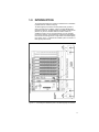
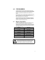
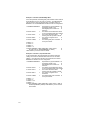
R/W
Reg#
Description
R/0
32
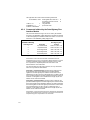
Data Highway Plus station address (0-77 octal). The value comes
from the thumbwheel switches on the faceplate and is updated
only on power-up. The module will not begin to communicate on
the network until the station address is properly set and bit 0 in
register 5 is set by the user. Note that the on-line Monitor function
in the AutoMax Programming Executive software will display the
station address in decimal or hexadecimal notation.
R/0
33
Data Highway Plus Extended Status (EXT STS) error code. Refer
to Appendix H.
R/0
34-37 Data Highway Plus active station list. This is an array of 64 bits
representing the status (1=active, O=inactive) of each station on
a Data Highway Plus network. Refer to Appendix F for information
on how this list is mapped to these registers. The local station
does not appear on this list.
R/0
40-57 Data Highway Plus Diagnostics Counters. Refer to Appendix G.
R/0
61
R/0
62-63 Interface module ID (ASCII ’GTWY’)
38-39 Not used.
58-60 Not used.
Module Software Revision Level. A value of 100 indicates version
1.00, and so on.
Figure 4.2 – Status and Control Register Assignments
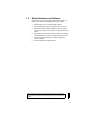
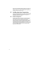
4.1.2
Data Registers
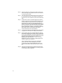
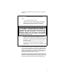
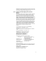
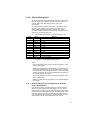
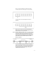
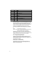
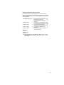
The data image in the dual port memory appears as a subset of the
PLC-5 data table. The equivalent AutoMax and Modicon registers on
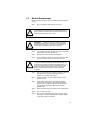
the module are shown in figure 4.3.
Multibus Access
(AutoMax application tasks)
Read Only
Read/Write
Read/Write
Read/Write
Binary file B3
Data Highway Plus
addresses B3:0 - B3:999
AutoMax Registers 64-1063
Binary file B4
Data Highway Plus
addresses B4:0 - B4:999
AutoMax Registers 1088-2087
Binary file B5
Data Highway Plus
addresses B5:0- B5:999
AutoMax Registers 2088-3087
Command Buffer Area
AutoMax Registers 3584-4095
Global Registers Area
AutoMax Registers 4096-4352
Integer file N7
Data Highway Plus
addresses N7;0 - N7:999
AutoMax Registers 4384-5383
Data HighwayPlus
Access
Read/Write
Read Only
Read/Write
Read/Write
Figure 4.3 – PLC-5 Data Image
4-3