1
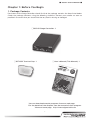
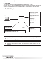
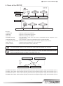
Intelligent Driver
Two-Axis Stage Controller
GSC-02
User's Manual
GSC-02
Notes regarding these materials
・ These materials are intended as a reference to assist our customers in the use of the SIGMA-
KOKI CO., LTD. Product best suited to the customer’s application; they do not convey any
license under any intellectual property rights, or any other rights, belonging to SIGMAKOKI
CO., LTD. or a third party.
・ SIGMAKOKI CO., LTD. assumes no responsibility for any damage, or infringement of any
third-party’s rights, originating in the use of any product data, diagram, charts, programs, or
algorithms contained in these materials.
・ All information contained in these materials, including product data, diagrams, charts, programs
and algorithms represents information on products at the time of publication of these materials,
and are subject to change by SIGMAKOKI CO.,LTD. without notice due to product improvements or other reasons.
・ When using any or all of the information contained in these materials, including product data,
diagrams, charts, programs, and algorithm, please be sure to evaluate all information and
products. SIGMAKOKI CO., LTD. assumes no responsibility for any damage, liability or other
loss resulting from the information contained herein.
・ SIGMAKOKI CO., LTD. products are not designed or manufactured for use in equipment or
system that is used under circumstances in which human life is potentially at stake. SIGMA-
KOKI CO., LTD. products cannot be used for any specific purposes, such as apparatus or
systems for transportation, vehicular, medical, aerospace, nuclear, or undersea repeater use.
・ The prior written approval of SIGMAKOKI CO., LTD. is necessary to reprint or reproduce in
whole or in part these materials.
・ If these products or technologies are subject to the Japanese export control restrictions, they
must be exported under a license Japanese government and cannot be imported into a country
other than the approved destination.
Any diversion or re-export contrary to the export control laws and regulations of Japan and/ or
the country of destination is prohibited.
■ GSC-02 User's Manual ■
Contents
For Your Safety…………………………………………………………………… 2
Chapter 1: Before You Begin… …………………………………………… 3
  1. Package Contents… …………………………………………………………………… 3
  2. Overview…………………………………………………………………………………… 4
  3. The GSC-02 System… ………………………………………………………………… 4
  4. Parts of the GSC-02… ………………………………………………………………… 5
Chapter 2: Basic Operations………………………………………………… 6
  5. GSC-02 Connection procedure……………………………………………………… 6
  6. GSC-02 Setting…………………………………………………………………………… 6
Chapter 3: Using GSC-02 to position Motorized Stages… ……… 9
  7. Using Computer to position Motorized Stages…………………………………… 9
Chapter 4 : Specification…………………………………………………… 14
  8. Specification…………………………………………………………………………… 14
  9. Connector Pin Numbers and Signals… ………………………………………… 15
10. Exterior Dimensions… ……………………………………………………………… 16
1
■ GSC-02 User's Manual ■
For Your Safety
Before using this product, read this manual and all warnings or cautions in the documentation provided.
Only Factory Authorized Personnel should be changes and/or adjust the parts of controller.
The Symbols Used in This Manual
WARNING
CAUTION
This symbol marks warnings that should be read and This symbol indicates where caution should be used to
used to prevent serious injury or death.
avoid possible injury to yourself or others, or damage to
property.
The above indications are used together with the following symbols to indicate the exact nature of the warning or
caution.
Examples of Symbols Accompanying Warnings and Cautions
△ Symbols enclosed in a triangle indicate warnings and cautions. The exact nature of the warning
or caution is indicated by the symbol inside (the symbol at left indicates risk of electrocution).
○ Symbols enclosed in a circle mark indicate prohibitions(actions that must not be performed).
The exact nature of the prohibition is indicates by the symbol inside or next to the circle mark (the
symbol at left indicates that the product must not be disassembled).
● Symbols inside a black circle mark actions that must be performed to ensure safety. The exact
nature of the action that must be performed is indicated by the symbol inside (the symbol at left is
used in cases in which the AC adapter must be unplugged to ensure safety).
Symbols on the product
The symbol mark on the product calls your attention. Please refer to the manual, in the case that you operate the
part of the symbol mark on the product.
This symbol labeled on the portion calls your attention.
Disclaimer of Liability
① SIGMAKOKI CO., LTD. does not accept liability for damages resulting from the use of this product or the inability
to use this product.
② SIGMAKOKI CO., LTD. does not accept liability for damages resulting from the use of this product that deviates
from that described in the manual.
③ SIGMAKOKI CO., LTD. does not accept liability for damages resulting from the use of this product in extraordinary
conditions, including fire, earthquakes, and other acts of God, action by any third party, other accidents, and
deliberate or accidental misuse.
④ If the equipment is used in a manner not specified by the SIGMAKOKI CO., LTD., the protection provided by the
equipment may be impaired.
WARNING
● Do not use this product in the presence of flammable gas, explosives, or corrosive substances, in areas exposed to high levels
of moisture or humidity, in poorly ventilated areas, or near flammable materials.
● Do not connect or check the product while the power is on.
● Installation and connection should be performed only by a qualified technician.
● Do not bend, pull, damage, or modify the power or connecting cables.
● Do not touch the products internal parts.
● Connect the earth terminal to ground.
● Should the product overheat, or should you notice an unusual smell, heat, or unusual noises coming from the product, turn off
the power immediately.
● Do not turn on the power in the event that it has received a strong physical shock as the result of a fall or other accident.
● Do not touch the stage while operation.
● Use dry clothes only for cleaning the equipment.
2
Osaka branch
■ GSC-02 User's Manual ■
Chapter 1: Before You Begin
1. Package Contents
Purchasers of the Stage Controller should fi nd that the package contains the items listed below.
Check  the  package  contents  using  the  following  checklist.  Contact  your  retailer  as  soon  as
possible in the event that you should fi nd that any item is missing or damaged.
□ GSC-02 Stage Controller: 1
GS
SC
CC 02
02
□ SCT-602 Terminal Cap: 1
□ User's Manual (This Manual): 1
Intelli
gent
iver
Two
-Axis
Stag
e Co
ntro
ller
Dr
GSC-0
2
User's
Manu
al
Tel:
http:/
/www
+81-
.sigm
a-koki
.com
-82 28
1-19-9,
Osaka
Midori,
Fax:
+81Bran
3-5 638 SIGMA KO
+81KI Tok
-65 50
6-6 307 ch 4-9
yo Hea
-28 ,
E-m
-48 35
d offic
Nishi-N
ail:int
Kyushu
Fax:
e, Sum
ernati
aka
+81onal@s ida-ku,
Tel:
6-6 307 jima, Yo
+81- Sales
dog
igma-k Tokyo 130
-48 34
92- 481
of
awa-k
-002 1,
oki.co
E-m
-43 00 fice 3-1
u, Os
JAPAN
ail:sal
m
7,
Fax
aka
3-5 638
Tel:
es.osa
: +81- Hie-ma
532 -00
chi,
ka@
92- 481
sigma 11, JA
-43 10 Hakata-k
-koki.c PAN
u,
E-m
om
ail:sal Fukuok
es.kyu a-shi,
kaho,
shu@s Fukuok
Hakus
igma-k a 812 -00
an-shi
14, JA
oki.co
, Ish
PAN
ikawa
m
924 -08
38, JA
PAN
1-1 Ya
tsu
201 4.2.
GSC
Thir
-02
d edit
ion
You can download sample programs from our web page.
For the details of the samples, see the manual of each program.
View our home page http://www.sigma-koki.com
3
■ GSC-02 User's Manual ■
2. Overview
This controller is two axes stage controller featuring stepping motor drivers.
When the GSC-02 is connected to an ordinary personal computer via an RS232C interface, the
stage can be accurately moved to the desired position by simple commands sent from the PC.
3. The GSC-02 System
SGSP15/20/26 series
SGSP40ZF/60ZF series
SGSP40/60YAW series
PC
SGSP-A/B series
GSC-02
RS232C/STR
Cable
D15RP-CA/
DMINIS-CA
Cable
TSDM series
SGSP-ACT series
GOHTM-40 series
HPS series
HDS series
D15RP-CA/
DMINIH-CA
Cable
SJT-02/SCT-602
TAMM series
* You cannot connect SJT-02/SCT-602 and PC to a
GSC-02 controller at the same time.
GOHTM-50/60/70 series
Note that applicable cables and drive current values are depending on the
specifications of stages used. Check if your controller can adequately control desired
devices before forming a system.
You cannot connect SJT-02/SCT-602 and PC to a GSC-02 controller at the same
time. If you connect them in parallel, GSC-02, SJT-02/SCT-602, and/or PC may be
damaged.
4
Osaka branch
■ GSC-02 User's Manual ■
4. Parts of the GSC-02
①POWER LED
②RUN LED
③DIP switch
④RS232C connector
⑤SCT-602 connector
⑧Earth terminal
⑨Power terminal
⑥Stage driving connector (Axis 1)
⑦Stage driving connector (Axis 2)
Functions:
① POWER LED
: Lights up in green when powered.
② RUN LED
: Lights up in red while driving stages.
③ DIP switch
: Makes basic settings for GSC-02.
④ RS232C connector
: This connector is used when the device is controlled from the computer via an
⑤ SCT-602 connector
: This connector is used when controlling with the SJT-02/SCT-602.
RS232C interface.
⑥ , ⑦ Stage driving connector: Connect to the motorized stage of your choice. Supports up to two axes
⑧ Earth terminal
: Should be grounded properly in your environment.
⑨ Power terminal
: Connect to the power source (+24V, 2A).
Turn off a power supply in the case of the connector connection for security.
Make sure to set up and wire the cable supplying DC+24V and GND to the GSC-02 so
that the maximum length of cable is not longer than 2m.
⑪STAGE1 STOP volume
⑬STAGE2 STOP volume
⑩STAGE1 RUN volume
⑫STAGE2 RUN volume
⑩ STAGE1 RUN volume :Volume control adjusting the RUN current output through the stage drive connector. (Axis 1)
⑪ STAGE1 STOP volume:Volume control adjusting the STOP current output through the stage drive connector. (Axis 1)
⑫ STAGE2 RUN volume :Volume control adjusting the RUN current output through the stage drive connector. (Axis 2)
⑬ STAGE2 STOP volume:Volume control adjusting the STOP current output through the stage drive connector. (Axis 2)
5
■ GSC-02 User's Manual ■
Chapter 2: Basic Operations
5. GSC-02 Connection procedure
5-1. Connecting to Motorized Stages
First, connect GSC-02 to the motorized stages.
①Please confirm the power source is turning off.
②Connect a standard cable (DMINIS-CA/DMINIH-CA) to the connector of the motorized stage.
③Connect the stage to be controlled as the first axis to the STAGE1 connector of the GSC-02
controller. Also connect the stage controlled as the second axis to the STAGE2 connector.
5-2. Connecting to PC and peripheral device
Connect GSC-02 to PC and peripherals (SJT-02/SCT-602).
RS232C interface is used for the connection between the PC and GSC-02.
The following descriptions premise the RS232C interface.
①Please confirm the power source is turning off.
②Use a genuine cable RS232C/STR, or 9-pin, D-SUB straight cable with male/female ends using
inch screw threads.
③Insert the male connector of communications cable in to the RS232C connector on the GSC02. Insert the female end into the serial port on your PC.
6. GSC-02 Setting
Initialize your GSC-02 to match to the target stages and host environment (your PC, etc). The
initialization includes DIP Switch settings and current adjustments (RUN/STOP) for each axis
motor.
6-1. Set parameters with DIP Switch
Initialize your GSC-02 by setting each switch to ON/OFF as follows:
Parameter Assignment in the DIP Switch:
DIP Switch No.
1,2
Items
Parameters
Baud rate
2400/4800/9600/19200
3
Detecting the mechanical origin
MARK method/MINI method
4
Input logic for the limit sensor
Normal open/ Normal close
5
Specify whether to return mechanical origin
First axis only/ Both axis
for each axis
6
Osaka branch
■ GSC-02 User's Manual ■
Switch settings and Corresponding Parameters (Set to ON by turning to the down side)
Items
Dip Switch No.
Descriptions
SW No.2
SW No.1
ON
ON
2400bps
ON
OFF
4800bps
OFF
ON
9600bps
OFF
19200bps
Baud rate
OFF
SW No.3
Detecting the
mechanical origin
ON
MARK method
OFF
MINI method
SW No.4
Input logic for the
limit sensor
ON
Normal open
OFF
Normal close
SW No.5
Specify whether to
return mechanical
origin for each axis
ON
First axis only
OFF
Both axis
(Note) Shaded areas in the list show our factory settings. Tale care to handle the very small DIP
Switch so as to avoid giving damage to them during the settings. Use appropriate tools
such as sharp tweezers for setting switches on the DIP Switch. For our SGSP series
stages, select Normal close for the limit sensor logic and MINI for the homing method.
Detecting the Mechanical Origin:
MINI method
CW sensor
5000PPS CW (−)
CW LS detection
5000PPS CCW (+)
Move 1000 pulse
500PPS CW (−)
CW LS detection
5000PPS CCW (+)
Move 1000 pulse
MARK method
ORG sensor
5000PPS
NEAR sensor
CW(−)
CW sensor
CW LS detection
500PPS
50PPS
CCW(+)
7
N sensor detection
CCW (+)
O sensor detection
■ GSC-02 User's Manual ■
6-2.Setting the drive current
Set current values supplied from GSC-02 to stages. Turn a RUN current volume, provided on the
side of the unit, to adjust RUN current corresponding to the stages to use. Use a STOP current
volume to set a ratio to RUN current according to your conditions
for the case where the current down function works. You can make
each current adjustment for Axis 1 or Axis 2 independently.
Note that for the STOP current, adjustment is available not for
current values, but for a ratio(%) to the RUN current.
Note) Generally the ratio of the STOP current to the RUN current
Volume
is approx. 50%.
Driving current settings (RUN)
Factory-set to 0.35A/Phase
Volume No.
0
1
2
3
4
5
6
7
8
9
10
RUN current
(A/phase)
0.3
0.31
0.32
0.33
0.4
0.5
0.6
0.68
0.75
0.79
0.8
Stop current settings (STOP current setting to 50% for RUN current)
Factory-set to volume No.0
RUN No.
0
1
2
3
4
5
6
7
8
9
10
STOP No.
0
0
0
0
1
1
2
2
3
3
3
Note) Each value cited in the above table is a guide to adjust the current without instrument,
and may fluctuate within an allowable range.
6-3.Power ON
When you have completed procedures above, connect the power source. GSC-02 is power ON
and the green power LED lights up.
Now the setup has been done, and your GSC-02 is ready to use. For the details of commands
applicable to GSC-02, see Chapter 3.
8
Osaka branch
■ GSC-02 User's Manual ■
Chapter 3: Using GSC-02 to position Motorized Stages
7. Using Computer to position Motorized Stages
The controller can be connected to a computer using an RS232C interface. Motorized stages can
then be precisely controlled by commands (strings) transmitted from the computer.
The RS232C interface communication parameter of the GSC-02 is described below. Please set
the configurations of the PC side according to the following table.
Items
Descriptions
Baud rate
Baud rate set with DIP Switch
Delimit
CR+LF
Parity
Non
Data bit
8bit
Stop bit
1bit
Flow control
Hardware (RTS/CTS)
7-1. List of Commands
The following is a list of available commands:
Command
String
Details
Return to mechanical origin
H:
Detect mechanical origin
Set number of pulses for
relative movement
M:
Axis of movement, direction, number of
pulses
Jog command
J:
Move at minimum speed (S)
Drive command
G
Start
Stop command
L:
Stop
Set electronic (logical) origin
R:
Set the electronic (logical) origin to the
current position
Speed settings
D:
Set S, F and R
Free motor
C:
Excitation ON/OFF
Status1
Q:
Return current position etc.
Status2
!:
Return B(busy)/R(ready)
Internal information
?:
Check internal information
7-2. Command Format
Except for some status check commands (Q:, !:, ?:), no response will be returned to a command
input. To determine whether or not a command was received normally, use the Q command to
check status.
9
■ GSC-02 User's Manual ■
7-3. Commamd in Detail
(1) H command: Return to mechanical origin
Features:This command is used to detect the mechanical origin for a stage and set that position
as the origin. Once the mechanical origin has been detected, the value displayed
will be 0. Each axis moves at the following constant conditions: Minimum speed (S):
500PPS, Maximum speed (F): 5000PPS, Acceleration/ Deceleration time (R): 200mS.
Axes to home are depending on the DIP Switch settings.
Format:
H: 1+
Detects mechanical origin for Axis 1 in the positive direction.
H: 1-
Detects mechanical origin for Axis 1 in the negative direction.
H: 2+
Detects mechanical origin for Axis 2 in the positive direction.
H: 2-
Detects mechanical origin for Axis 2 in the negative direction.
H: W++
Detects mechanical origin for Axis 1 in the positive direction, and Axis 2 in the
positive direction.
H: W+-
Detects mechanical origin for Axis 1 in the positive direction, and Axis 2 in the
negative direction.
H: W-+
Detects mechanical origin for Axis 1 in the negative direction, and Axis 2 in the
positive direction.
H: W--
Detects mechanical origin for Axis 1 in the negative direction, and Axis 2 in the
negative direction.
(2) M command: Set number of pulses for relative travel
Features:This command is to specify the axis of travel, direction, and the travel (number of
pulses). This command must always be followed by a drive (G) command. Travel is by
means of acceleration/deceleration driving.
Format:
M: nmPx
Parameter:
n: 1 or 2 or W
Axis number
1 or 2: Moves only one axis, W: Moves both axes.
m: + or -
Direction of move
+: + direction move, -: - direction move
x: moving pulse count
0 - 16777214.
Example:
M: W+P500-P200
Travel 500 pulses in the + direction on the first axis
G direction on the second axis
and 200 pulses in the -
10
Osaka branch
■ GSC-02 User's Manual ■
(3) J command: JOG
Features:This command drives stages continuously (at a constant speed) at the starting speed
(S). This command must always be followed by a drive (G) command. The stage will
stop by an L command.
Format:
J: nm
Parameter:
n : 1 or 2 or W
Axis number
1 or 2: Moves only one axis, W: Moves both axes.
m : + or -
Direction of move
+: + direction move, -: - direction move
Example:
J:W-+
Move in the - direction on the first axis and in the + direction on the second
G
axis
(4) G command: Drive
Features: When a drive command is issued, the stage starts moving, moves the specified
number of pulses, and then stops. The G command is used after M and J commands.
Format:
G Drive
(5) L command: Decelerate and stop
Features:When this command is executed, the stage decelerates and stops.
Format:
L: 1 First axis decelerates and stops
L: 2 Second axis decelerates and stops
L: W
First- and second-axis decelerate and stop
Note) Stage does not stop even if“L:1”,“L:2”at the time“H:W”
.
Stop in“L:W" or“L:E".
(6) L: E command: Emergency stop
Features: This command stops all stages immediately, whatever the conditions.
Format:
L: E Stop first and second axes immediately
11
■ GSC-02 User's Manual ■
(7) R command: Set electronic (logical) origin
Features:This command is used to set electronic (logical) origin to the current position of each
axis.
Format:
R: 1
Set the electronic (logical) origin for the first axis
R: 2
Set the electronic (logical) origin for the second axis
R: W
Set the electronic (logical) origins for the first- and second-axis
(8) D command: Speed settings
Features:The minimum speed (S), maximum speed (F), and acceleration/deceleration time (R)
are set according to the initialize settings when the power is turned on. This command
allows you to change these initial settings. The initialize setting is (S): 500PPS, (F):
5000PPS, (R): 200mS.
Format:
D: rSspd11Fspd21Rspd31Sspd12Fspd22Rspd32
Parameter:
r: 1 or 2 Speed range
1: Low speed range, 2: High speed range
spd1
Minimum speed(S)
1 – 200PPS (Low range), 50 – 20000PPS (High range)
spd2
Maximum speed(F)
1 – 200PPS (Low range), 50 – 20000PPS (High range)
spd3
Acceleration/ Deceleration time (R)
0 – 1000mS (for both High/Low range)
Note) The maximum speed(F) setting should be equal or greater than the minimum speed. If the
minimum speed is set to equals to the maximum or the acceleration/ deceleration time
is set to zero, stages will move at a constant speed without performing acceleration/
deceleration logically.
Example:
D: 2S100F1000R200S100F1000R200
Sets speeds for Axes1 and 2: Axis1: S = 100PPS, F = 1000PPS, R = 200mS, Axis2: S =
100PPS, F = 1000PPS, R = 200mS.
Acceleration and Deceleration Patterns
Maximum pulse
speed (F)
Minimum pulse
speed (S)
Acceleration
time (Rms)
Number of
pulses moved
Positioning time
12
Osaka branch
Deceleration
time (Rms)
■ GSC-02 User's Manual ■
(9) C command: Free/ hold motor (Excitation ON/OFF)
Features:This command is used to excite the motor or to turn excitation off, making it possible
to move (rotate) stages manually.
Format:
C: nm
Parameter:
n: 1 or 2 or W
Axis number
1 or 2: only one axis, W: both axes.
m: 0 or 1
0: motor free, 1: motor hold
Example: C: 10 Free first-axis motor
(10) Q command: Status 1
Features:On receipt of this command, the controller returns the coordinates for each axis and
the current state of each stage.
Format:
Q: Return data:
- 100, - 200, ACK1, ACK2, ACK3
First-axis
coordinates
Second-axis
coordinates
Three-character
string data
ACK1… ……… X: Command or parameter errors.
K: Command received normally.
ACK2… ……… L: First axis stopped at LS
M: Second axis stopped at LS
W: First and second axes stopped at LS
K: Normal stop
ACK3… ……… B: (BUSY) L, Q ,and ! commands can be received
R: (READY) all commands can be received
※ Coordinate values for each axis have a fixed length of ten digits, including sign
(Sign is left-aligned, coordinates values right-aligned).
(11) ! command: Status 2
Features:On receipt of this command, the controller returns the stage operating status.
Format: !:
Return data:
B
(BUSY) L, Q and ! commands can be received
R
(READY) all commands can be received
(12) ? command: Request for internal information
Features: The command to request an internal ROM version from the controller.
Format:
?: V
Return data example:
V2.00
Internal ROM version 2.00
1: active
13
■ GSC-02 User's Manual ■
Chapter 4 : Specification
8. Specification
(1) General specifications
Power source DC+24V
Rating current 2A
Operating temperature 5 to 40 ℃
Storage temperature -20 to 60 ℃
Altitude up to 2000m
Indoor use only
Installation category Ⅱ
Pollution degree 2
Ambient humidity
20 to 80%RH (no condensation)
External dimensions 180W x125D x40H (excluding projections)
Weight
0.7kg
(2) Performance
Controlling axis 2 axis
Maximum driving speed (F) 1 to 20kPPS
Minimum driving speed (S) 1 to 20kPPS
Acceleration/deceleration time (R) 0 to 1000ms
Sensor input Origin sensor/proximity sensor/CW (-) limit/CCW (+) limit
(Limit sensor logic can be changed with the settings of switch 4 on the DIP Switch.)
Method of return to origin
Axes to Home
Interface MINI method/MARK method
(Set with switch 3 on the DIP Switch.)
Axis1/ both axis (1axis and 2axis)
(Set with switch 5 on the DIP Switch.)
RS232C interface
Communication Parameters
- Baud rate
(Set with switches 1/2 on the DIP Switch.)
- Data bits 8 bits
- Parity None
- Stop bit 1bit
- Flow control Hardware (RTS/CTS)
- Delimiters CR+LF
2400/4800/9600/19200
(3) Driver Specifications
Driver Mode Half step driving
Driving (RUN) current 0.3A/phase to 0.8A/phase
Current down function Automatic current down
(4) Electrical fast transmit/burst immunity EN61000-4-4 (2004) Level2
(5) Electrostatic discharge EN61000-4-2 (1995)+A1 (1998)+A2 (2001) Level2.
14
Osaka branch
■ GSC-02 User's Manual ■
9. Connector Pin Numbers and Signals
9-1. STAGE1, 2 Connector
No.
Name
No.
Name
1
Blue: motor wiring
9
GND: for Brake
2
Red: motor wiring
10
+24V: for Brake
3
Orange: motor wiring
11
LS (+): limit detection on +
4
Green: motor wiring
12
LS (-): limit detection on-
5
Black: motor wiring
13
GND: common sensor
6
GND: common sensor
14
NEAR: proximity detection
7
ORG: mechanical origin detection
15
+24V: sensor power supply
8
+24V: sensor power supply
Connector Type D-sub 15pin female connector (mm screw threads)
9-2. RS232C Connector
No.
Name
No.
Name
1
-
6
DTR
2
TxD
7
CTS
3
RxD
8
RTS
4
DSR
9
-
5
SG
Connector Type D-sub 9pin female connector (inch screw threads)
9-3. SCT602 Connector
No.
Name
No.
Name
1
+24V
6
DTR
2
TxD
7
CTS
3
RxD
8
RTS
4
DSR
9
Reserved
5
SG
Connector Type D-sub 9pin male connector (mm screw threads)
Do not connect any other devices to the SCT602 connector to avoid possible damage.
You cannot connect to the SCT602 connector and RS232C connector at the same time.
15
■ GSC-02 User's Manual ■
10. Exterior Dimensions
3-M3 fixing hole (threaded)
16
Osaka branch
http://www.sigma-koki.com
1-19-9, Midori, SIGMA KOKI Tokyo Head office, Sumida-ku, Tokyo 130-0021, JAPAN
Tel: +81-3-5638-8228 Fax: +81-3-5638-6550 E-mail:international@sigma-koki.com
Osaka Branch
4-9-28, Nishi-Nakajima, Yodogawa-ku, Osaka 532-0011, JAPAN
Tel: +81-6-6307-4835 Fax: +81-6-6307-4834 E-mail:sales.osaka@sigma-koki.com
Kyushu Sales office
3-17, Hie-machi, Hakata-ku, Fukuoka-shi, Fukuoka 812-0014, JAPAN
Tel: +81-92-481-4300 Fax: +81-92-481-4310 E-mail:sales.kyushu@sigma-koki.com
1-1 Yatsukaho, Hakusan-shi, Ishikawa 924-0838, JAPAN
2014.2. Third edition


![User's Guide [Advanced Scan Operations]](http://vs1.manualzilla.com/store/data/006865872_1-8b3a85e3ed58d035968500e47824ff56-150x150.png)