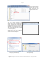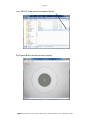
1
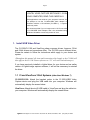
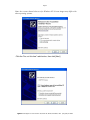
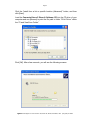
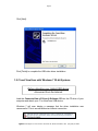
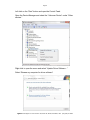
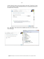
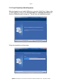
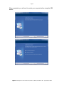
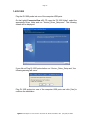
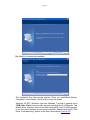
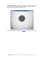
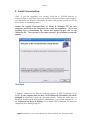
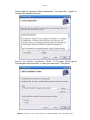
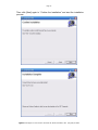
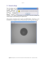
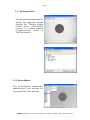
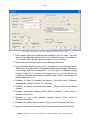
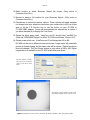
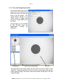
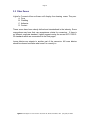
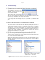
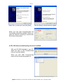
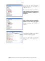
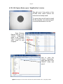
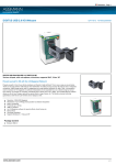
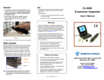
TM
ConnectorView v3.1
Video Capture Software
For CI-1000-USB2, ViewConn® and DI-1000
Installation &
User’s Manual
1. Install USB Video Driver
…………………………..….……..…
Page 2
1.1 CI-1000/CI-1100 and ViewConn ..… Page 2
(other than Windows 7) 32-bit
1.2 CI-1000/CI-1100 and ViewConn ..… Page 5
(Windows 7) 32-bit
1.3 CI-1000/CI-1100 and ViewConn .… Page 8
(All versions) 64-bit
1.4 DI-1000
………………………………………….
Page 10
2. Install Lightel’s ConnectorView Software ….…….. Page 13
3. Using Lightel’s ConnectorView Software .……..….. Page 16
3.1 General Settings
3.2 Fiber Zones
…………..……….………
Page 16
………………..….…….……...….
Page 21
3.3 Digital Zoom (DI-1000)
.…..….……...…
Page 26
3.4 Capturing Video Images
…..…..……..
Page 27
4. Troubleshooting
………………………………………….…………
This software has been tested on computers with USB1.1 or USB 2.0 ports;*
Windows 2000® SP4, Windows XP® SP2, Windows Vista® and Windows 7® Operating Systems.
*USB 2.0 port is necessary for full functionality.
ConnectorView 3.1 Rev D
Page 30
Page 2
IF YOU HAVE PREVIOUSLY INSTALLED
LIGHTEL VIDEO CAPTURE SOFTWARE 1.22 ON
YOUR COMPUTER, READ THIS CAREFULLY.
Both applications can reside on your computer; however, do
not attempt to use the CI-1000-USB2 Video Adapter or
ViewConn with the v1.22 software (for USB1.1). A system
crash may result.
We recommend that if you no longer need v1.22 for use with
a CI-1000-USB Video Adapter, that it be uninstalled using
Windows Uninstaller to avoid any chance of error.
1. Install USB Video Driver
The CI-1000/CI-1100 and ViewConn share common drivers, however, 32-bit
and 64-bit drivers and procedures differ. The DI-1000 uses a different driver.
Please be certain to follow the instructions which apply to your device and
system.
(Throughout this manual, all items and instructions which apply to the CI-1000 will
also apply to the CI-1100. Future references to “CI” will cover both videoscopes.)
If you have previously installed a Lightel driver for your device and an earlier
version of Lightel image capture software, it will not be necessary to reinstall
the driver.
1.1 CI and ViewConn 32-bit Systems (other than Windows 7)
CI-1000/CI-1100: Attach the handset probe to the CI-1000-USB2 Video
Capture device and plug the USB cable into your computer. Windows will
automatically display the screen below.
ViewConn: Attach the mini-B USB cable to ViewConn and plug the cable into
your computer. Windows will automatically display the screen below.
Lightel Technologies Inc. 2210 Lind Ave. SW, Suite 100, Renton, WA 98057, USA (Tel) (425) 277-8000
Page 3
Note: the screens shown below are for Windows XP. Screen images may differ with
other operating systems.
Click the “No, not this time” radio button, then click [Next].
Lightel Technologies Inc. 2210 Lind Ave. SW, Suite 100, Renton, WA 98057, USA (Tel) (425) 277-8000
Page 4
Click the “Install from a list or specific location (Advanced)” button, and then
click [Next].
Load the ConnectorView v3 Driver & Software CD into the CD drive of your
computer and use [Browse] to point the file path to folder “32-bit Driver” within
the “CI and ViewConn Folder”.
Click [OK]. After a few seconds, you will see the following screens.
Lightel Technologies Inc. 2210 Lind Ave. SW, Suite 100, Renton, WA 98057, USA (Tel) (425) 277-8000
Page 5
Click [Next].
Click [Finish] to complete the USB video driver installation.
1.2 CI and ViewConn with Windows 7 32-bit Systems
Before attaching your Lightel USB device,
disconnect from the Internet.
Load the ConnectorView v3 Driver & Software CD into the CD drive of your
computer and attach your CI or ViewConn USB device.
Windows 7 will soon display a message that the driver installation was
unsuccessful. This is normal without an Internet connection.
Lightel Technologies Inc. 2210 Lind Ave. SW, Suite 100, Renton, WA 98057, USA (Tel) (425) 277-8000
Page 6
Left click on the “Start” button and open the Control Panel.
Open the Device Manager and select the “Unknown Device” under “Other
devices.”
Right click to open the menu and select “Update Driver Software…”
Select “Browse my computer for driver software”
Lightel Technologies Inc. 2210 Lind Ave. SW, Suite 100, Renton, WA 98057, USA (Tel) (425) 277-8000
Page 7
Use the “Browse” button to point the file path to the folder “32-bit Driver” within
the “CI and ViewConn Folder” and then left click on it so that the path shows in
the address bar. Click [Next].
The USB 2860 video driver will be installed and will now be listed in your
Device Manager.
Lightel Technologies Inc. 2210 Lind Ave. SW, Suite 100, Renton, WA 98057, USA (Tel) (425) 277-8000
Page 8
1.3 CI and ViewConn 64-bit Systems
Without plugging in your Lightel USB device, open the “64-bit Driver” folder in the
“CI and ViewConn” folder on the ConnectorView v3.1 Software and Driver CD.
Click on “EM28xxDriver64_Setup.exe.” This will start the installation process.
Follow the instructions on the screen.
Lightel Technologies Inc. 2210 Lind Ave. SW, Suite 100, Renton, WA 98057, USA (Tel) (425) 277-8000
Page 9
When completed, you will need to restart your computer before using the USB
device.
Lightel Technologies Inc. 2210 Lind Ave. SW, Suite 100, Renton, WA 98057, USA (Tel) (425) 277-8000
Page 10
1.4 DI-1000
Plug the DI-1000 probe into one of the computer USB ports.
On the Lightel ConnectorView v3.1 CD, open the “DI-1000 folder”, select the
appropriate Driver folder and run “Vimicro_Driver_Setup.exe”. The following
screen will be displayed.
If you did not Plug DI-1000 probe before run “Vimicro_Driver_Setup.exe”, the
following warning will occur.
Plug DI-1000 probe into one of the computer USB ports and click [Yes] to
continue the installation.
Lightel Technologies Inc. 2210 Lind Ave. SW, Suite 100, Renton, WA 98057, USA (Tel) (425) 277-8000
Page 11
Click [Next] to continue the installation.
This installation may take several minutes. When the “InstallShield Wizard
Completed” screen shows, click [Finish] to close the wizard.
Windows XP SP2, Windows Vista and Windows 7 provide a camera driver
(USB Video Class) for some video cameras including the DI-1000 probe. This
default driver, however, does not provide functionality for all DI-1000 features.
If you find some features on your probe unusable, please check the“DI-1000
Driver Troubleshooting” section at the end of this manual (Section 4.3.)
Lightel Technologies Inc. 2210 Lind Ave. SW, Suite 100, Renton, WA 98057, USA (Tel) (425) 277-8000
Page 12
Note for 64-bit systems: The portion of the driver which controls the DI-1000
capture button does not self install on these systems. Instead pressing the
button will open a new window “Snap Shot View.”
Follow the directions in Troubleshooting Sec 4.5 to correct the button function.
Lightel Technologies Inc. 2210 Lind Ave. SW, Suite 100, Renton, WA 98057, USA (Tel) (425) 277-8000
Page 13
2. Install ConnectorView
(Note: If you are upgrading your existing ViewConn or CI-1000 software to
ConnectorView or if you have a previous version of ConnectorView on your computer,
you should first use Windows Uninstaller to remove that previous version. It will not
be necessary to reinstall the driver.)
Locate the Lightel „ConnectorView v3 Driver & Software CD‟ on your
computer, and click on the Setup.exe file to start the installation. (If you are
installing from a downloaded file, extract the zipped file and click on the
Setup.exe file. Then proceed in the same manner.) An installation screen will
appear: *
Click [Next].
* Lightel’s ConnectorView software needs the support of .NET Framework 2.0 or
higher. If your computer does not have .NET Framework 2.0 installed, you will be
prompted to download it from the Microsoft website. Follow the instructions to
download and then finish the installation. Alternatively, you can run “dotnetfx.exe” in
the ConnectorView Driver & Software CD to install .NET Framework 2.0 onto your
computer before running Setup.exe.
Lightel Technologies Inc. 2210 Lind Ave. SW, Suite 100, Renton, WA 98057, USA (Tel) (425) 277-8000
Page 14
Please read the Freeware License Agreement. You must click “I Agree” to
continue the installation process.
Accept the default installation folder “C: \Program Files\Lightel
Technologies\ConnectorView\” or select your own folder. Click [Next].
Lightel Technologies Inc. 2210 Lind Ave. SW, Suite 100, Renton, WA 98057, USA (Tel) (425) 277-8000
Page 15
Then click [Next] again to “Confirm the Installation” and start the installation
process.
Lightel Technologies Inc. 2210 Lind Ave. SW, Suite 100, Renton, WA 98057, USA (Tel) (425) 277-8000
Page 16
3.1 General settings
The CI probe and the
CI-1000-USB2 Video
Adapter, ViewConn or
the DI-1000 mu st b e
p ro p e rly
co n n e cte d
to
yo u r
com put e r
be for e opening the
software. If you observe this window, you will need to close the software and
should reopen it after attaching your Lightel device.
After properly connecting the CI probe and USB Adapter, ViewConn or the
DI-1000 to your computer, click the “ConnectorView” icon to open the software.
Lightel Technologies Inc. 2210 Lind Ave. SW, Suite 100, Renton, WA 98057, USA (Tel) (425) 277-8000
Page 17
3.1.1 Set Image Folder
You can set your folder location for
saving the captured images
through the “File/Set Image
Folder” menu. (The default
location is a newly created
“ConnectorView”
folder
in
“My Documents”.)
3.1.2 Select Options
The “Tools/Options” window will
control m o st o f yo u r c h o i ce s f o r
ConnectorView Plus settings.
Lightel Technologies Inc. 2210 Lind Ave. SW, Suite 100, Renton, WA 98057, USA (Tel) (425) 277-8000
Page 18
13
8
7
14
9
10
1
11
2
3
4
12
5
6
Items numbered in blue are only active and available in ConnectorView Plus
1. These sliders adjust the brightness and contrast of the live video. They will
also set the brightness and contrast for your captured images. The sliders do
not, however, affect already captured images or a frozen screen.
2. These radio buttons enable you to select the image file format.
3. Type a Filename Prefix in the box. Up to 18 characters of the Filename will be
visible (plus a 4 digit number), although Filenames can be longer. Numbering
of the image files will be sequential. You can type in a different starting
number if desired. If you have not already done so, you should set the
location of the saved images using “Files/Set Image Folder” or the Image File
Folder address box (11).
4. Checkbox to select or deselect the display of the fiber zones. (Checked
automatically if analysis feature (7) is checked.)
5. Checkbox to display multimode fiber zones.
setting.)
(Single mode is the default
6. Checkbox used when analyzing MPO (MTP) connectors.
ConnectorView Plus.)
(Only active in
7. Checkbox to turn on/off pass/fail analysis feature. (Only active in
ConnectorView Plus.)
8. Checkbox to create a summary report. (Only active in ConnectorView Plus.)
9. Type in a name for the Summary Report. (Only active in ConnectorView Plus.)
Lightel Technologies Inc. 2210 Lind Ave. SW, Suite 100, Renton, WA 98057, USA (Tel) (425) 277-8000
Page 19
10. Radio buttons to select Summary Report file format. (Only active in
ConnectorView Plus.)
11. Browse to select a file location for your Summary Report. (Only active in
ConnectorView Plus.)
12. Checkboxes to select the capture options. These options will toggle between
live images and your selections here when you mouse click in the Live Video
area or hit the F12 function key or use the button on your DI-1000 or
CI-1000-USB2 adapter. Freeze will automatically be selected as an option if
you have checked (4) to display the Test Zones.
13. Shows the driver being used. ViewConn and CI should show “em2860” for
32-bit and “WDM 2860 Capture” for 64-bit. DI-1000 should show “Vimicro UVC”.
14. Shows screen pixel size. ViewConn and CI will always be 640 x 480.
DI-1000 can be set to different screen pixel sizes. Larger sizes will potentially
provide a sharper image, but the frame rate will be slower. (Optical resolution
does not change.) The Test Zones feature is only active at 640 x 480. Digital
magnification is available on the DI-1000 at all other pixel sizes.
DI-1000 Options window
showing screen resolution
choices from drop down
menu.
DI-1000 Live Video window at 800 x 600
with digital magnification controls active.
Lightel Technologies Inc. 2210 Lind Ave. SW, Suite 100, Renton, WA 98057, USA (Tel) (425) 277-8000
Page 20
3.1.3 Turn on/off Image Explore (F9)
The Image Explore area can be
turned on or off, so that the Live
Video area uses only the right
area or the full screen. Use
“Image Explore On/Off” in the
“Tools” menu to toggle back
and forth. Image explore is off
by default.
(Image Explore is not available
in the DI-1000 when the
Magnification
Controls
are
displayed.)
Image Explore
File Path of Captured Image
Live Video
The right area of the screen shows the live video from the CI-1000 or from
ViewConn. The left area shows the file list of the current image folder and the
latest captured image. The bottom status area shows the file path of the last
captured image.
Lightel Technologies Inc. 2210 Lind Ave. SW, Suite 100, Renton, WA 98057, USA (Tel) (425) 277-8000
Page 21
3.2 Fiber Zones
Lightel‟s
A.
B.
C.
D.
ConnectorView software will display four cleaning zones. They are:
Core
Cladding
Adhesive
Contact
These zones have been clearly defined and standardized in the industry. Some
corporations may have their own acceptance criteria for connectors. If there is
no different corporate standard, Lightel suggests using the current IEC 61300-335 standards which are summerized in the next pages.
Loose debries can migrate to another part of the connector. All loose debries
should be cleaned no matter what zone it is currently in.
Lightel Technologies Inc. 2210 Lind Ave. SW, Suite 100, Renton, WA 98057, USA (Tel) (425) 277-8000
Page 22
3.2.1 Understanding Zones
Single mode fiber requirements
Zone name
(diameter)
A: Core
(0-9μm, 0-25μm)
B: Cladding
(25-120μm)
C: Adhesive
(120-130μm)
D: Contact
(130-250μm)
Scratches
Defects
None
None
No limit
Any < 2μm
5 from 2 - 5μm
None > 5μm
No limit
No limit
No limit
None ≥ 10μm
Note 1: For scratches, the requirement refers to width.
Note 2: No visible subsurface cracks in the core or cladding zones
Note 3: All loose particles should be removed. If defect(s) are non-removable, it
should be within the criteria above to be acceptable for use.
Note 4: There are no requirements for the area outside the contact zone since defects in
this area have no influence on performance. Cleaning loose debris beyond this region is
recommended good practice.
Core (A)
Cladding (B)
Adhesive (C)
Contact (D)
Lightel Technologies Inc. 2210 Lind Ave. SW, Suite 100, Renton, WA 98057, USA (Tel) (425) 277-8000
Page 23
Multimode fiber requirements
Zone name
(diameter)
A: Core
(0-65μm)
Scratches
Defects
No limit ≤ 3μm
None > 3μm
B: Cladding
(65-120μm)
No limit ≤ 5μm
None > 5μm
4 ≤ 5μm
None > 5μm
Any < 2μm
5 from 2 - 5μm
None > 5μm
C: Adhesive
(120-130μm)
D: Contact
(130-250μm)
No limit
No limit
No limit
None ≥ 10μm
Note 1: For scratches, the requirement refers to width.
Note 2: No visible subsurface cracks in the core or cladding zones
Note 3: All loose particles should be removed. If defect(s) are non-removable, it
should be within the criteria above to be acceptable for use.
Note 4: There are no requirements for the area outside the contact zone since defects in
this area have no influence on performance. Cleaning loose debris beyond this region is
recommended good practice.
Core (A)
Cladding (B)
Adhesive (C)
Contact (D)
Lightel Technologies Inc. 2210 Lind Ave. SW, Suite 100, Renton, WA 98057, USA (Tel) (425) 277-8000
Page 24
3.2.2 Using Display Fiber Zones Feature
Lightel‟s ConnectorView software is designed to automatically locate the
ferrule and display the zones even when the image is not properly centered.
This can help you ensure that the contact zone is completely visible.
If a connector is too dirty, the automatic detection may not function properly. In
this situation you can clean the connector and retry, or you can use “Manual
Zone Adjustment” to correct the ring placement.
Lightel Technologies Inc. 2210 Lind Ave. SW, Suite 100, Renton, WA 98057, USA (Tel) (425) 277-8000
Page 25
To adjust the target manually,
click
“Tools/Manual
Zone
Adjustments” or press the
[F11] function key on your
keyboard.
Use your mouse cursor to drag the red
target to the right position, then use the
red controls for size adjustment and fine
adjustments.
Click the “Zone” button to display the
Zone rings and make any final
adjustments. You can use the F10
function key to save your finished result.
Clicking the “Live” button will return you to
a live screen, but keep the adjustment
controls visible. (You cannot use the
controls with the live video.) Clicking the
“Exit” button will return you to live video
without saving any of your adjustments.
Lightel Technologies Inc. 2210 Lind Ave. SW, Suite 100, Renton, WA 98057, USA (Tel) (425) 277-8000
Page 26
3.3 Digital Magnification (DI-1000 only)
If you wish to activate digital
magnification (digital zoom)
on the DI-1000, open the
“Options” window, and use
the dropdown menu to
select a different Video
Format (not 640 x 480).
The Zones feature will be disabled,
but the Zooming Panel will be
activated. This panel can be turned
on or off from the “Tools” menu or by
using the [F11] function key.
The green arrows allow you to recenter the image if zooming has
moved it out of position.
The yellow button will show the
current level of digital magnification.
The image can be frozen, but will be
captured
at
the
true
optical
magnification level.
To return to the default 640 x 480 setting, open the “Options” window again and
select that setting. If you had previously checked “Zones” this feature will again
be active.
Lightel Technologies Inc. 2210 Lind Ave. SW, Suite 100, Renton, WA 98057, USA (Tel) (425) 277-8000
Page 27
3.4 Capturing Video Images
There are several ways to capture a video image: by mouse-clicking the Live
Video area, by clicking the CI-1000-USB2 Adapter Capture Button or the DI-1000
Capture Button, by clicking “Capture” under the menu “Tools”, by pressing the
[F12] function key on the computer keyboard, or by pressing the [F10] function key.
3.4.1 Capture Image by Mouse-Clicking the Live Video Area
Clicking on the Live Video area once will freeze, capture, or freeze and
capture the image depending on how you have set the checkboxes in
“Options”. This frozen image is captured and its filename is displayed in the
upper left corner of the area. (The red letters will not appear on the saved
image.)
When using the Image Explore mode, the filename is also added to the file list
in Image Explore, and the small image on the top is updated. The bottom
status line indicates the file path of the captured image file.
If you have clicked the “Display Fiber Zones” checkbox, the zones will be
displayed on the frozen image and captured (if applicable).
To return the Live Video area back to live mode, simply click on that area again.
You can browse the image list in Image Explore to review your captured images
in the small image area at the top. By clicking this small image, that image will
replace the image displayed in the Live Video area. Clicking on the Live Video
area again, returns the screen to live mode.
Lightel Technologies Inc. 2210 Lind Ave. SW, Suite 100, Renton, WA 98057, USA (Tel) (425) 277-8000
Page 28
3.4.2 Capture Image using Keyboard [F12]
Pressing the [F12] key functions the same way as Mouse-clicking (see 3.4.1
for details). Pressing the button once will freeze, capture, or freeze and
capture the image, depending upon how you have marked the checkboxes.
Pressing the [F12] key a second time returns the screen to the live mode.
3.4.3 Capture Image using CI-1000-USB2 Adapter Capture Button
Pressing the USB Adapter Button functions the same as the Mouse-click
method or [F12] method.
3.4.4 Capture Image using DI-1000 Probe Capture Button
Pressing the probe Capture Button functions the same as the Mouse-click
method or [F12] method.
3.4.5 Capture Image from Menu “Tools/Capture”
Clicking “Capture” under the “Tools” menu is another way to capture an image.
It will always capture the image no matter what you have checked in the
“Options” window. To return to a live image, mouse-click on the screen, press
the [F12] key, or press the CI-1000-USB2 Adapter button or DI-1000 probe
Capture Button.
3.4.6 Capture Image using Keyboard [F10]
Pressing the function key [F10] captures an image each time the key is
pressed. As with the “Tools/Capture” method, the [F10] key is independent of
the “Options” setting. To return to a live image, mouse-click on the screen,
press the [F12] key, or press the CI-1000-USB2 Adapter button or DI-1000
probe Capture Button.
Capture Summary
Mouse-clicking, the [F12] key, the USB Adapter Button and the probe
Capture Button toggle between the live image and your “Options” checkbox
settings.
“Tools/Capture” and the [F10] key are independent of the “Options” settings
and will always capture the image.
Lightel Technologies Inc. 2210 Lind Ave. SW, Suite 100, Renton, WA 98057, USA (Tel) (425) 277-8000
Page 29
Function Key Summary
F9 – Image Explore On/Off
F10 – Capture and Save Image
F11 – (for CI and ViewConn) Manual Zone Adjustments On/Off
(for DI-1000)
Manual Zone Adjustments On/Off (640 x 480 video resolution)
Zooming Panel On/Off (other video resolutions)
F12 – Live/Options Setting Toggle
Lightel Technologies Inc. 2210 Lind Ave. SW, Suite 100, Renton, WA 98057, USA (Tel) (425) 277-8000
Page 30
4. Troubleshooting
4.1 Computer does not recognize that Lightel microscope is connected.
After plugging in your device and
opening ConnectorView you see
this or similar message.
After clicking OK ConnectorView
will open, but no image will be displayed. Close the software, disconnect and
reconnect your USB device, then reopen the software.
If you still get the same message, retry but, if possible, try a different USB
port.
4.2 Virus on the ConnectorView v 3.1 installation CD or download
The Vimicro driver for DI-1000 has been Microsoft tested and approved. A
small program (created by Lightel) to enable the Capture Button is installed
with the driver. If your anti-virus program (AVG may do so) has misidentified
this added program as a virus, it is safe to temporarily disable the anti-virus to
complete the driver installation. Remember to re-enable the anti-virus
software after installing the DI-1000 driver.
4.3 DI-1000 driver troubleshooting. Missing functionality with DI-1000
When you open ConnectorView, some Options which should be available are
not, or you cannot save viewed images.
Making sure the DI-1000 is connected to your PC, open the Windows “Device
Manager” and expand “Imaging devices” to show the driver “Vimicro USB2.0
UVC PC Camera.”
Right click the device name, select
“Update Driver…” and click it.
Lightel Technologies Inc. 2210 Lind Ave. SW, Suite 100, Renton, WA 98057, USA (Tel) (425) 277-8000
Page 31
Select “No, not this time” and click [Next].
Click the [Next] to finish the driver update.
When you now open ConnectorView full
functionality should be available. When you
open the “Options” window you should see
the Vimicro driver listed.
4.4 DI-1000 driver troubleshooting. No driver installed.
With your DI-1000 attached to your PC,
when you click on the ConnectorView
icon you see this window.
When you click [OK] ConnectorView
opens, but all menus are grayed out.
Lightel Technologies Inc. 2210 Lind Ave. SW, Suite 100, Renton, WA 98057, USA (Tel) (425) 277-8000
Page 32
If you open the “Device Manager”/
“Imaging devices” the listed driver is
“USB Video Device”.
This means the Vimicro driver failed to
install. Reinstall the driver following the
instructions in Section 1.4 (page 10) of
this manual.
Once the driver has been successfully
installed it will be listed in the Device
Manager whenever the DI-1000 is
plugged in.
It can also be found in your list of
“Currently installed programs”.
If you are still unable to install the
Vimicro driver, contact Lightel for a
new driver.
Lightel Technologies Inc. 2210 Lind Ave. SW, Suite 100, Renton, WA 98057, USA (Tel) (425) 277-8000
Page 33
4.5 DI-1000 Capture Button opens “SnapShotView” window.
This will occur if the portion of the
DI-1000 driver which controls the
button did not initially install.
To correct this you will need to install
this file manually. You must be logged
on as the Administrator to do this.
Open Windows
Explorer and go to the
“Vimicro Corporation”
folder in the “Program
Files” or “Program Files
(x86)” folder on your
computer.
Click to open the
“Vimicro Corporation”
folder then click on the
“VMUVC” folder and
open it.
Lightel Technologies Inc. 2210 Lind Ave. SW, Suite 100, Renton, WA 98057, USA (Tel) (425) 277-8000
Page 34
If the Capture Button
control did not load,
the “vmuvc.exe” file
will be 84 KB in size.
On your “Lightel Software and
Driver” CD go the “DI-1000 Driver”
folder, and open the “64-bit folder.”
Highlight and copy the “vmuvc.exe”
file there. (If you have this issue you
will use this file with either a 64-bit
or a 32-bit system.)
Paste this file into your “VMUVC”
folder in Windows Explorer.
Click [Copy and Relace].
Click [Continue].
Lightel Technologies Inc. 2210 Lind Ave. SW, Suite 100, Renton, WA 98057, USA (Tel) (425) 277-8000
Page 35
Your “VMUVC” folder should now appear like this.
The Capture Button should now work correctly.
Lightel Technologies Inc. 2210 Lind Ave. SW, Suite 100, Renton, WA 98057, USA (Tel) (425) 277-8000