1
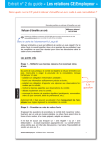
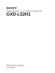
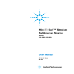
Variable Leak Valve
Model
951-5106
User Manual
87-400-085-01 (D)
05/2011
Notices
© Agilent Technologies, Inc. 2011
No part of this manual may be
reproduced in any form or by any
means (including electronic storage
and retrieval or translation into a
foreign language) without prior
agreement and written consent from
Agilent Technologies, Inc. as governed
by United States and international
copyright laws.
Manual Part Number
Publication Number: 87-400-085-01 (D)
Edition
Edition 05/2011
Printed in ITALY
Agilent Technologies Italia S.p.A.
Vacuum Products Division
Warranty
The material contained in this
document is provided “as is,” and is
subject to being changed, without
notice, in future editions. Further, to
the maximum extent permitted by
applicable law, Agilent disclaims all
warranties, either express or implied,
with regard to this manual and any
information contained herein,
including but not limited to the
implied warranties of merchantability
and fitness for a particular purpose.
Agilent shall not be liable for errors
or for incidental or consequential
damages in connection with the
furnishing, use, or performance of
this document or of any information
contained herein. Should Agilent and
the user have a separate written
agreement with warranty terms
covering the material in this
document that conflict with these
terms, the warranty terms in the
separate agreement shall control.
Via F.lli Varian, 54
10040 Leinì (TO)
ITALY
Technology Licenses
The hardware and/or software
described in this document are
furnished under a license and may be
used or copied only in accordance
with the terms of such license.
Restricted Rights Legend
If software is for use in the
performance of a U.S. Government
prime contract or subcontract,
Software is delivered and licensed as
“Commercial computer software” as
defined in DFAR 252.227-7014 (June
1995), or as a “commercial item” as
defined in FAR 2.101(a) or as
“Restricted computer software” as
defined in FAR 52.227-19 (June 1987)
or any equivalent agency regulation or
contract clause. Use, duplication or
disclosure of Software is subject to
Agilent Technologies’ standard
commercial license terms, and nonDOD Departments and Agencies of the
U.S. Government will receive no
greater than Restricted Rights as
defined in FAR 52.227-19(c)(1-2) (June
1987). U.S. Government users will
receive no greater than Limited Rights
as defined in FAR 52.227-14 (June
1987) or DFAR 252.227-7015 (b)(2)
(November 1995), as applicable in any
technical data.
Trademarks
Windows and MS Windows are U.S.
registered trademarks of Microsoft
Corporation.
Safety Notices
CAUTION
A CAUTION notice denotes a hazard.
It calls attention to an operating
procedure, practice, or the like that, if
not correctly performed or adhered to,
could result in damage to the product
or loss of important data. Do not
proceed beyond a CAUTION notice
until the indicated conditions are fully
understood and met.
WARNING
A WARNING notice denotes a
hazard. It calls attention to an
operating procedure, practice, or the
like that, if not correctly performed
or adhered to, could result in
personal injury or death. Do not
proceed beyond a WARNING notice
until the indicated conditions are
fully understood and met.
Variable Leak Valve User Manual / 87-400-085-01 (D)
Variable Leak Valve
Variable Leak Valve
Variable Leak Valve User Manual / 87-400-085-01 (D)
3/36
Variable Leak Valve
4/36
Variable Leak Valve User Manual / 87-400-085-01 (D)
Contents
Contents
1
Instructions for Use 7
Safety Information 9
General
10
Variable Leak Valve Outline 13
Flange Connection 14
Inlet Gas Connection
14
Use 15
To Establish a New Stop Position16
To Set Stop Position at any Leak Rate
17
Operating at Low Leak Rates 17
Changes in Leak Rate with Variation in Room Temperature
18
Bakeout Procedure 18
To Use as a Roughing Valve 19
Adjustment of Handle Position
20
If Valve Will not Close Leak-Tight 21
Lubrication Instructions 24
Loss of Sensitivity at High Leak Rates
26
Replacement Parts 28
Accessories 30
Variable Leak Valve User Manual / 87-400-085-01 (D)
5/36
Contents
6/36
Variable Leak Valve User Manual / 87-400-085-01 (D)
Variable Leak Valve User Manual
1
Instructions for Use
Safety Information 9
General
10
Variable Leak Valve Description 11
The Valve is Shipped in a Closed, LeakTight Condition. 11
Variable Leak Valve Specifications
12
Variable Leak Valve Outline 13
Flange Connection 14
Inlet Gas Connection 14
Use 15
To Establish a New Stop Position 16
To Set Stop Position at any Leak Rate 17
Operating at Low Leak Rates 17
Changes in Leak Rate with Variation in Room
Temperature
18
Bakeout Procedure 18
Bakeout in Open Position
18
Bakeout in Closed Position 19
Operation After Bakeout 19
To Use as a Roughing Valve 19
Adjustment of Handle Position 20
Original Instructions
7/36
1
Instructions for Use
If Valve Will not Close Leak-Tight 21
Disassemble 21
Inspect and Clean Sapphire 22
Inspect and Clean Valve Body 22
Inspect and Clean Gasket Assembly 23
Re-Install Sapphire Assembly 23
Re-Install Gasket Assembly 24
Leak-Check and Adjust Closure 24
Lubrication Instructions 24
Loss of Sensitivity at High Leak Rates 26
Disposal 27
Replacement Parts 28
Accessories
30
8/36
Variable Leak Valve User Manual / 87-400-085-01 (D)
1
Instructions for Use
Safety Information
Safety Information
This equipment is destined for use by professionals. The user should
read this instruction manual and any other additional information
supplied by Agilent before operating the equipment. Agilent will not
be held responsible for any events occurring due to non-compliance,
even partial, with these instructions, improper use by untrained
persons, non-authorized interference with the equipment or any
action contrary to that provided for by specific national standards.
This manual uses the following standard protocol:
CAUTION!
The caution messages are displayed before procedures which, if not followed,
could cause damage to the equipment.
WARNING!
The warning messages are for attracting the attention of the operator to a
particular procedure or practice which, if not followed correctly, could lead
to serious injury.
NOTE
The notes contain important information taken from the text.
Variable Leak Valve User Manual / 87-400-085-01 (D)
9/36
1
Instructions for Use
General
General
The variable leak valve can be added to any vacuum system to
establish an adjustable leak. It offers unprecedented control
sensitivity and stability with leak rates as small as 1 x 10⁻¹⁰ Torr-litres
per second. Leak rate adjustment is controlled with knurled knobs.
The entire valve, including the drive mechanism, is bakeable to 450°C
in either the open or closed position. Both components of the seal
mechanism (sapphire assembly and gasket assembly) are easily
replaceable.
Figure 1
10/36
Variable leak valve
Variable Leak Valve User Manual / 87-400-085-01 (D)
1
Instructions for Use
General
Variable Leak Valve Description
The variable leak valve includes a movable piston with an opticallyflat sapphire that meets a captured metal gasket (see the following
figure). This forms a seal completely free from friction, seizing, and
shear. The sapphire’s movement is controlled through a threaded
shaft-and-lever mechanism having a mechanical advantage of 13,000
to 1. Spring washers keep this drive mechanism constantly loaded
and eliminate the backlash usually associated with this type of
device. This provides immediate response to small movements in the
finger-controlled adjusting knobs. While some permanent
compression takes place in the gasket each time a seal is made, the
change is very slight. Return of the knob to a previous position will
result in approximately the same leak rate.
The Valve is Shipped in a Closed, Leak-Tight
Condition.
To open a leak, the knurled knobs must be turned (together) a
minimum of two full turns counterclockwise. The valve is closed by
turning the knobs (together) clockwise to the stop position against
the handle.
Figure 2
Sealing detail
Variable Leak Valve User Manual / 87-400-085-01 (D)
11/36
1
Instructions for Use
General
Variable Leak Valve Specifications
Tab. 1
Minimum leak rate
Rate of change of
leak
Vacuum range
Temperature range
Inlet gas pressure
Gasket life
Material
Weight
12/36
1 x 10⁻⁹ Torr-litres/sec. in normal operation;
1 x 10⁻¹⁰ Torr-litres/sec. with condensable vapours
eliminated from leak gas
The valve provides an increasing rate of change as
the size of the leak increases giving precise control
in proportion to the size of the leak
From atmospheric pressure to below 10-11 Torr
Up to 450 C in either open or closed position
500 psi maximum
For unbaked systems, approximately 300
closures;
For baked systems, 20 to 30 closures
Gasket assemblies are replaceable
300 series stainless steel; sapphire; OFHC copper
and copper alloy
1.8 Kg (4 lbs)
Variable Leak Valve User Manual / 87-400-085-01 (D)
1
Instructions for Use
Variable Leak Valve Outline
Variable Leak Valve Outline
The outline dimensions for the variable leak valve are shown in the
following figure.
Figure 3
Variable leak valve outline
Variable Leak Valve User Manual / 87-400-085-01 (D)
13/36
1
Instructions for Use
Flange Connection
Flange Connection
The valve is shipped in a closed, leak-tight position, lubricated and
ready for installation.
The ConFlat flange on which the variable leak valve is mounted
mates with any 2 /4 inch O.D. ConFlat flange.
1.
Place a new copper gasket (Agilent part no. 953-5014) between
the two ConFlat flanges.
2.
Lubricate and install bolts and nuts.
Use Fel-Pro C-100 high temperature lubricant on screw threads
and under the nuts.
3.
Tighten each nut 180° apart in sequence to 5 to 8 ft-lbs torque.
This will partially close the gap between the flange faces. Repeat
the sequential tightening two more cycles.
4.
The copper gaskets are partially sheared in making the seal and
the bolts should be tightened until the flange faces meet.
5.
Leak-check the connection.
Inlet Gas Connection
The connection is made through standard Mini-Con- Flat flanges.
A Mini-ConFlat flange-to-flare-fitting adapter kit (Agilent part
no. 951-5117) is provided as an option.
14/36
1.
Place a new copper gasket (Agilent part no. 953-5014) between
the two ConFlat flanges.
2.
Lubricate and install bolts and nuts.
Use Fel-Pro C-100 high temperature lubricant on screw threads
and under the nuts.
3.
Tighten each nut 180 ° apart in sequence to 5 to 8 ft-lbs torque.
This will partially close the gap between the flange faces. Repeat
the sequential tightening two more cycles.
4.
The copper gaskets are partially sheared in making the seal and
the bolts should be tightened until the flange faces meet.
5.
Leak-check the connection.
Variable Leak Valve User Manual / 87-400-085-01 (D)
Instructions for Use
Use
1
Use
WARNING!
The main danger of explosion in vacuum equipment occurs during
backfilling from pressurized gas cylinders.
Explosions cause flying debris which may cause serious personal injury or death
and destroy equipment.
The following precautions must be exercised when admitting gas into
a vacuum system:
CAUTION!
1.
Check that the leak valve is in the closed position before
admitting gas into the backfill line.
2.
Always use a pressurized relief valve in the backfill line.
Never operate the valve without knowing the relationship of the stop position to
the point of leak tight closure. The point at which the valve closes cannot be
felt by the operator and severe overdriving may fracture the sapphire.
Figure 4
Knob adjustment
Variable Leak Valve User Manual / 87-400-085-01 (D)
15/36
1
Instructions for Use
To Establish a New Stop Position
The valve is received in a closed, leak-tight position. The adjusting
knurled knobs are tightened against the handle.
During normal operation, the knobs are locked together with respect
to the fine-drive screw. To open a leak, turn both knobs together a
minimum of two full turns counterclockwise. To close a leak, turn the
knobs together until the collar botts against the handle (the stop
position has been reached).
To Establish a New Stop Position
Each time a seal is made, the valve's captured metal gasket is
compressed. High temperature bakeout accelerates the compression
of the gasket. If no change is made to the position of the knobs on the
fine-drive screw, the point of closure will gradually come closer to
the point at which the knobs and collar butt against the handle.
Eventually the stop will be engaged before a leak-tight closure is
made. When this happens, a new stop position must be established.
16/36
1.
The valve must be attached to a leak detector or the system must
be equipped with gauging adequate to determine when no leak
exists.
2.
With the knobs tightened against the handle, unlock the knobs
from each other by holding the inner knob and turning the outer
knob counterclockwise about four turns.
3.
Turn the inner knob counterclockwise until it is locked tight
against the outer knob.
4.
Turn the two locked knobs clockwise until the valve closes as
indicated on the leak detector or system gauging.
5.
Turn the knobs clockwise two additional turns past the point of
closure.
6.
Loosen the knobs from each other without allowing the screw to
turn. Turn the inner knob clockwise until the collar is against the
handle, then turn the outer knob clockwise until it locks against
the inner knob. The knobs are now in position to return to and
stop at a point two turns past closure.
7.
After the stop has been adjusted several times, the handle must
be reset as described in para. "Maintenance".
Variable Leak Valve User Manual / 87-400-085-01 (D)
1
Instructions for Use
To Set Stop Position at any Leak Rate
To Set Stop Position at any Leak Rate
The stop position can be adjusted to provide any desired leak rate.
NOTE
1.
Open the valve to the desired leak rate as determined by a leak
detector, vacuum gauge, or other experimental means.
2.
Loosen the knobs from each other without allowing the fine-drive
screw to turn.
3.
Turn the inner knob clockwise until the collar stops against the
handle. Turn the outer knob clockwise until it locks against the
inner knob.
4.
The valve can now be opened to larger leak rates and when
returned to the stop position will provide a leak of this pre-set
rate.
The valve cannot be closed leak-tight with the stop set in this manner. To close
the valve, follow the procedure outlined in the preceding paragraph.
Operating at Low Leak Rates
When the valve operates with leak rates of 1 x 10⁻⁹
Torr-litres/sec and smaller, condensable vapours and contaminants
reduce the leak opening. The valve must be baked to 250° in the open
position and under vacuum for 30 minutes to drive off these
internally adsorbed vapours. See the paragraph "Bakeout procedure".
For operation at leak rates of 3 x 10⁻¹⁰ Torr-litres/sec and lower, in
addition to the bakeout described above, the inlet gas must be free of
condensable vapours. Use a dry gas or pass the inlet gas through a
drying agent such as a liquid nitrogen cold trap. A molecular sieve
trap can be used for drying the gas but a filter must be employed to
assure that no particles of sieve enter the valve.
Variable Leak Valve User Manual / 87-400-085-01 (D)
17/36
1
Instructions for Use
Changes in Leak Rate with Variation in Room Temperature
Changes in Leak Rate with Variation in Room
Temperature
Changes in room temperature will cause changes in leak rate - as the
temperature rises, the leak rate increases. A leak setting should be
made in the range of interest and then mild heat applied to raise the
temperature of the valve to the maximum expected value. If the
resulting change in leak rate is not acceptable to the intended
experiment, some means of temperature control should be used.
Bakeout Procedure
Bakeout in Open Position
18/36
a
No special steps are required to bake the leak valve in the open
position.
b
A leak that has been set with the valve at room temperature will
increase due to thermal expansion as the valve is heated during
bakeout. Monitoring of system pressure and readjustment of the
leak is necessary if a constant leak is desired during temperature
cycling.
Variable Leak Valve User Manual / 87-400-085-01 (D)
1
Instructions for Use
To Use as a Roughing Valve
Bakeout in Closed Position
a
The valve must be overdriven three turns past closure (normal
setting is two turns) to compensate for differential expansion of
materials during bakeout.
b
To prepare the valve for bakeout, follow the procedure described
in paragraph “To establisha new stop position” with the following
exceptions: in steps 5 and 6, substitute "three turns" for the "two
turns" specified.
Operation After Bakeout
CAUTION!
a
Bakeout in the closed position to 250 °C and above will increase
the size of leak for a given setting of the knobs. A full three turns
may not be required to open a leak after bakeout. Length of
bakeout and elapsed time at temperature will both affect the
amount of change.
b
If the stops are to be readjusted, follow the procedure described
in steps "a" and "b" above.
After each bakeout cycle, before openiag or closing the valve, tighten the outer
knob against the inner one and lubricate the threads of the fine drive screw
with Fel-Pro C-100. After every three bakeouts over 300°C, disassemble and
lubricate the drive mechanism as described in the following para. “Lubrication
instructions”.
To Use as a Roughing Valve
The variable leak valve can be used as a roughing valve when
pumping small vacuum systems (some litres volume). The valve must
be opened to its maximum conductance for this operation.
Connect a roughing pump to the inlet gas fitting. Where available,
install a molecular sieve or liquid nitrogen trap in the line between
the pump and valve to reduce contamination from mechanical pump
oil vapours.
Variable Leak Valve User Manual / 87-400-085-01 (D)
19/36
1
Instructions for Use
Adjustment of Handle Position
Adjustment of Handle Position
As described previously, continual reduction in gasket height
necessitates resetting of the stop position and eventual readjustment
of handle position. When the angle between the handle and body at
point of closure has changed from its original parallel (approximate)
position to an angle of +/-5°, the valve should be readjusted. This
adjustment will maintain a proper relationship between handle travel
and the size of the leak.
CAUTION!
20/36
1.
Set handle.
Turn the locked knobs counterclockwise until the valve handle is
approximately parallel to the side of the valve body.
2.
Close valve using roughing screw as follows.
a
Carefully remove the hole cover from the top of the valve.
Do not exceed 8 ft.-lbs. or torque or the sapphire may be fractured.
b
With a 5/16” Allen wrench, tighten the roughing screw to 6 ft.-lbs.
of torque.
c
Replace the hole cover.
d
The valve should now be leak-tight, but this can be determined
reliably only with a leak detector. If the valve leaks across the
seal, refer to the following paragraph.
e
Adjust knobs as follows.
f
Turn the knobs together counterclockwise until a leak is
generated.
g
Turn the knobs clockwise until the valve is closed leak-tight.
h
Turn the knobs two additional turns clockwise to provide the
proper amount of overdrive.
i
Loosen the knobs without allowing the fine-drive screw to turn
then turn the inner knob clockwise until the collar is against the
handle. Lock the outer knob against the inner one.
j
Two counterclockwise turns of both knobs together should open
a leak.
Variable Leak Valve User Manual / 87-400-085-01 (D)
1
Instructions for Use
If Valve Will not Close Leak-Tight
If Valve Will not Close Leak-Tight
If the valve is not leak-tight across the sapphire-gasket seal after the
knobs have been turned to the stop position, one of several problems
may be the cause.
1.
The gasket has been compressed and the stops must be reset.
2.
The valve, sapphire, and/or gasket are contaminated and need
cleaning.
3.
The gasket is scratched, nicked, or compressed beyond further
use and must be replaced.
4.
The sapphire is fractured and must be replaced.
The following procedures should be followed in the order listed.
a
Follow the steps outlined in para. “To establish a new stop
position”.
If the valve is still not leak tight, proceed to step "b" below.
b
Disassemble, clean, and inspect the sealing components.
Particles, oxide on the gasket, or other contaminants may
prevent the valve from closing leak-tight. Disconnect the valve
from other components and disassemble. Inspect and clean the
valve, sapphire, and gasket as described in the following steps.
Disassemble
Refer to the figure “Variable leak valve assembly drawing”.
a
Turn both knobs counterclockwise four turns.
b
Carefully remove the pressed-in hole cover (11) and with a 5/16”
Allen wrench loosen the roughing screw two turns.
c
Use a clean 1/4" Allen wrench to remove the gasket assembly (1).
The thread is normal right hand and 20-25 ft.-lbs. of torque will
be required to loosen it.
d
Clean the sapphire removal tool with acetone, insert it into the
hole that held the gasket assembly, and engage the fingers of the
tool with the slots on the periphery of the sapphire assembly.
Variable Leak Valve User Manual / 87-400-085-01 (D)
21/36
1
Instructions for Use
If Valve Will not Close Leak-Tight
e
Turn the valve and tool upside down and turn the tool
counterclockwise to remove the sapphire assembly. Four full
turns will disengage the threads.
f
Maintain the upside down position of valve and tool, and lower
the tool and sapphire assembly from the valve.
Inspect and Clean Sapphire
a
Check the sapphire to be sure that it has no cracks or chips. Any
fractures will require replacement of the sapphire assembly.
b
Check the cleanliness of the polished face by viewing light
reflected from its surface. Flush the face with acetone (CP grade
recommended) and wipe off any film or grease.
Be sure that no particles remain on the sapphire when ready for
re-assembly.
Inspect and Clean Valve Body
22/36
a
Check the valve body for any loose particles of other
contaminants.
b
Remove any contaminants by flushing acetone through the inlet
gas fitting while holding the valve upright.
c
Blow out the valve with a clean, dry gas through the inlet gas
fitting.
Variable Leak Valve User Manual / 87-400-085-01 (D)
1
Instructions for Use
If Valve Will not Close Leak-Tight
CAUTION!
Do not use compressed air to blow out the valve. The possible high content of
particles, water vapour, and oil will contaminate the valve. Re-cleaning and
possible gasket replacement may then be required.
Inspect and Clean Gasket Assembly
a
Inspect the copper alloy gasket to be sure that it is clean, smooth,
free of oxide, and protrudes above the surface of the gasket collar
by at least 0.002 inch. A hand lens or microscope will facilitate
inspection of the surface.
b
If the top surface of the gasket is scored, scratched, or nicked, the
gasket assembly must be replaced.
c
If the copper portion of the assembly does not protrude at least
0.002 inch above the collar, the gasket assembly must be
replaced.
d
Oily films or other residue should be removed using acetone.
e
Oxide or other slight surface imperfections can generally be
removed by polishing with a very fine rouge paper. When
polishing, rotate the gasket assembly about its centre axis to
avoid leaving scratches that cross the sealing surface. Clean the
gasket with acetone after polishing.
f
Keep the gasket free of contamination while awaiting reassembly.
Re-Install Sapphire Assembly
a
Hold the sapphire removal tool upright and attach the sapphire
assembly to the tool engaging the four slots. Be certain that the
tool is clean.
b
With the valve in the upside down position, carefully insert the
tool and sapphire into the valve. Turn the tool clockwise to
engage the threads. Only light finger pressure is required to
tighten the assembly into the valve properly.
Variable Leak Valve User Manual / 87-400-085-01 (D)
23/36
1
Instructions for Use
Lubrication Instructions
CAUTION!
Do not overtighten the sapphire assembly with the removal tool.
Heavy tightening can cause the tool to raise a burr in the slots of the sapphire
assembly. These burrs can prevent subsequent removal of the sapphire
assembly from the valve.
Re-Install Gasket Assembly
NOTE
a
To avoid contamination, hold the valve in the upright position.
Install the gasket assembly and tighten finger-tight.
b
Tighten the gasket assembly to 22 to 24 ft.-lbs. of torque. Check
that the Allen wrench is clean before use.
Install the valve on the vacuum system as soon as possible after re-assembly to
avoid particle contamination. If storage is necessary, place valve in a clean
polyethylene bag and close the bag securely. Avoid setting the valve on dusty
surfaces.
Leak-Check and Adjust Closure
Reset the handle position, roughing screw and knobs,
and leak-check the valve as described in para. “Adjustment of handle
position”.
Lubrication Instructions
Fel-Pro C-100 is recommended for lubrication. After each bakeout
cycle, lubricate the threads of the fine-drive screw. After every three
bakeouts at temperatures over 300°C, disassemble the drive
mechanism and lubricate it. Use the SST brush to remove flaky or
caked-on lubricant before re-lubrication.
Refer to the figure “Variable leak valve assembly drawing”.
24/36
Variable Leak Valve User Manual / 87-400-085-01 (D)
1
Instructions for Use
Lubrication Instructions
1.
Open the valve by turning both knobs four counterclockwise
turns.
2.
Withdraw the two Phillips head screws on the upper part of the
valve body and remove the cover.
3.
Remove the roughing screw (10). Lubricate its threads and the
spherical socket.
4.
Insert the two Phillips head screws that held the cover into the
two pivot rods and, using the screws as handles, pull out the
rods.
5.
Lift out the handle. Its sides have been sprayed with a
semipermanent coat of molybdenum-disulphide. The lubricant in
most cases will not require replenishing. If the user judges that
re-lubrication is necessary, a small amount of Fel-Pro C-100
should be applied to each side of the handle where it guides in
the body.
6.
Remove the rod assembly and lubricate both ends. Replace it.
7.
Lubricate the pivot rod holes in the handle. Do not lubricate the
pivot rod holes in the body.
8.
Reassemble the handle and pivot rods.
9.
Replace the roughing screw, valve cover, and two small screws.
10. Follow the procedure specified in para. “Adjustment of handle
position” to close the valve and adjust the drive mechanism for
proper operation.
Variable Leak Valve User Manual / 87-400-085-01 (D)
25/36
1
Instructions for Use
Loss of Sensitivity at High Leak Rates
Loss of Sensitivity at High Leak Rates
Repeated bakeouts at 450°C will result in partial annealing and a loss
of tension in the spring washers that provide the force to open the
valve. This will be evidenced by decreasing sensitivity of control at
high leak rates. This is not a common situation, but may occur after
months of use under high-temperature conditions. Replacement of
the spring washers and adjustment are required.
26/36
1.
Disassemble drive mechanism.
a
Open the valve four counterclockwise turns of the knobs.
b
Withdraw the two Phillips head screws on the upper part of the
valve body and remove the cover.
c
Remove the roughing screw.
d
Remove the two pivot rods by grasping each with a screw. Lift
out the handle.
2.
Replace spring washers.
e
With a 3/4" hex-socket wrench, remove the nut above the spring
washers.
f
Remove and replace the spring washers.
g
Replace the 3/4" hex nut.
3.
Adjust tension.
h
With a /4" hex-socket-wrench, tighten the nut above the spring
washers just enough so that there is no clearance between the
washers and the nut.
4.
Reassemble.
i
Replace the handle, pivot rods, roughing screw, and cover.
j
Repeat the closure adjustment to reposition the handle and
knobs.
Variable Leak Valve User Manual / 87-400-085-01 (D)
1
Instructions for Use
Loss of Sensitivity at High Leak Rates
Disposal
Meaning of the "WEEE" logo found in labels
The following symbol is applied in accordance with the EC WEEE
(Waste Electrical and Electronic Equipment) Directive.
This symbol (valid only in countries of the European Community)
indicates that the product it applies to must NOT be disposed of
together with ordinary domestic or industrial waste but must be sent
to a differentiated waste collection system.
The end user is therefore invited to contact the supplier of the device,
whether the Parent Company or a retailer, to initiate the collection
and disposal process after checking the contractual terms and
conditions of sale.
Variable Leak Valve User Manual / 87-400-085-01 (D)
27/36
1
Instructions for Use
Replacement Parts
Replacement Parts
Figure 5
Variable leak valve assembly drawing
Please refer to the preceding figure
Tab. 2
28/36
Ref. item
Description
Q.ty req.d
Part Number
1*
Gasket assembly
1
953-5050
2*
Sapphire assembly
1
953-0072
6*
Spring washer
3
7
Nut
1
8
Rod assembly
1
9
Cover
1
10
Roughing screw
1
11
Hole cover
1
Variable Leak Valve User Manual / 87-400-085-01 (D)
1
Instructions for Use
Replacement Parts
Ref. item
Description
Q.ty req.d
12
Pivot rod
2
13
Pan head screw, 8-32 x 1/4 lg
2
14*
Handle
1
15*
Knob
2
16*
Fine drive screw assembly
1
17*
Fine drive spring washer
1
18*
Collar
1
---*
Sapphire removal tool
1
---*
5/16” Allen wrench
1
---*
1/4” Allen wrench
1
---*
SST brush
1
---*
High temperature lubricant
Fel-Pro C-100
1
Repair Kit
Part Number
SR0061417400
962-0014
* This item is part of Repair Kit 962-0014.
Variable Leak Valve User Manual / 87-400-085-01 (D)
29/36
1
Instructions for Use
Accessories
Accessories
Tab. 3
30/36
Description
Part Number
Mating ConFlat flange 2 ¾” -rotatable
F0275-0150-RCE
Mating ConFlat flange 2 ¾” –non-rotatable
F0275-0150-NCE
Copper gasket for 2 ¾” CFF – Pkg./10
FG-0275-CI
Screw and nuts for 2 ¾” CFF – Pkg./25
FB-0275-CI
Mating Mini-ConFlat flange 1 1/3” - rotatable
F0133-0075-RCEW
Mating Mini-ConFlat flange 1 1/3” – non-rotatable
F0133-0075-NCE
Copper gasket for 1 1/3” – pkg./10
FG-0133-CI
Screw and nuts for 1 1/3” – pkg./25
FB-0133-C
Flare fitting adapter kit
951-5117
Consists of:
Q.ty
x
Adapter flare – Mini-ConFlat
1
x
Mini flange screws 8-32”
6
x
Nut for mini flange 8-32”
6
x
Gasket for mini flange
10
x
Fitting nut (28629886-00)
1
x
Fitting sleeve (28629887-00)
1
Variable Leak Valve User Manual / 87-400-085-01 (D)
Request for Return Form
Sales and Service Offices
United States
Agilent Technologies
Vacuum Products Division
121 Hartwell Avenue
Lexington, MA 02421 - USA
Tel.: +1 781 861 7200
Fax: +1 781 860 5437
Toll-Free: +1 800 882 7426
India
Agilent Technologies India Pvt. Ltd.
Vacuum Product Division
G01. Prime corporate Park,
230/231, Sahar Road, Opp. Blue Dart Centre,
Andheri (East), Mumbai – 400 099.India
Tel: +91 22 30648287/8200
Fax: +91 22 30648250
Toll Free: 1800 113037
Italy
Agilent Technologies Italia S.p.A.
Vacuum Products Division
Via F.lli Varian 54
10040 Leini, (Torino) - Italy
Tel.: +39 011 997 9111 Fax: +39 011 997 9350
Toll-Free: 00 800 234 234 00
Southeast Asia
Agilent Technologies Sales Sdn Bhd
Vacuum Products Division
Unit 201, Level 2 uptown 2,
2 Jalan SS21/37, Damansara Uptown
47400 Petaling Jaya,
Selangor, Malaysia
Tel : +603 7712 6106
Fax: +603 6733 8121
Taiwan
Agilent Technologies Taiwan Limited
Vacuum Products Division (3F)
20 Kao-Shuang Rd.,
Pin-Chen City, 324
Taoyuan Hsien , Taiwan, R.O.C.
Tel. +886 34959281
Toll Free: 0800 051 342
Canada
Central coordination through: Agilent Technologies
Vacuum Products Division
121 Hartwell Avenue
Lexington, MA 02421 - USA
Tel.: +1 781 861 7200
Fax: +1 781 860 5437
Toll-Free: +1 800 882 7426
Japan
Agilent Technologies Japan, Ltd.
Vacuum Products Division
8th Floor Sumitomo Shibaura Building
4-16-36 Shibaura Minato-ku Tokyo 108-0023 - Japan
Tel.: +81 3 5232 1253
Fax: +81 3 5232 1710
Toll-Free: 0120 655 040
UK and Ireland
Agilent Technologies UK, Ltd.
Vacuum Products Division
6 Mead Road Oxford Industrial Park
Yarnton, Oxford OX5 1QU – UK
Tel.: +44 (0) 1865 291570
Fax: +44 (0) 1865 291571
Toll free: 00 800 234 234 00
China
Agilent Technologies (China) Co. Ltd
Vacuum Products Division
No.3, Wang Jing Bei Lu,
Chao Yang District,
Beijing, 100102
China
Tel.: +86 (10) 6439 7718
Toll-Free: 800 820 6556
France
Agilent Technologies France
Vacuum Products Division
7 Avenue des Tropiques
Z.A. de Courtaboeuf - B.P. 12
91941 Les Ulis cedex - France
Tel.: +33 (0) 1 69 86 38 84
Fax: +33 (0) 1 69 86 29 88
Toll free: 00 800 234 234 00
Germany and Austria
Agilent Technologies
Vacuum Products Division Alsfelder Strasse 6 Postfach 11
14 35
64289 Darmstadt – Germany
Tel.: +49 (0) 6151 703 353
Fax: +49 (0) 6151 703 302
Toll free: 00 800 234 234 00
Korea
Agilent Technologies Korea, Ltd.
Vacuum Products Division
Shinsa 2nd Bldg. 2F 966-5 Daechi-dong
Kangnam-gu, Seoul
Korea 135-280
Tel.: +82 2 3452 2452
Fax: +82 2 3452 2451
Toll-Free: 080 222 2452
Mexico
Agilent Technologies
Vacuum Products Division
Concepcion Beistegui No 109 Col Del Valle
C.P. 03100 – Mexico, D.F.
Tel.: +52 5 523 9465
Fax: +52 5 523 9472
Other Countries
Agilent Technologies Italia S.p.A.
Vacuum Products Division
Via F.lli Varian 54 10040 Leini, (Torino) Italy
Tel.: +39 011 997 9111
Fax: +39 011 997 9350
Toll-Free: 00 800 234 234 00
Benelux
Agilent Technologies Netherlands B.V.
Vacuum Products Division
Herculesweg 8
4338 PL Middelburg
The Netherlands
Tel.: +31 118 671570
Fax: +31 118 671569
Toll-Free: 00 800 234 234 00
Singapore
Agilent Technologies Singapore Pte. Ltd,
Vacuum Products Division
Agilent Technologies Building,
1 Yishun Avenue 7,
Singapore 768923
Tel : (65) 6215 8045
Fax : (65) 6754 0574
© Agilent Technologies, Inc. 2011
Printed in ITALY
05/2011
Publication Number: 87-400-085-01 (D)
Customer Support & Service
NORTH AMERICA:
Toll Free: 800 882 7426, Option 3
[email protected]
EUROPE:
Toll Free: 00 800 234 234 00
[email protected]
PACIFIC RIM:
please visit our website for individual office
information http://www.agilent.com
Worldwide Web Site, Catalog and Order
On-line:
www.agilent.com
Representative in most countries
12/10