1
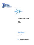
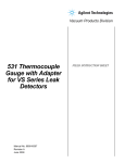
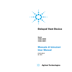
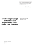
Turbo-V Vent Device Model 969-9831 969-9731 User Manual 87-900-806-01 (I) 05/2012 Notices © Agilent Technologies, Inc. 2011 No part of this manual may be reproduced in any form or by any means (including electronic storage and retrieval or translation into a foreign language) without prior agreement and written consent from Agilent Technologies, Inc. as governed by United States and international copyright laws. Manual Part Number Publication Number: 87-900-806-01 (I) Edition Edition 05/2012 Printed in ITALY Agilent Technologies Italia S.p.A. Vacuum Products Division Via F.lli Varian, 54 10040 Leinì (TO) ITALY Warranty The material contained in this document is provided “as is,” and is subject to being changed, without notice, in future editions. Further, to the maximum extent permitted by applicable law, Agilent disclaims all warranties, either express or implied, with regard to this manual and any information contained herein, including but not limited to the implied warranties of merchantability and fitness for a particular purpose. Agilent shall not be liable for errors or for incidental or consequential damages in connection with the furnishing, use, or performance of this document or of any information contained herein. Should Agilent and the user have a separate written agreement with warranty terms covering the material in this document that conflict with these terms, the warranty terms in the separate agreement shall control. Technology Licenses The hardware and/or software described in this document are furnished under a license and may be used or copied only in accordance with the terms of such license. Restricted Rights Legend If software is for use in the performance of a U.S. Government prime contract or subcontract, Software is delivered and licensed as “Commercial computer software” as defined in DFAR 252.227-7014 (June 1995), or as a “commercial item” as defined in FAR 2.101(a) or as “Restricted computer software” as defined in FAR 52.227-19 (June 1987) or any equivalent agency regulation or contract clause. Use, duplication or disclosure of Software is subject to Agilent Technologies’ standard commercial license terms, and nonDOD Departments and Agencies of the U.S. Government will receive no greater than Restricted Rights as defined in FAR 52.227-19(c)(1-2) (June 1987). U.S. Government users will receive no greater than Limited Rights as defined in FAR 52.227-14 (June 1987) or DFAR 252.227-7015 (b)(2) (November 1995), as applicable in any technical data. Trademarks Windows and MS Windows are U.S. registered trademarks of Microsoft Corporation. Safety Notices CAUTION A CAUTION notice denotes a hazard. It calls attention to an operating procedure, practice, or the like that, if not correctly performed or adhered to, could result in damage to the product or loss of important data. Do not proceed beyond a CAUTION notice until the indicated conditions are fully understood and met. WARNING A WARNING notice denotes a hazard. It calls attention to an operating procedure, practice, or the like that, if not correctly performed or adhered to, could result in personal injury or death. Do not proceed beyond a WARNING notice until the indicated conditions are fully understood and met. Turbo-V Vent Device User Manual / 87-900-806-01 (I) Turbo-V Vent Device Turbo-V Vent Device Turbo-V Vent Device / 87-900-806-01 (I) User Manual 3/34 Turbo-V Vent Device 4/34 Turbo-V Vent Device User Manual / 87-900-806-01 (I) Contents Contents 1 Instructions for Use 7 General Information 8 Turbo-V Vent Device Description 9 Disposal 2 10 Technical Information General 11 12 Vent Control Unit 13 Vent Valve 14 Vent Device Specifications 15 Turbo-V Vent Device Outline 17 Control Unit Installation 18 Vent Valve Installation 19 Operation 20 Time Setting 21 Battery Replacement 25 Turbo-V Vent Device Replacement Parts 28 Turbo-V Vent Device / 87-900-806-01 (I) User Manual 5/34 Contents 6/34 Turbo-V Vent Device User Manual / 87-900-806-01 (I) Turbo-V Vent Device User Manual 1 Instructions for Use General Information 8 Turbo-V Vent Device Description Disposal 10 9 7/34 1 Instructions for Use General Information General Information Operators and service personnel must be aware of all hazards associated with this equipment. They must know how to recognize hazardous and potentially hazardous conditions, and know how to avoid them. The consequences of unskilled, improper, or careless operation of the equipment can be serious. This product must only be operated and maintained by trained personnel. Every operator or service person must read and thoroughly understand operation/ maintenance manuals and any additional information provided by Agilent. All warnings and cautions should be read carefully and strictly observed. Address any safety, operation, and/or maintenance questions to your nearest Agilent office. The following format is used in this manual to call attention to hazards: WARNING! Warning are used when failure to observe instructions or precautions could result in injury or death. CAUTION! Warning Cautions are used when failure to observe instructions could result in damage to equipment, whether Agilent supplied or other associated equipment. NOTE 8/34 Information to aid the operator in obtaining the best performance from the equipment. Turbo-V Vent Device User Manual / 87-900-806-01 (I) Instructions for Use Turbo-V Vent Device Description Turbo-V Vent Device Description The Turbo-V vent device, consisting of a vent control unit and a vent valve, is a complete unit suitable for automatic venting of the Turbo-V pump when it is switched off or during a power failure switch (refer to the following figure). The Vent device is powered by the Turbo-V controller and a battery back-up capability is built in. The vent control unit is provided with a delay time to avoid undesired venting during a temporary power failure and to allow closure of the system valves before venting. A second setting is also provided to control the venting time to atmosphere. The Turbo-V pump must be vented when it is shut down to prevent the forepump oil from contaminating the Turbo-V and the connected chamber. Figure 1 Vent Valve and Control Unit The 969-9831, 969-9731 Turbo-V vent device consist of: a Vent Control Unit a Vent Valve Turbo-V Vent Device / 87-900-806-01 (I) User Manual 9/34 1 Instructions for Use Disposal Disposal Meaning of the "WEEE" logo found in labels The following symbol is applied in accordance with the EC WEEE (Waste Electrical and Electronic Equipment) Directive. This symbol (valid only in countries of the European Community) indicates that the product it applies to must NOT be disposed of together with ordinary domestic or industrial waste but must be sent to a differentiated waste collection system. The end user is therefore invited to contact the supplier of the device, whether the Parent Company or a retailer, to initiate the collection and disposal process after checking the contractual terms and conditions of sale. 10/34 Turbo-V Vent Device User Manual / 87-900-806-01 (I) 2 Technical Information General 12 Vent Control Unit 13 Vent Valve 14 Vent Device Specifications 15 Control Unit 15 Vent Valve 16 Turbo-V Vent Device Outline 17 Control Unit Installation 18 Vent Valve Installation 19 Operation 20 Time Setting 21 Battery Replacement 25 Turbo-V Vent Device Replacement Parts 28 11/34 2 Technical Information General General The 969-9831, 969-9731 Turbo-V vent device, consisting of a vent control unit and a vent valve, are a complete unit suitable for automatic venting of the Turbo-V pump when it is switched off or during a power failure switch (refer to the following figure). Figure 2 Vent Valve and Control Unit The 969-9831, 969-9731 Turbo-V vent device consist of: 12/34 a Vent Control Unit a Vent Valve Turbo-V Vent Device User Manual / 87-900-806-01 (I) 2 Technical Information General Vent Control Unit The vent control unit is mains powered via the IEC 60320 C14 plug placed on its front panel and a battery back-up capability is built in. The vent control unit is not suitable for rack mounting. Four taped holes in the bottom surface are available for fastening (see Figure 4 for details). When the supply voltage is present, the internal battery is automatically recharged, then the timer circuits are inhibited and reset. When the supply voltage is shut off, the valve still remains not energized and the delay timer counter starts. After the pre-set delay time, the valve opens and the venting time count starts. At the end of the venting time, the valve is de-energized and the battery is disconnected. The battery is protected against short circuits on the valve. Two blue LEDs indicate when the mains is supplied and when the valve is driven (Valve closed). Other three LEDs indicates the backup battery status. The red LED indicates that the battery actual charge level does not allow the actuation of the valve. It need to be charged before to be able to operate. In this condition, in case of power shutdown the Vent Valve opens immediately. The green LED indicates that battery actual charge level is ok; the yellow one indicates a charge level intermediate. NOTE If, even after a prolonged period of charging the green LED does not light, replace the internal battery. Turbo-V Vent Device 87-900-806-01 (I) User Manual 13/34 2 Technical Information General Vent Valve The vent valve consists of a small normally-closed straight through, electromagnetically-actuated and viton-sealed valve with an NW 10 KF flange on the high vacuum port and a filter or adapter tube 1/4” on the air entrance port. The valve opens under control of a metallic spring and closes when power is supplied to the valve electromagnet. NOTE 14/34 A riffled nozzle is provided for use in lieu of the sintered filter when the Turbo-V pump is vented by the dry gas bottle (line). Turbo-V Vent Device User Manual / 87-900-806-01 (I) 2 Technical Information Vent Device Specifications Vent Device Specifications Control Unit Table 1 Input: voltage 110-120 Vac ±10% (969-9831 model) 220-240 Vac ±10% (969-9731 model) frequency power fuses 50 to 60 Hz 15 VA 2 x T 315 mA 250V Output: voltage power (max) 24 Vdc able to drive a Turbo Pump Vent Valve 2.5 W Delay time Factory set to 16 seconds (adjustable up to 36 minutes) Venting time Factory set to 3 minutes (adjustable up to 36 minutes) Operating temperature 0 to 40 °C (32 °F to 104 °F) Storage temperature -20 °C to + 50 °C (-4 °F to +122 °F) Power cable With European or NEMA plug 3 meters long (optional) Valve cable 5 meters long Pollution degree 2 Max altitude 2000 m a.s.l. Compliance according to 61010-1 61326-1 (industrial level) Weight 2.5 kg (5.5 lbs) Turbo-V Vent Device 87-900-806-01 (I) User Manual 15/34 2 Technical Information Vent Device Specifications Vent Valve Table 2 16/34 High vacuum flange NW 10 KF Gas entrance Riffled nozzle 4.8 mm (0,19") O.D./Tube 1/4” Orifice size 1.2 mm (0.05") Pressure range 10-6 mbar to 1bar (10-7 Torr to atm) Leak rate 1x10⁻⁷ mbar l/s Life cycle One million cycles Input: voltage power 24 Vdc +10% -2% 2W Bakeout temperature 60 °C (140 °F) Mounting position Any Weight 120 g (0.27 Ibs) Turbo-V Vent Device User Manual / 87-900-806-01 (I) Technical Information Turbo-V Vent Device Outline 2 Turbo-V Vent Device Outline The outline dimensions for the Turbo-V Vent Device are shown in the following figure. 43. 49. Figure 3 24. Turbo-V Vent Device Outline Turbo-V Vent Device 87-900-806-01 (I) User Manual 17/34 2 Technical Information Control Unit Installation Control Unit Installation Place the control unit free standing on a stable surface or fasten it by means of the four suitable taped holes. Plug the power cable into a suitable power source. NOTE When first installed or after 6 months of non-use, leave the control unit under voltage for at least 3 hours in order to fully recharge the battery before use. Figure 4 18/34 Fastening holes (bottom view) Turbo-V Vent Device User Manual / 87-900-806-01 (I) 2 Technical Information Vent Valve Installation Vent Valve Installation Connect the NW 10 KF port to the chamber or pump vent port. This port is compatible with an NW 16 KF flange having an adaptive centering ring. NOTE Use the provided filter to prevent the ingress of dust, dirt or contaminants, when the pump is vented to atmosphere. CAUTION! When a dry gas bottle (line) is used, never exceed 1 bar (15 psig) to the riffled nozzle connection, otherwise a leak in the Turbo-V pump may occur. CAUTION! When a dry gas bottle line is used, check the correct venting time to prevent overpressuring the Turbo-V pump. NOTE The Turbo-V vent device has been designed to vent the Turbo-V pump only. To vent the chamber, it is advisable to install a suitable vent valve. Turbo-V Vent Device 87-900-806-01 (I) User Manual 19/34 2 Technical Information Operation Operation When the Turbo-V pump starts, the blue LED lights, indicating that the battery is being charged and the set timers are reset. If the pump is switched off or a power failure occurs, the LED goes off and the delay time starts. At the end of delay, the valve (blue) LED lights and the valve opens for the set time. At the end of the venting time the valve closes, the valve LED goes off, and the battery is switched off. If during the delay or venting time the Turbo-V pump is switched on (even if only for a few seconds) both delay and venting time are reset. NOTE CAUTION! 20/34 A charged battery is able to supply a minimum of 4 complete venting cycles with the maximum delay and venting time. The life of the battery is affected by ambient temperature. Never exceed the specified operating temperature and replace the battery every 30 months. Turbo-V Vent Device User Manual / 87-900-806-01 (I) 2 Technical Information Time Setting Time Setting WARNING! High voltage present in the control unit can cause severe injury or death. Service must be carried out only by qualified and authorized personnel. WARNING! The whole procedure described in this chapter must be carried out with the power cord detached from the unit. Turbo-V Vent Device 87-900-806-01 (I) User Manual 21/34 2 Technical Information Time Setting 1 Disconnect the power cord from the unit. 2 Remove the top cover of the Vent control unit by unscrewing the screws. Timers selectors Figure 5 3 22/34 Unit interior Choose the appropriate times, make the appropriate jumper settings and rotary switch position (refer to the following figure): place only one jumper for each timer to select the time unit between 1s, 8s and 64s; turn the rotary switch multiplier for the desired value between 0 to 9. Turbo-V Vent Device User Manual / 87-900-806-01 (I) 2 Technical Information Time Setting If the rotary switch is set to “0” the delay becomes zero (no delay) regardless of the jumper position. Exemple: to set a delay time of 40 seconds and a venting time of 4 minutes proceed as follows: CAUTION! Adjust the delay time rotary switch to 5 and place the jumper across 8s. Adjust the venting time rotary switch to 4 and place the jumper across 64s. Use the appropriate tool to adjust the time settings to avoid damages to the rotary switches. 4 Replace the cover by tightening all the screws. 5 Reconnect the power cord to the unit. Turbo-V Vent Device 87-900-806-01 (I) User Manual 23/34 2 Technical Information Time Setting The minimum venting times for each Turbo-V pump series with the high vacuum flange blanked off and leak tight, are listed below. NOTE Turbo-V 80 2/16 minute Turbo-V 300 4/16 minute Turbo-V 1000 0.5 minute The minimum venting time is the time needed to reach a pressure of about 500 mbar (375 Torr) inside the pump in order to avoid mechanical pump oil backstreaming and contamination of the Turbo-V pump. Vent Time Delay Time Figure 6 24/34 Timers setup selectors Turbo-V Vent Device User Manual / 87-900-806-01 (I) 2 Technical Information Battery Replacement Battery Replacement WARNING! High voltage present in the control unit can cause severe injury or death. Service must be carried out only by qualified and authorized personnel. WARNING! The whole procedure described in this chapter must be carried out with the power cord detached from the unit. 1 Disconnect the power cord from the unit. Remove the top cover of the Vent control unit by unscrewing the screws. Figure 7 Unit interior Turbo-V Vent Device 87-900-806-01 (I) User Manual 25/34 2 Technical Information Battery Replacement 2 Identify the battery positioned in the rear of the unit. 3 Disconnect both electrical connections. Figure 8 26/34 Internal Battery Turbo-V Vent Device User Manual / 87-900-806-01 (I) 2 Technical Information Battery Replacement 4 Slide the battery out sideways. Figure 9 5 WARNING! Battery removal Insert a new battery maintaining the electrical terminals towards the front of the unit. The new battery must be an Agilent Replacement Battery (see Orderable Parts Table). In order to be compliant with warranty rules it is mandatory using Agilent battery. 6 Reconnect the electrical connections according to the polarity (red wire “+”; black wire “-“). 7 Replace the cover by tightening all the screws. 8 Reconnect the power cord to the unit. Turbo-V Vent Device 87-900-806-01 (I) User Manual 27/34 2 Technical Information Turbo-V Vent Device Orderable Parts Turbo-V Vent Device Orderable Parts Table 3 Orderable Parts DESCRIPTION PART NUMBER Gas filter 28-900008-01 Battery 6 V 1Ah 74-103100-01 Mains cable NEMA plug 3m long 969-9958 Mains cable European plug 3m long 969-9957 For a complete overview of Agilent's extensive vacuum product line, please refer to the Vacuum Catalogue. 28/34 Turbo-V Vent Device User Manual / 87-900-806-01 (I) Request for Return Form Sales and Service Offices United States Agilent Technologies Vacuum Products Division 121 Hartwell Avenue Lexington, MA 02421 - USA Tel.: +1 781 861 7200 Fax: +1 781 860 5437 Toll-Free: +1 800 882 7426 India Agilent Technologies India Pvt. Ltd. Vacuum Products Division G01. Prime corporate Park, 230/231, Sahar Road, Opp. Blue Dart Centre, Andheri (East), Mumbai – 400 099.India Tel: +91 22 30648287/8200 Fax: +91 22 30648250 Toll Free: 1800 113037 Southeast Asia Agilent Technologies Sales Sdn Bhd Vacuum Products Division Unit 201, Level 2 uptown 2, 2 Jalan SS21/37, Damansara Uptown 47400 Petaling Jaya, Selangor, Malaysia Tel : +603 7712 6106 Fax: +603 6733 8121 Benelux Agilent Technologies Netherlands B.V. Vacuum Products Division Herculesweg 8 4338 PL Middelburg The Netherlands Tel.: +31 118 671570 Fax: +31 118 671569 Toll-Free: 00 800 234 234 00 Italy Agilent Technologies Italia S.p.A. Vacuum Products Division Via F.lli Varian 54 10040 Leini, (Torino) - Italy Tel.: +39 011 997 9111 Fax: +39 011 997 9350 Toll-Free: 00 800 234 234 00 Taiwan Agilent Technologies Taiwan Limited Vacuum Products Division (3F) 20 Kao-Shuang Rd., Pin-Chen City, 32450 Taoyuan Hsien , Taiwan, R.O.C. Tel. +886 34959281 Toll Free: 0800 051 342 Canada Central coordination through: Agilent Technologies Vacuum Products Division 121 Hartwell Avenue Lexington, MA 02421 - USA Tel.: +1 781 861 7200 Fax: +1 781 860 5437 Toll-Free: +1 800 882 7426 Japan Agilent Technologies Japan, Ltd. Vacuum Products Division 8th Floor Sumitomo Shibaura Building 4-16-36 Shibaura Minato-ku Tokyo 108-0023 - Japan Tel.: +81 3 5232 1253 Fax: +81 3 5232 1710 Toll-Free: 0120 655 040 UK and Ireland Agilent Technologies UK, Ltd. Vacuum Products Division 6 Mead Road Oxford Industrial Park Yarnton, Oxford OX5 1QU – UK Tel.: +44 (0) 1865 291570 Fax: +44 (0) 1865 291571 Toll free: 00 800 234 234 00 China Agilent Technologies (China) Co. Ltd Vacuum Products Division No.3, Wang Jing Bei Lu, Chao Yang District Beijing, 100102, China Tel: +86 (0)10 64397888 Fax: +86 (0)10 64391318 Toll free: 800 820 3278 Korea Agilent Technologies Korea, Ltd. Vacuum Products Division Shinsa 2nd Bldg. 2F 966-5 Daechi-dong Kangnam-gu, Seoul Korea 135-280 Tel: +82 (0)2 3452 2455 Fax: +82 (0)2 3452 3947 Toll free: 080 222 2452 Other Countries Agilent Technologies Italia S.p.A. Vacuum Products Division Via F.lli Varian 54 10040 Leini, (Torino) - Italy Tel.: +39 011 997 9111 Fax: +39 011 997 9350 Toll-Free: 00 800 234 234 00 France Agilent Technologies France Vacuum Products Division 7 Avenue des Tropiques Z.A. de Courtaboeuf - B.P. 12 91941 Les Ulis cedex - France Tel.: +33 (0) 1 69 86 38 84 Fax: +33 (0) 1 69 86 29 88 Toll free: 00 800 234 234 00 Mexico Agilent Technologies Vacuum Products Division Concepcion Beistegui No 109 Col Del Valle C.P. 03100 – Mexico, D.F. Tel.: +52 5 523 9465 Fax: +52 5 523 9472 Customer Support & Service Germany and Austria Agilent Technologies Sales & Services GmbH & Co. KG Vacuum Products Division Lyoner Str. 20 60 528 Frankfurt am Main GERMANY Tel: +49 69 6773 43 2230 Fax: +49 69 6773 43 2250 Singapore Agilent Technologies Singapore Pte. Ltd, Vacuum Products Division Agilent Technologies Building, 1 Yishun Avenue 7, Singapore 768923 Tel : (65) 6215 8045 Fax : (65) 6754 0574 © Agilent Technologies, Inc. 2012 Printed in ITALY 05/2012 Publication Number: 87-900-806-01 (I) NORTH AMERICA: Toll Free: 800 882 7426, Option 3 [email protected] EUROPE: Toll Free: 00 800 234 234 00 [email protected] PACIFIC RIM: please visit our website for individual office information http://www.agilent.com Worldwide Web Site, Catalog and Order On-line: www.agilent.com Representative in most countries 1/12