1
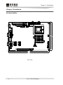
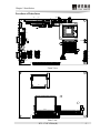
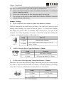
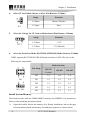
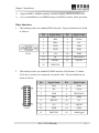
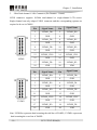
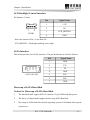
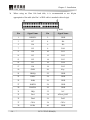
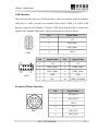
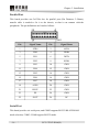
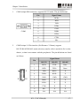
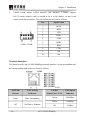
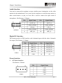
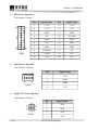
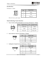
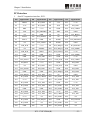
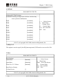
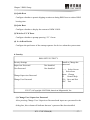
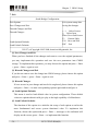
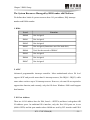
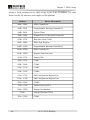
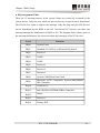
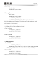
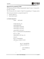
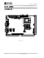
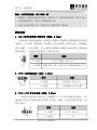
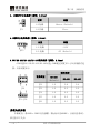
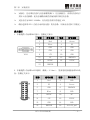
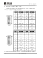
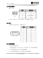
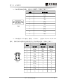
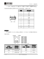
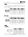
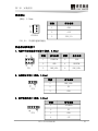
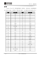
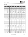
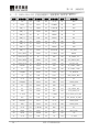
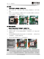
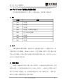
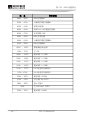
Chapter 2 Installation 1. COM1 adopts DB9 connector, supports RS232 mode. The pin definitions: COM1 2. Pin Signal Name 1 DCD# 2 RXD 3 TXD 4 DTR# 5 GND 6 DSR# 7 RTS# 8 CTS# 9 RI# COM2 adopts 2×5Pin interface (Pin Distance: 2.54mm), supports RS232/RS422/RS485 mode selection, transfer cable is needed to fix it to the chassis, so that it can connect with the peripherals. The pin definitions are listed as follows: Signal Name Pin COM2 RS232 RS422 RS485 1 DCD# TXD Data 2 RXD TXD+ Data+ 3 TXD RXD+ X 4 DTR# RXD X 5 GND GND GND 6 DSR# X X 7 RTS# X X 8 CTS# X X 9 RI# X X 10 NA NA NA EC51712CLDNA(B) 17