1
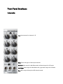
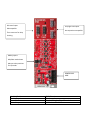
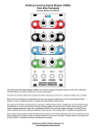
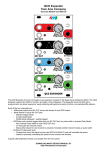
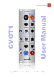
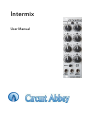
Intermix
User Manual
Intermix Description
Initially meant to be a mix expander for the G8 divider, it has morphed into a universal mix
expander. The Intermix has 8 attenuverting inputs that mix into one output. A gain switch changes
the output level of all three outputs to match the use: high gain for opening a filter, or lower gain
for setting pitch on a VCO.
The Intermix opens up many new possibilities for the G8. For example, it can be used as a
sequencer, or clock the G8 with a VCO and the Intermix becomes a waveform generator.
Multiple Intermixes can be chained together to produce multiple channels off of one G8. So you
can do things like
use one channel for pitch, a second channel for opening a filter, and a third for changing the
tempo of the oscillator clocking the G8.
There are 2 modes available. Both modes mix all 8 inputs into one output. The first mode has min
and max outputs. The second mode has separate outputs for the left and right bank of knobs. This
allows for two 4-output devices to be mixed separately.
"Universal" means the Intermix can tie other modules such as the Chaos Computer. All 8 analog
outputs of the Chaos Computer are available for mixing. In two channel mode the Intermix can
mix the X and Y outputs of the Chaos Computer separately. The intermix can also attach to other
modules such as the 4ms QPLFO. In fact, in two channel mode the Intermix could tie to two
QPLFOs.
Mode button selects the mode, and when held down selects trigger mode where all outputs are
triggers instead of gates. Reset input is edge sensitive i.e. resets on a rising edge. Trigger output
provides a trigger when the outputs change, useful in CV.
Front Panel Interface:
Intermix
1-8: Attenuverters for channels 1-8
Gain: Selects the gain of the output channels
Min/Left: Min output for Min/Max mode, left bank output for L/R mode
Max/Right: Max output for Min/Max mode, right bank output for L/R mode
Out: Main output. Always has all 8 channels mixed
8 channel inputs
G8 compatible
Left/right bank inputs
4ms expansion compatible
Thru connector for daisy
chaining
Mode jumpers
Min/Max mode shown
Move to other positions
for L/R mode
POWER GOES
HERE
Module Width
Module Depth
Power Connector
Power Requirements
8HP (40mm)
40mm
Standard Doepfer 10 pin Shrouded
± 12 Volts at 60mA Max