1
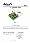
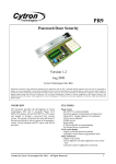
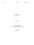
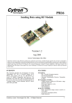
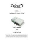
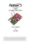
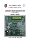
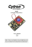
PR24
PID MOTOR CONTROLLER
Version 1.0
October 2009
Cytron Technologies Sdn. Bhd.
Information contained in this publication regarding device applications and the like is intended through suggestion only and may be superseded by
updates. It is your responsibility to ensure that your application meets with your specifications. No representation or warranty is given and no liability is
assumed by Cytron Technologies Incorporated with respect to the accuracy or use of such information or infringement of patents or other intellectual
property rights arising from such use or otherwise. Use of Cytron Technologies’s products as critical components in life support systems is not
authorized except with express written approval by Cytron Technologies. No licenses are conveyed, implicitly or otherwise, under any intellectual
property rights.
OVERVIEW
FEATURES
This document describes the development of Cytron
Technologies DIY (Do It Yourself) Project PR24. This
project describes the application of PID control
technique in motor position control. Schematic and
source code is provided. Please refer to Getting Start
section on running the PR24 with sample program.
PIC16F876A
- 8-bit microcontroller with 22 I/O
- operate with 5V supply
- operating speed 20MHz
LCD (2X16 characters)
-
2X16 characters display
- Operate at 5V
L293D Driver
-
600mA output current capability per channel
High noise immunity
DC Gear Motor SPG20-50K
-
Created by Cytron Technologies Sdn. Bhd. – All Rights Reserved
12V input voltage, 0.6W
Rated speed of 130rpm and rated torque of
58.8mN.m
60g of weight
1
ROBOT . HEAD to TOE
PR24 – PID Motor Controller
SYSTEM OVERVIEW
LCD DISPLAY
Set values
of, P, I, D
and ANGLE
DC
MOTOR
PIC 16F876A
Multi-turn
variable resistor
Feedback
GENERAL DESCRIPTION
PR24 is an open source microcontroller DIY kit. This
PIC microcontroller based project was designed for
user to understand the PID control technique. The
project uses the PID control technique to control the
motor position so that the motor can point to the angle
desired by user in the most stable manner. User can
physically indicate how the different values of P, I and
D can affect on the speed, steady state error stability
and overshoot during the transient response of the DC
motor. It also provides LCD (2x16 characters) for user
to indicate the values of P, I, D and angle which
selected by user.
PID Controller
PID (proportional-integral-derivative) controller is a
type of closed loop control mechanism which widely
used in industrial control system. Closed loop control
is used to correct the error of the output. Besides, this
technique can also improve both steady state errors,
minimize the overshoot and improve the transient
response.
PIC16F876A
This powerful (200 nanosecond instruction execution)
yet easy-to-program (only 35 single word instructions)
CMOS FLASH-based 8-bit microcontroller packs
Microchip's powerful PIC® architecture into an 28-pin
package and is upwards compatible with the
PIC16C5X, PIC12CXXX and PIC16C7X devices.
Feature of the device:
•
256 bytes of EEPROM data memory
• Self programming
•
ICD (In Circuit Debugging function)
•
2 Comparators
• 5 channels of 10-bit Analog-to-Digital (A/D)
converter
• 2 capture/compare/PWM functions
•
the synchronous serial port can be configured
as either 3-wire Serial Peripheral Interface
(SPI™) or the 2-wire Inter-Integrated Circuit
(I²C™) bus
• Universal Asynchronous Receiver
Transmitter (USART)
All of these features make it ideal for more advanced
level A/D applications in automotive, industrial,
appliances and consumer applications. Figure 3 shows
the pin diagram for PIC16F876A. For more
information about the PIC microcontroller, please refer
to the datasheet. The datasheet can be found in
microchip web site at: http://www.microchip.com
Figure 1
Error = set value – output value
Integral = Integral + error
Derivative = error – previous error
PWM = (P x error) + (I x Integral) + (D x Derivative)
Created by Cytron Technologies Sdn. Bhd. – All Rights Reserved
2
ROBOT . HEAD to TOE
PR24 – PID Motor Controller
Figure 3
L293D Driver
L293D is a monolithic integrated high voltage, high
current four channel driver designed to accept standard
DTL or TTL logic levels and drive inductive loads
(such as relays solenoids, DC and stepping motors) and
switching power transistors. Each pair of channels is
equipped with an enable input to simplify use as two
bridges. Internal clamp diodes are included. This
device is suitable for use in switching applications at
frequencies up to 5 kHz. In this project, L293D is
applied to control the speed of motor (ENABLE 1) and
also control the direction of the DC motor (INPUT 1
and INPUT 2). Figure4 shows the pin connection of
L293D.
Figure 5
For more information about the L293D, please refer to
the datasheet. The datasheet can be found at:
www.datasheetcatalog.com
Potentiometer
This multi-turn variable resistor is used in this project
for act as the feedback of motor position. Since this
multi-turn variable resistor can be turned 10 cycles,
therefore, the available angle in this project is 3600
degree.
Features:
• Special resistance tolerances to 1%
• Rear Shaft Extensions and Support Bearing
• Non turn lug
• Dual gang configuration and concentric shafts
• High torque and centre tap
• Special markings and front shaft extensions
• Servo unit available and slipping clutch
S
__
+
Figure 4
The L293D is assembled in a 16 lead plastic package
which has 4 center pins connected together and used
for heat sinking. The block diagram is shown:
Figure 6
Please refer to Getting Start section for cable
connection.
Created by Cytron Technologies Sdn. Bhd. – All Rights Reserved
3
ROBOT . HEAD to TOE
PR24 – PID Motor Controller
Figure 8 is a 2X16 character LCD. Figure 9 shows the
connection of LCD display. LCD connection pin and
function of each pin is shown:
SPG20-50K
Pin
1
2
Name
VSS
VCC
3
VEE
Figure 7
4
RS
SPG20-50K is a DC motor with rated speed of 130 rpm
and rated torque of 58.8mN.m. The weight of this
motor is 60g. The rated input voltage is 12V. For more
information about this DC motor, please refer to the
datasheet. The datasheet can be found at our website.
5
R/W
6
E
7
8
9
10
11
12
13
14
15
DB0
DB1
DB2
DB3
DB4
DB5
DB6
DB7
LED+
16
LED-
Please refer to Getting Start section for cable
connection.
HARDWARE (excluded add–on gadget)
This project will require following hardware:
a.
b.
c.
d.
e.
f.
g.
1 x PIC16F876A
1 x PR24 Printed Circuit Board (PCB)
1 x LCD (2x16 character)
1 x L293D Driver
1 x DC Motor SPG20-50K
1 x 22mm Precision Wire wound
potentiometer
Related electronic components
Pin function
Ground
Positive supply
for LCD
Brightness adjust
Select
register,
select instruction
or data register
Select read or
write
Start data read or
write
Data bus pin
Data bus pin
Data bus pin
Data bus pin
Data bus pin
Data bus pin
Data bus pin
Data bus pin
Backlight positive
input
Backlight
negative input
Connection
GND
5V
Connected to
a preset to
adjust
brightness
RB7
GND
RB6
RB5
RB4
RB3
RB2
RB1
RC5
RC4
RC3
5V
GND
Please refer to Appendix A for the board layout of
PR24. The board layout is provided free therefore
Cytron Technologies will not be responsible for any
further modification or improvement.
Interface LCD (2x 16 Characters) with
PIC16F877A
To use the LCD display, users have to solder 16 pin
header pin to the LCD display. LCD used in this
project is JHD162A, for other type of LCD, please
refer to its data sheet.
Figure 9
Power supply for the circuit
User can choose either AC to DC adaptor (not included
in the DIY project set) or 12V battery (not included in
the DIY project set) to power up the circuit. Higher
input voltage will produce more heat at LM7805
voltage regulator. Typical voltage is 12V. Anyhow,
LM7805 will still generate some heat at 12V. There are
two type of power connector for the circuit, DC plug
(J1) and 2510-02 (Power Connector). Normally AC to
DC adaptor can be plugged to J1 type connector.
Figure 8
Created by Cytron Technologies Sdn. Bhd. – All Rights Reserved
4
ROBOT . HEAD to TOE
PR24 – PID Motor Controller
PIC microcontroller. The programmer (UIC00A) is not
included in DIY project set since it can be used several
time for different project set. User can also choose
other type of PIC programmer to load the program.
For the instruction of using PIC programmer, please
refer to the particular PIC programmer user’s manual at:
http://www.cytron.com.my/listProductCategory.asp?ci
d=81
Figure10
Refer to Figure 10, the D1 is use to protect the circuit
from wrong polarity supply. C1 and C2 is used to
stabilize the voltage at the input side of the LM7805
voltage regulator, while the C3 and C4 is used to
stabilize the voltage at the output side of the LM7805
voltage supply. LED is a green LED to indicate the
power status of the circuit. R1 is a resistor to protect
LED from over current that will burn the LED.
Push Button
microcontroller
as
input
for
Interface L293D with PIC16F876A
PIC
Figure 13
L293D is used as motor driver in this project, RC2 is
connected to enable pin (EN1) to give the PWM signal
to L293D. RC0 and RC1 are connected to IN2 and IN1
respectively to give control on motor direction. OUT1
and OUT2 are connected to DC motor. Figure 13
shows the connection.
Interface PID Gains and Angle Adjusters
with PIC16F876A
Figure 11
One I/O pin (RB0) is needed for one push button as
input (or interrupt) of PIC microcontroller. Another
push button is used for RESET and connected to
MCLR pin. The connections are shown in Figure 11.
The pins should be pulling up to 5V using a resistor
(with value range 1K-10K) and this configuration will
result an active-low input. When the button is being
pressed, reading of I/O pin will be in logic 0, while
when the button is not pressed, reading of that I/O pin
will be logic 1.
ICSP
for
microcontroller
programming
PIC
Figure 14
Four analog I/O pins is needed for P, I, D and Angle
value adjuster. RA0 is responsible for Angle value,
RA2 is responsible for P value, RA3 is responsible for
I value, and RA5 is responsible for D value. Figure 14
shows the connection.
Interface 22mm Precision Wirewound
Potentiometer with PIC16F876A
Figure 12
MCLR, RB6 and RB7 need to be connected to the
USB In Circuit Programmer (UIC00A) to program the
Created by Cytron Technologies Sdn. Bhd. – All Rights Reserved
Figure 15
5
ROBOT . HEAD to TOE
PR24 – PID Motor Controller
The potentiometer is used as the feedback of motor
position. 5V and ground is connected to provide power
to the potentiometer. The analog feedback is connected
to RA1 of PIC16F876A. Figure 15 shows the
connection.
Interface UC00A with PIC16F876A
11. Slide switch (to ON or OFF the circuit).
12. LM7805 (voltage regulator, supply 5V for
PIC).
13. AC-DC adaptor socket (to use power supply
from AC-DC adaptor).
14. 2510-02 connector, (to use 12V battery to
power up the circuit).
15. Potentiometer (adjust Angle)
SOFTWARE
Flow Chart:
Start
Adjust P, I, D
and Angle values
Show the adjusted values
on LCD display
Figure 16
RC6 and RC7 which serve as TX and RX pins in
PIC16F876A are used for UART interface. 5V and
ground is connected to provide power to the module.
User can use this connector for interface with other
devices (For example, show the output of this system
to the screen of computer). Figure 16 shows the
connection.
SW1
pressed?
No
Yes
PCB circuit board
Motor turn to the
adjusted position
6
Yes
10
3
14
13
1
8
12
4
9
15
7
Figure 17
Components:
1.
2.
3.
No
5
11
2
RESET
pressed?
Reset button (to reset the microcontroller).
Push button.
UIC00A box header (connect to UIC00A
programmer to load program).
4. L293D (Motor driver).
5. 2510-02 connector (motor connector).
6. Parallel LCD 2x16
7. Preset (adjust P, I, D).
8. Crystal (20MHz).
9. 2510-03 ( connector for potentiometer)
10. 2510-04 connector, (UC00A connector).
For more information about the software for this
system, please refer to the source code provided. The
explanation of each instruction is provided in the
source code as the comment of each line.
The source code is provided free and Cytron
Technologies will not be responsible for any further
modification or improvement.
Created by Cytron Technologies Sdn. Bhd. – All Rights Reserved
6
ROBOT . HEAD to TOE
PR24 – PID Motor Controller
Explanations on Source Code
1. Include library and Configure PIC
Figure 18
To program the PIC microcontroller, the first
step we have to do is include the library pic.h.
The configuration 0x3F32 used to make
configuration on the PIC, 0x refers to
Hexadecimal whereas 3F32 means:
• Set the oscillator as high speed
• Off the watchdog timer
• On power timer
• Off brown out detect
• Disable low voltage program
• Off data EE read protect
• Off flash program write protection
• Off code protect
Figure 21
The function prototype is used for declare the
function used. The function will be explained.
5. Main Function
2. Define
Figure 22
Refer to Figure 22, the main function is void,
means not return any value. TRIS is used to
set the I/O direction on each port of PIC. 0b
means binary. If the pin used as input, set it as
1; else set it as 0. After that, initialize the
condition of the port so that the system will
refresh the condition every time it has been
RESET.
Figure 19
Define the constant and symbol which related
to the pins of PIC microcontroller.
3. Declare and initialize global variable
Figure 23
Figure 20
The global variables above will used in the
calculation and involved in many function,
initialize them with zero.
4. Function prototype
Created by Cytron Technologies Sdn. Bhd. – All Rights Reserved
PWM mode will be used in control the motor,
the PWM signal will be pass to the EN1 of U4
through RC2. To configure PWM, CCP1CON
need to set as above. Please refer to the
datasheet of PIC 16F876A to get more
information.T2CON is set so that Timer 2 is
ON (Bit2=1) with prescale is 4 (Bit1 and Bit0
is ‘01’). PR2 is used to set the PWM period.
ADCON1is set where:
• Bit7=0, data is left justified where 6
least significant bits of ADRESL read
as 0.
7
ROBOT . HEAD to TOE
PR24 – PID Motor Controller
•
convert it. After get the data from ai-read, we
use lcd_goto and send_dec functions to
display the data values on the specific position
of LCD display.
Bit6=1, the clock conversion is
Fosc/4,(Bit 7 and Bit6 of ADCON0
need to set to 0)
• Bit3 to Bit0 is set to 0 so that all the
pins in PORTA are analog I/O.
ADCON0 is set so that A/D converter is
powered up (Bit0=1).
Figure 24
Figure 24 shows the configuration on LCD
display. LCD needs to configure before use.
The send_config is used to configure LCD,
this function will be explained.
Figure 27
Since RUN button (SW1) is connected to the
INT pin of PIC, we used the interrupt to run
our system. To set up interrupt, global
interrupt enable bit (GIE) and Peripheral
Interrupt Enable (PIE) need to be set to 1. Set
GIE=1 to enable all unmasked interrupts. Set
PIE=1 to enable all unmasked peripheral
interrupts. Timer 1 is used in the interruption.
Set TMR1IE=1 to enables the TMR1
overflow interrupt. Set TMR1IF=0 to make
TMR1 register did not overflowed. Configure
the Timer 1 with “T1CON=0b00110001” to
enables Timer1 with 1:8 prescale value.
Initialize the register of TMR1H and TMR1L
with 0. The registers will then increase until
overflow. Once overflow occur, the flag
TMR1IF will set (become 1), interruption
occur.
Figure 25
Now, we put some string on LCD display
since the LCD is used for show the values of
P, I, D and angle which selected by user.
Refer to Figure 25, lcd_goto is used for set the
position of LCD’s cursor and send_string is
used for display a string on LCD display.
6. Functions for motor
Figure 26
Refer to Figure 26, the loop “while (1)” is
used for make infinity loop so that PIC can
function continuously. rec_data is used for get
data from the function of ai_read(0) which
refer to analog signal from RA0 or the Angle
value. Since the system able to turn up to
3600 degree (10 turns) and 3600 is greater
than 255, hence we need to convert the
ai_read(0) to the type of “unsigned long”. For
P, I and D value, since they are limited to 100
(smaller than 255), hence we not need to
Created by Cytron Technologies Sdn. Bhd. – All Rights Reserved
Figure 28
Refer to Figure 28, the functions are used to
control the motor. In our system, when error is
positive, motor will turn right; when error is
negative, motor will turn left; when error is
zero, motor is stop. The pins of motor driver
IN1 and IN2 is used for control the direction
of motor. When IN1 is HIGH and IN2 is
LOW, motor turn right. IN2 is HIGH and IN1
is LOW, motor turn left. When both of IN1
8
ROBOT . HEAD to TOE
PR24 – PID Motor Controller
and IN2 are HIGH, the motor will stop. After
determine the direction, the speed in the form
of PWM will go to EN1 of the motor driver to
determine the speed of motor.
7. Function for LCD
7.1 send_config
Figure 29 shows the function to configure
LCD. In order to configure LCD, we need
to set RS=0. The configuration needs to
detect one bit by one bit, therefore a loop
with 8 cycles is need for shift the data to
right. e_pulse function is used after the
loop for send the pulse to E pins of LCD.
The E pin is used for start data read and
write.
Figure 31
This function is used for set the cursor of
LCD to a specific location of LCD. The
LCD has 2 rows with 16 characters for
each row, this function was set so that
when data is greater to 16, data will
display on second row.
7.4 lcd_clr
Figure 32
Refer to Figure 32, this function is used
for clear the LCD display by configure it
with 0x01.
Figure 29
7.5 send_string
7.2 send_char
Figure 33
Refer to Figure 33, the function is used
for send a string to LCD display.
7.6 send_dec
Figure 30
Figure 30 shows the function to send
character to LCD display. RS=1 is set for
entering write mode. The data needs to
detect one bit by one bit, therefore a loop
with 8 cycles is need for shift the data to
right. e_pulse function is used after the
loop for send the pulse to E pins of LCD.
The E pin is used for start data read and
write.
7.3 lcd_goto
Created by Cytron Technologies Sdn. Bhd. – All Rights Reserved
Figure 34
This function is used for display a
decimal on LCD display, “num-dig”
makes user choose the number decimal
place of data need to be shown. Data will
be divided. The remainder will be taken
again for divided. This method is useful
to show the numbers one by one. This
9
ROBOT . HEAD to TOE
PR24 – PID Motor Controller
function is able to show data up to 10
decimal places. For this project, we only
used it to show data with 4 decimal places.
“0x30”is added to data to make it as
ASCII code. (In ASCII, ‘1’ =0x31,
‘2’=0x32 and so on)
8. Function for analog input
Figure 35
Refer to Figure 35, ai_read is used to read
data from analog input, Bit 5 to Bit3 of
ADCON0 is set so that data will read from that
specified input. ADGO is used for wait data.
Since the P, I, D value need to be limited from
0 to 100, the return value of the ai_read(2),
ai_read(3), ai_read(4) need to multiplied by
100 and divided by 255. For PIC16F876A, the
interrupt cannot share the same function with
main function, another ai_read2 used
specially for interrupt function. (That is same
for delay_2).
GETTING START
User can obtain the hardware set for this project (PR23)
either by online purchasing (www.cytron.com.my) or
purchase it in Cytron Technologies Shop.
1.
Once user has the hardware set, soldering
process can be started. Please solder the
electronic components one by one according
the symbols or overlays on the Printed Circuit
Board (PCB). Ensure the component value
and polarity is correctly soldered. Take note
that this PR has a wire jumper that need to be
soldered. Please refer to board layout in
Appendix A.
Caution: Make sure all the connectors (2510) are
soldered in proper side. Those electronic
components have polarity such as capacitor,
diode, PIC, LM293D, and LED should be
soldered in right polarity or it may cause the
circuit board fail to work.
Warning: Before the battery (Power) is plugged in,
make sure the polarity is correct to prevent
the explosion. Wrong polarity of capacitor
also may cause explosion.
Guide for soldering iron pin
1
2
3
4
9. Interrupt Function
5
6
Figure 36
Interrupt function is used when the RUN
button is pressed. The Timer1 will overflow
and the flag TMR1IF will set to 1. After using
this function, we need to clear the flag. Read
the feedback value from ai_read(1) and the
set value from ai_read(0). By equation, error
is the difference between set value and output
value. All the equation can refer to page 2. We
need to limit the value of output (PWM) to
255 as it only has 8bits.
Created by Cytron Technologies Sdn. Bhd. – All Rights Reserved
Figure 40
10
ROBOT . HEAD to TOE
PR24 – PID Motor Controller
Guide for making 2510-02 for
9V battery connector:
S
+
Figure 43
Figure 41(not included in DIY project set)
DC motor connector:
Solder the cable to potentiometer. Then solder the
cable to iron pin. Make sure the Signal pin from
multi turn potentiometer is connected to first pin
of 2510 connector. The wire given may not the
same with wire inside the photo.
2.
3.
4.
5.
Figure 42
6.
Make sure the polarity of the connector is correct! The
green wire should be the first pin of 2510 connector.
Guide for making 2510-03 for potentiometer
connector:
7.
8.
Please download the necessary files and
document from Cytron Technologies website.
These included documentation, sample source
code, schematic and software.
The next step is to install MPLAB IDE and
PICC Lite into a computer. The MPLAB IDE
and PICC Lite can be downloaded from
www.cytron.com.my, same directory as this
DIY project.
After the installation of MPLAB IDE and
PICC Lite completed, open the source file
provided using MPLAB IDE. Please refer to
PR1 and PR5 for the method to use MPLAB
and PICC Lite.
Plug in power supply for the circuit. User can
choose to use battery or AD to DC adaptor.
(Capable to supply circuit only, need other
power source for motor)
Build the project and load the hex file into the
PIC microcontroller using the USB In Circuit
Programmer (UIC00A). The programmer is
not included in the hardware set but it can be
purchase separately at Cytron website. (User’s
manual is provided at website).
PIC is now completely programmed.
Proceed to “Set up Feedback” to assemble
the DC motor, potentiometer and angle scale.
Set Up Feedback
S
-
+
User is advised so that the components are soldered on
PCB completely before set up this hardware.
1. First, screw the U-joint bracket on the PCB
board using four 2.5mm bolts and nuts. You
will notice that one of the holes of U-joint is
bigger. Make sure that bigger hole is at
feedback side. It is use to joint the multi turn
potentiometer.
Figure 44
Created by Cytron Technologies Sdn. Bhd. – All Rights Reserved
11
ROBOT . HEAD to TOE
PR24 – PID Motor Controller
2. Secondly, screw the motor on the U-junction.
4.
Make sure that you screw it on the correct side.
Now, take out the screw nut of the
potentiometer like shows in Figure 48. Now,
turn the potentiometer to right until the end so
that the voltage signal at starting is 0V.
Figure 48
5.
Figure 46
3.
Put the PE cylinder on the middle of Ujunction and screw it firmly on the shaft of
motor.
Figure 47
Created by Cytron Technologies Sdn. Bhd. – All Rights Reserved
Fit the shaft of the potentiometer with the hole
on aluminum cylinder. The screw nut is used
to setup the potentiometer on the U-junction.
Use pliers to screw the nut.
Figure 49
12
ROBOT . HEAD to TOE
PR24 – PID Motor Controller
6.
Screw the shaft of potentiometer with the
cylinder firmly. Turn the cylinder to make
sure that the cylinder can be turn smoothly.
After that, connect the potentiometer and
motor respectively.
Figure 50
7.
Now, turn on the system. Adjust your angle
probe to make your Angle value become zero.
Click RUN button, the motor should not move
as you has turn the potentiometer to zero at
steps 4.
TEST METHOD
1.
Switch ON the power
• Power Led (green) will turn ON
2.
Adjust the angle using potentiometer.
3.
LCD will display, angle, P, I and D value.
4.
Press Run button.
5.
Motor run to the adjusted position. The motor
may not stop completely and shaking at that
position. That’s mean the PID value is not
suitable for this angle. So you need to try an
error to test again with different PID. Should
start with small P value first.
6.
If all steps mention above can be executed,
your project is done successfully.
Congratulations!!
WARRANTY
No warranty will be provided as this is DIY project.
Thus, user is advice to check the polarity of each
electronic component before soldering it to board
Figure 51
Figure 52
Created by Cytron Technologies Sdn. Bhd. – All Rights Reserved
13
ROBOT . HEAD to TOE
PR24 – PID Motor Controller
Appendix A
PCB Layout:
wire
+
+ --+ -
Created by Cytron Technologies Sdn. Bhd. – All Rights Reserved
14
ROBOT . HEAD to TOE
PR24 – PID Motor Controller
Multi turn
Potentiometer
LCD
Contrast
U-joint
Box
Header
2 ways 2510
connecter
LM7805
Crystal
Wire C-cap
Jumper 30pF
Adaptor
Slide
switch
UART
(Optional)
4 ways 2510
connecter
PIC16F876A
Motor
Driver
L293D
PE cylinder
3 ways 2510
connecter
C-cap
104
1N4007
1N4148
4.7K
E-cap
330
47K
Button
switches
2 ways 2510
connecter
P, I ,D
value
Motor
Potentiometer
Preset 5K
Created by Cytron Technologies Sdn. Bhd. – All Rights Reserved
15
ROBOT . HEAD to TOE
PR24 – PID Motor Controller
* Cytron Technologies reserved the right to replace the component in the list with component of the same functionality
without prior notice.
Prepared by
Cytron Technologies Sdn. Bhd.
19, Jalan Kebudayaan 1A,
Taman Universiti,
81300 Skudai,
Johor, Malaysia.
Tel:
Fax:
+607-521 3178
+607-521 1861
URL: www.cytron.com.my
Email: [email protected]
[email protected]
Created by Cytron Technologies Sdn. Bhd. – All Rights Reserved
16