1
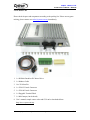
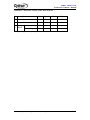
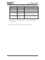
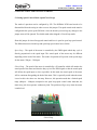
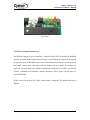
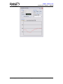
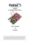
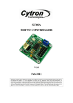
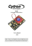
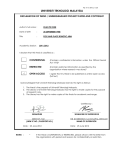
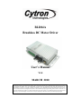
BLD04A
Brushless DC Motor Driver
User’s Manual
V1.0
MARCH 2010
Information contained in this publication regarding device applications and the like is intended through suggestion only and may
be superseded by updates. It is your responsibility to ensure that your application meets with your specifications. No
representation or warranty is given and no liability is assumed by Cytron Technologies Incorporated with respect to the accuracy
or use of such information or infringement of patents or other intellectual property rights arising from such use or otherwise. Use
of Cytron Technologies’s products as critical components in life support systems is not authorized except with express written
approval by Cytron Technologies. No licenses are conveyed, implicitly or otherwise, under any intellectual property rights.
ROBOT . HEAD to TOE
Product User’s Manual – BLD04A
Index
1. Introduction
1
2. Packing List
2
3. Product Specification and Limitations
3
4. Board Layout
4
5. Installation and Getting Started
9
5.1 Setting Speed Control Mode (Open/Closed loop)
9
5.2 UART Communication Protocol
10
5.3 Using BLD04A with AR40B/IFC-BL02
14
5.4 Using BLD04A with microcontroller (Parallel Mode)
17
5.5 Using BLD04A with microcontroller (UART Mode)
19
5.6 Using BLD04A with PC (UART Mode)
21
6. Warranty
Created by Cytron Technologies Sdn. Bhd. – All Rights Reserved
25
ROBOT . HEAD to TOE
Product User’s Manual – BLD04A
1. INTRODUCTION
BLD04A is designed to drive the Linix 10W and 30W brushless dc (BLDC) motor. It offers
several enhancements over the original Linix BLDC motor driver such as closed loop speed
control, UART interface and better protection for both the motor as well as the driver.
Besides that, the interface of BLD04A is compatible with the original Linix BLDC motor
driver and this makes the upgrading for existing users an effortless process. This BLDC
motor driver is designed with the capabilities and features as below:
•
Powered by high performance dsPIC Digital Signal Controller.
•
Operating at DC +24V ±15%.
•
Support up to 4A per phase.
•
4-Quadrant control.
•
5V logic level input for Start/Stop, Run/Brake, Direction and Alarm Reset.
•
Support analog voltage (0 – 5V) or PWM signal for speed control.
•
Support UART interface.
•
Selectable open loop or closed loop speed control.
•
Current limiter.
•
12 pulses per revolution encoder output.
•
Alarm indicator for overvoltage, undervoltage, out-of-phase and overload alarm.
•
Comes with casing for better durability and easier mounting.
•
Support the following Linix BLDC motor:
10 Watt:
45ZWN10-5G
45ZWN10-15G
45ZWN10-30G
30 Watt:
45ZWN30-10G
45ZWN30-20G
Created by Cytron Technologies Sdn. Bhd. – All Rights Reserved
1
ROBOT . HEAD to TOE
Product User’s Manual – BLD04A
2. PACKING LIST
Please check the parts and components according to the packing list. If there are any parts
missing, please contact us at [email protected] immediately.
1. 1 x BLD04A Brushless DC Motor Driver
2. 1 x Rainbow Cable
3. 16 x 2510 Iron Pin
4. 1 x 2510-12 Female Connector
5. 1 x 2510-04 Female Connector
6. 1 x Pluggable Terminal Block
7. 1 x Mini Jumper (On the board)
8. User’s manual, sample source codes and GUI can be downloaded from
http://www.cytron.com.my.
Created by Cytron Technologies Sdn. Bhd. – All Rights Reserved
2
ROBOT . HEAD to TOE
Product User’s Manual – BLD04A
3. PRODUCT SPECIFICATION AND LIMITATIONS
Parameters
No
Max
Typical
Min
Unit
1.
Input voltage
28
24
20
V
2.
Output Current (Per Phase)
4
-
-
A
3.
Speed
Open Loop*
3500
-
250
rpm
Closed Loop
3000
-
400
rpm
* The open loop speed may vary from motor to motor.
Created by Cytron Technologies Sdn. Bhd. – All Rights Reserved
3
ROBOT . HEAD to TOE
Product User’s Manual – BLD04A
4. BOARD LAYOUT
9
8
7
6
1
5
2
3
4
Components on BLD04A
1 2 3 4 5 6 7 8 9 10
97 5 31
12 34
10 8 6 4 2
BLD04A pins orientation
Components on BLD04A and their functions:
1. Fuse (5A) – To protect the BLD04A.
Created by Cytron Technologies Sdn. Bhd. – All Rights Reserved
4
ROBOT . HEAD to TOE
Product User’s Manual – BLD04A
2. Pluggable Terminal Block – Connect to motor and power source.
Pin No.
Pin Name
Wire Color
Description
1
+24V
Red
Positive supply.
2
Ground
Black
Negative supply.
3
Motor Coil A
White
Connect to motor coil A.
4
Motor Coil B
Blue
Connect to motor coil B.
5
Motor Coil C
Green
Connect to motor coil C.
6
+5V
Red
Positive supply to the hall sensor.
7
Ground
Black
Negative supply to the hall sensor.
8
Hall Sensor A
White
Connect to hall sensor A.
9
Hall Sensor B
Blue
Connect to hall sensor B.
10
Hall Sensor C
Green
Connect to hall sensor C.
3. FRC Header – Parallel IO interface
Pin No.
Pin Name
Description
1
Start/Stop*
Internally pulled high, active low.
2
Run/Brake*
Internally pulled high, active low.
3
Direction*
Internally pulled high, active low.
4
Alarm Reset*
Internally pulled high, active low.
5
VRH
Connect to the higher terminal of external
potentiometer for speed control.
6
Speed Input
PWM or analog voltage (0 – 5V) input for speed
control.
7
VRL
Connect to the lower terminal of external
potentiometer for speed control.
8
Ground
Logic ground.
9
Encoder Output**
Open Collector output, 12 pulses per revolution.
10
Alarm Output**
Open Collector output, active low.
* These pins are TTL / CMOS compatible and are internally pulled high. They can
be controlled by a microcontroller output or a switch.
** These pins are open collector outputs. When they are connected to the input of the
microcontroller, an external pull up resistor (1K – 10K Ohm).
Created by Cytron Technologies Sdn. Bhd. – All Rights Reserved
5
ROBOT . HEAD to TOE
Product User’s Manual – BLD04A
Pin 1 (Start/Stop) and pin 2 (Run/Brake) – These 2 pins are used together to
control the movement of the brushless motor. The effects of each pin are as follow:
Pin 1 (Start/Stop)
Pin 2 (Run/Brake)
Description
X (Don’t Care)
High
Motor stops instantaneously (brake)
High
Low
Motor stops naturally (free running stop)
Low
Low
Motor rotates
Pin 3 (Direction) – This pin controls the direction of the motor. The actual direction
of the motor depends on the gear ratio of the gearbox.
Linix BLDC Motor
45ZWN10-5G
Pin 3
(Direction)
Direction of the output shaft after gearbox
(As viewed into the output shaft)
High (1)
Counter-Clockwise
45ZWN30-20G
Low (0)
Clockwise
45ZWN10-30G
High (1)
Clockwise
45ZWN30-10G
Low (0)
Counter-Clockwise
45ZWN10-15G
Pin 4 (Alarm Reset) – When the error alarm is triggered, setting this pin to low level
will reset the alarm. Please return the Start/Stop or Run/Brake input to high level
before resetting the alarm. The alarm will not be reset if both inputs are at low level.
Pin 5 (VRH) – When speed control by potentiometer is desired, this pin is connected
to the higher pin of the potentiometer. Please refer to figure below for the connection.
Pin 6 (Speed Input) – The speed of the motor can be controlled by the analog voltage
(0 – 5V DC) or PWM signals on this pin. Please refer to figure below for the
connection.
Pin 7 (VRH) – When speed control by potentiometer is desired, this pin is connected
to the lower pin of the potentiometer. Please refer to figure below for the connection.
Created by Cytron Technologies Sdn. Bhd. – All Rights Reserved
6
ROBOT . HEAD to TOE
Product User’s Manual – BLD04A
Pin 8 (Ground) – Connect this pin to the ground of the host.
Pin 9 (Encoder Output) – The BLD04A will output 12 pulses per motor rotation
(before gearbox) on this pin. This can be used to determine the speed and number of
rotations for the motor.
Pin 10 (Alarm Output) – This pin will be triggered (pulled to low) when there is an
error occurred.
4. 2510-04 – UART interface.
Pin No.
Pin Name
Description
1
UART Rx
5V UART receive pin.
2
UART Tx
5V UART transmit pin.
3
Ground
Logic ground.
4
Not Connected
Leave this pin disconnected.
5. Test Button – When this button is pressed, the motor will rotate at speed 1000. This is
to fast check the condition of the BLD04A. (This does not work in serial control
mode).
6. Closed Loop Selection Jumper – Short this jumper for closed loop speed control, open
it for open loop speed control (This need to be configured before power on the board).
Created by Cytron Technologies Sdn. Bhd. – All Rights Reserved
7
ROBOT . HEAD to TOE
Product User’s Manual – BLD04A
7. Red LED – Error Alarm LED. The number of flashes indicates the type of alarm.
Number of Flashes
Alarm
Description
No Alarm
No error has been detected.
2
Overvoltage
Input voltage is > 28V
3
Undervoltage
Input voltage is < 20V
4
Out-Of-Phase
5
Overload
Off
The motor hall sensors state are invalid
(Bad motor or loose connection).
The motor has been overloaded for
more than 5 seconds.
8. Yellow LED – Speed Control Mode Indicator. Light on when closed loop speed
control is selected.
9. Green LED – Power LED. Light on when the board is powered up.
Created by Cytron Technologies Sdn. Bhd. – All Rights Reserved
8
ROBOT . HEAD to TOE
Product User’s Manual – BLD04A
5. INSTALLATION AND GETTING STARTED
5.1 Setting Speed Control Mode (Open/Closed Loop)
The mode of operation can be configured by JP2. The BLD04A PCB board needs to be
disassembled from the casing in order to access this jumper. The speed control mode must be
configured before power up the BLD04A. Once the board is powered up, any changes to the
jumper status will be ignored. The default mode when shipped is Closed Loop mode.
Short this jumper for closed loop speed control and leave it open for open loop speed control.
The different between closed loop and open loop speed control are as follow:
Open Loop – The speed of the motor is controlled by the PWM signal which duty cycle is
directly proportional to the speed input. The actual speed of the motor may be different
depending on the load of the motor. This mode of operation will provide wider speed range
for the motor (250rpm – 3500rpm).
Closed Loop – The speed of the motor is controlled by a PI controller which will monitor the
actual speed of the motor and alter the duty cycle of the PWM signal so that the actual speed
will follow the speed input as close as possible. In this mode, the actual speed of the motor
will be consistent disregarding the load of the motor. This is especially useful when the motor
is used to drive the robot over the ramp. However, this operation mode has a limited speed
range (400rpm – 3000rpm) compared to the open loop speed control. Other than that, the
motor may jerk when operates without any load. The problem will go away when the motor
is under load.
Closed Loop
Created by Cytron Technologies Sdn. Bhd. – All Rights Reserved
9
ROBOT . HEAD to TOE
Product User’s Manual – BLD04A
Open Loop
5.2 UART Communication Protocol
The BLD04A supports 2 types of interface – Parallel IO and UART. By default, the BLD04A
operates in parallel control mode where the motor is controlled by the input from the parallel
IO interface. Once the BLD04A receives any valid command from the host, it will operate in
the UART control mode since then and any changes on the parallel IO interface are
neglected. To return back to the parallel control mode, the host need to send a “Set Parallel
Control” command to the BLD04A. Another alternative will be power off and power on
again the BLD04A.
In this section, the protocol for UART control mode is explained. The default baud rate is
9600bps.
Created by Cytron Technologies Sdn. Bhd. – All Rights Reserved
10
ROBOT . HEAD to TOE
Product User’s Manual – BLD04A
Created by Cytron Technologies Sdn. Bhd. – All Rights Reserved
11
ROBOT . HEAD to TOE
Product User’s Manual – BLD04A
Testing UART Communication
To test the UART communication, the host need to send 3 bytes of data one by one to the
BLD04A. First 2 bytes are headers and third byte is command to test the UART
communication.
i. 1st byte: Send header 1 ‘0x00’
ii. 2nd byte: Send header 2 ‘0x00’
iii. 3rd byte: Send command ‘0xAA’
After sending 3 bytes of data, host will receive 3 bytes of data from the BLD04A.
i. 1st byte: Receive header 1 ‘0x00’
ii. 2nd byte: Receive header 2 ‘0x00’
iii. 3rd byte: Receive data ‘0xAA’
Set UART Baudrate
UART Baudrate can be set by sending 5 bytes of data from host to BLD04A. The value of
baudrate must only be 0 – 5.
i. 1st byte: Send header 1 ‘0x00’
ii. 2nd byte: Send header 2 ‘0x00’
iii. 3rd byte: Send command ‘0x22’
iv. 4th byte: Send data ‘0x00’
v. 5th byte: Send value of baudrate (0 – 5)
Stop/Brake/Run/Set Direction/Reset Alarm/Set Parallel Control
3 bytes of data need to be sent for stop, brake, run, set direction, reset alarm and set parallel
control. The first 2 bytes are headers and the third byte is the command to stop, brake, run, set
direction, reset alarm and set parallel control.
i. 1st byte: Send header 1 ‘0x00’
ii. 2nd byte: Send header 2 ‘0x00’
iii. 3rd byte: Send command to stop, brake, run, set direction, reset alarm and set
parallel control
Created by Cytron Technologies Sdn. Bhd. – All Rights Reserved
12
ROBOT . HEAD to TOE
Product User’s Manual – BLD04A
Set Speed
5 bytes of data is needed to control the speed of the motor. The value of the speed must only
be 0 – 3000.
i. 1st byte: Send header 1 ‘0x00’
ii. 2nd byte: Send header 2 ‘0x00’
iii. 3rd byte: Send command to set the motor speed ‘0xF6’
iv. 4th byte: Send MSB value of speed
v. 5th byte: Send LSB value of speed
Read Speed
Host need to send 3 bytes of data to read the motor speed. The value returned to the host is
the speed of the motor in rpm.
i. 1st byte: Send header 1 ‘0x00’
ii. 2nd byte: Send header 2 ‘0x00’
iii. 3rd byte: Send command ‘0xF8’
After sending 3 bytes of data, host will receive 4 bytes of data from the BLD04A.
i. 1st byte: Receive header 1 ‘0x00’
ii. 2nd byte: Receive header 2 ‘0x00’
iii. 3rd byte: Receive MSB value of speed
iv. 4th byte: Receive LSB value of speed
Read Alarm State
3 bytes of data will be sent to read the alarm state.
i. 1st byte: Send header 1 ‘0x00’
ii. 2nd byte: Send header 2 ‘0x00’
iii. 3rd byte: Send command ‘0xF9’
Then host will receive 4 bytes of data from BLD04A.
i. 1st byte: Receive header 1 ‘0x00’
ii. 2nd byte: Receive header 2 ‘0x00’
iii. 3rd byte: Receive data ‘0x00’
iv. 4th byte: Receive alarm value.
Created by Cytron Technologies Sdn. Bhd. – All Rights Reserved
13
ROBOT . HEAD to TOE
Product User’s Manual – BLD04A
5.3 Using BLD04A with AR40B / IFC-BL02
Guide for making 10 ways cable
This cable is used to interface Brushless Motor Driver with Parallel IO interface. 10 ways of
rainbow cable will be used on a 2510-12 female connector. 2 pins from 2510-12 connector
are unused which are pin1 and pin5.
1
2
3
4
5
6
7
1
12
*Pin 1 and pin 5 of 2510-12 connector is
not connected to any cable. (Unused)
Created by Cytron Technologies Sdn. Bhd. – All Rights Reserved
ROBOT . HEAD to TOE
Product User’s Manual – BLD04A
8
Please refer to IFC-BL02 User’s Manual for IFC-BL02 hardware installation.
Connect the driver with the brushless motor to IFC-BL02 as shown in below figure.
1. Connect Pluggable Terminal Block from brushless motor to BLD04A.
2. Connect power supply (thick red and black wire) to IFC-BL02 card.
3. Connect Parallel I/O cable from BLD04A to IFC-BL02.
1
2
Created by Cytron Technologies Sdn. Bhd. – All Rights Reserved
15
ROBOT . HEAD to TOE
Product User’s Manual – BLD04A
3
Pin
Connection
2
VCC
1
GND
Pin
Connection
12
Alarm Output
11
Encoder Output
10
Ground
9
VRL
8
Speed Input
7
VRH
6
Alarm Reset
5
NC
4
Direction
3
Run/Brake
2
Start/Stop
1
NC
Created by Cytron Technologies Sdn. Bhd. – All Rights Reserved
16
ROBOT . HEAD to TOE
Product User’s Manual – BLD04A
5.4 Using BLD04A with Microcontroller (Parallel Mode)
Sample source code is provided to show how to interface BLD04A with SK40B/SK40C in
Parallel Control Mode. The sample source code does not demonstrate all the features of
BLD04A.
The connection between the Parallel IO Interface of the BLD04A and the SK40B/SK40C is
as below:
For this sample source code, every time the SW1 is pressed and released, the motor will go
through the following cycle:
Free-Running Stop Rotate at half speed with direction 1 Brake Rotate at full speed
with direction 0 Repeat again
Created by Cytron Technologies Sdn. Bhd. – All Rights Reserved
17
ROBOT . HEAD to TOE
Product User’s Manual – BLD04A
Connect the BLD04A to microcontroller as shown in figure below. This example uses
SK40C as the host.
1. Connect Pluggable Terminal Block from brushless motor to BLD04A.
2. Connect power supply (thick red and black wire) to 24V power source.
3. Connect Parallel I/O cable from BLD04A to SK40C.
Created by Cytron Technologies Sdn. Bhd. – All Rights Reserved
18
ROBOT . HEAD to TOE
Product User’s Manual – BLD04A
5.5 Using BLD04A with Microcontroller (UART Mode)
Sample source code in UART mode is also provided to show how to use the BLD04A with
SK40C/SK40B in UART Control Mode. Sample source code can be downloaded from the
website. However, the sample source code does not demonstrate all the features of BLD04A.
For this sample source code, every time the SW1 is pressed and released, the motor will go
through the following cycle:
Free-Running Stop Rotate at half speed with direction 1 Brake Rotate at full speed
with direction 0 Repeat again
Created by Cytron Technologies Sdn. Bhd. – All Rights Reserved
19
ROBOT . HEAD to TOE
Product User’s Manual – BLD04A
Connect the BLD04A to microcontroller as shown in figure below. This example uses
SK40C as the host.
1. Connect Pluggable Terminal Block from brushless motor to BLD04A.
2. Connect power cable (thick red and black wire) to 24V power source.
3. Connect UART cable from BLD04A to SK40C.
Rx and Tx pin is
cross connected
Created by Cytron Technologies Sdn. Bhd. – All Rights Reserved
20
ROBOT . HEAD to TOE
Product User’s Manual – BLD04A
5.6 Using BLD04A with PC (UART Mode)
Besides controlling the BLD04A with a microcontroller, we also provide GUI to control the
motor from a PC. UC00A is needed for UART communication between BLD04A and PC.
Please refer to UC00A User’s Manual for more details about the product.
1. Connect Pluggable Terminal Block from brushless motor to BLD04A.
2. Connect power source wire (thick red and black wire) to 24V power source.
3. Connect UC00A to PC USB port and another end of UC00A to UART port of BLD04A.
Created by Cytron Technologies Sdn. Bhd. – All Rights Reserved
21
ROBOT . HEAD to TOE
Product User’s Manual – BLD04A
4. Open BLD04A GUI folder and click on ‘Setup’. BLD04A GUI can be downloaded from
the website. User may already have the .NET framework installed on PC, especially if
users have already installed other applications which were built with one of the Visual
Studio 2005 .NET languages. If you do not yet have it, the .NET framework can be
freely downloaded from Microsoft's website. Users of Windows Vista do not need to
install the .NET framework, as it comes pre-installed as part of the OS.
5. Click ‘Install’ to install the BLD04A GUI.
Created by Cytron Technologies Sdn. Bhd. – All Rights Reserved
22
ROBOT . HEAD to TOE
Product User’s Manual – BLD04A
6. Run the GUI. Warning massage may appear if you do not have any COM port on your
PC. Plug in the UC00A and click ‘OK’.
7. Figure below show the BLD04A GUI. Select the COM Port which is connected to the
BLD04A and the correct baud rate. The default baud rate is 9600bps.
8. Click ‘Connect’ and buttons for motor control will be enabled. The movement of the
motor can be controlled by clicking the corresponding button and the speed may be
changed by using the ‘Set Speed’ slide bar. Besides that, the motor speed can be
obtained by clicking the ‘Start’ button under the ‘Read Speed’ panel. The speed of the
motor will be ploted on the graph as shown below.
Created by Cytron Technologies Sdn. Bhd. – All Rights Reserved
23
ROBOT . HEAD to TOE
Product User’s Manual – BLD04A
Created by Cytron Technologies Sdn. Bhd. – All Rights Reserved
24
ROBOT . HEAD to TOE
Product User’s Manual – BLD04A
6. WARRANTY
Product warranty is valid for 6 months.
Warranty only applies to manufacturing defect.
Damage caused by miss-use is not covered under warranty.
Warranty does not cover freight cost for both ways.
Prepared by
Cytron Technologies Sdn. Bhd.
19, Jalan Kebudayaan 1A,
Taman Universiti,
81300 Skudai,
Johor, Malaysia.
Tel:
Fax:
+607-521 3178
+607-521 1861
URL: www.cytron.com.my
Email: [email protected]
[email protected]
Created by Cytron Technologies Sdn. Bhd. – All Rights Reserved
25