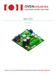
1
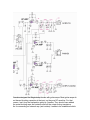
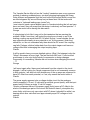
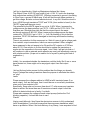
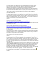
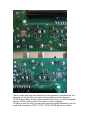
Magicstomp users should be aware of an "interesting" issue with some of them.
It seems a significant number have stray DC voltage on their outputs which can
cause a variety of problems depending on what the stomp is plugged into. This
ranges from mild to severe noise/distortion, treble cut or no sound at all, and is
particularly the case with older design valve amps such as the AC30. For most
modern equipment, there is no apparent problem, as they usually have input DC
filtering of their own, or are not affected by it.
To cut a long story short, Yamaha Australia confirmed
that ideally there should not be DC on the outputs but this could happen if certain
components fail or go "off spec". I have two stomps and both had the problem
which seems to me a pretty unlikely coincidence. On the other hand, David JM
also has two, one of which is OK.
IF you have this issue with your stomp, there is a workaround solution of external
cable with a 10uF capacitor in series with the active line and this does work. A
better solution is to have a Yamaha savvy technician do the fix inside the box. I
have just had one done ($75 AUD) and it has completely cured the problem.
Yamaha would not agree this is a possible design fault..
From: Charlie Hall
I just looked at the Magicstomp circuit in the service manual and there are
already blocking capacitors at the input and at the outputs. It could be that these
blocking capacitors are leaking DC. However, there are transistors after the
outputs that are for the mute function and this could also be a source of DC.
If anyone wants the service manual, please email me charliehallATntlworld.com
(replacing AT with &). I'm not sure whether the manual covers both earlier and
MkII models but there should be similarities.
Adding a 10uf cap in line will work but also adding a 100k resistor to earth after
the capacitor will ensure that any stray DC will be reduced before connecting the
output to anything else.
Regards,
Charlie
Hi Charlie,
Very interesting to read your assessment as the muting transistors were
considered the likely culprit by Yamaha's service manager though he was unable
to explain why they both would fail on each channel ... and for the issue to be so
apparently widespread. He also mentioned the existing blocking caps.
I asked the local service tech who did the actual fix what he had done. He was a
little vague but said it involved fixing (adding ?) some caps and resistors, and it
wasn't a design fault but that Yamaha did not envision the unit would be used
with DC sensitive equipment.
I'm sending my backup unit in today and will see if he can be a little more
specific.
George
Yamaha designed the Magicstomp for use with guitar amps. Most guitar amps do
not have a blocking capacitor at the input, so they are DC sensitive. For that
reason I can't buy the explanation given by Yamaha. They should have added
the extra blocking caps and resistors after all the output muting transistors.
As for connecting an external cap (and resistor) it needs to be established which
polarity the DC is so that the capacitor can be connected the correct way round.
Or instead, use a non polarised 0.1 capacitor with the same 100K resistor. It
would work fine with all high impedance inputs that it would connect into.
Regards,
Charlie
Could you send me a scan of the circuit diag with the muting transistors marked,
as I would like to go back to Yamaha again and see if they will accept this as not
up to best design practice and therefore should be fixed even if well outside
warranty.
Any further ideas as to why some amps are affected and others not, or what
might cause the problem in some stomps and not others ?
George
Almost all valve amps don't have a blocking input cap. A few older 50's Fenders
and also newer designs from various manufacturers do have them.
The self biasing of valves will be affected with any DC at the valve grid. Enough
voltage (usually around 2 volts) could cause the valve to go into its cut off region.
Less voltage than that will still shift the valve's operating point from where it
should be. This could easily cause the sound to change and the gain of the first
valve stage can change as well.
Some or even most solid state amps have blocking input caps but not all have
them.
I don't know if it's possible that the voltage at the transistor bases could change.
There is a part of the Magicstomp circuit that seems to operate all the mute
transistors so it could be to do with that part of the circuit which controls the
switching voltage going haywire.
Charlie
Thanks again, I have replied to your note.
It is beginning to look like this issue is much more widespread than realised but
has been masked because stomps are used with DC filtered amp inputs or are
not last in the effects chain. For example when I was in the UK in Feb and played
through a wide variety of amps, I was experimenting with a little Behringer
compressor pedal sometimes in front and sometimes after the stomp, and did not
have any problem. However at SMSE in Kent I tried straight from the stomp into
Jim Nugent's vintage AC30 and could not get a peep out of it much to everyone's
puzzlement. When plugged into a nearby Peavey or Laney ... no problem. In fact
it was hearing of this incident that alerted David JM (Gemini box) of this issue as
he had experienced something similar. One of his techies suspected DC as the
culprit and suggested to try the 10uF decoupling capacitor cable.
I'm feeling more confident in going back to Yamaha Australia with the evidence
that the output stage even if not "faulty" is at least not up to their normal high
standard and a refund for the cost of the fix is due.
George
Great to see a professional electronics guy's view on this. Not to labour the point,
but I first encountered the problem in July 2007, when I treated myself to a
"vintage" (1972) Vox AC30/6/TB.
As soon as I connected my Magic Stomp to any of the inputs, the amp "siezed" not a peep. No hum, nothing. It was as if it was receiving a jamming signal.
If I connected the Stomp to my Gemini III, that become nothing more that a
glorified distortion unit.
If I placed a secondary unit (in this case a solid state "Reel Echo") between the
Stomp and the Vox (or the Gemini III), all was well.
I asked my electronics guys to take a look at the Stomp, and although they didn't
delve too deeply, they couldn't find anything obvious. Their 'scope showed an
input and output sine-wave to be perfectly reproduced. However, when I
explained that a "buffer" device protected the amp, an afterthought was triggered,
and they suggested the decoupling capacitor in line with the signal path.
I modified a patch-lead and hey presto! I then got to hear of George's difficulties
while here in the UK - and a very loud bell started ringing !! The rest, as is said, is
history. The annoying bit is that I attend the SMSE meetings, and had I arrived
earlier at the February one, when George had his problems, I would have been
prompted to suggest the "fix" there and then.
Anyway, it all seems to be panning out. Thanks for your efforts. I think it's more of
a sleuthing exercise now. I've asked the electronics guys who build the Gemini to
take another look, now that they're armed with the schematics, thanks to you and
George.
By the way, I have a second stomp, preloaded with your patches, and I'm very
impressed. I particularly like the facility to extend the feedback.
David JM.
AC30 inputs don't have blocking capacitors so that explains why they are
affected by DC.
If the scope was set to AC input the fault would not show up. If set to DC input
the scope trace would have shifted vertically from the centre line.
Charlie
I have noticed that the Magicstomp muting transistor emitters are connected to
the outputs. If they had designed it so that the collectors were on the outputs and
the emitters were to earth (ground) like every other similar design I have seen,
then the problem wouldn't exist. Any voltage at the base of the transistor will be
transferred to the emitter (emitter follower) less 0.7 volts or so. Of course if the
voltage at the base was to exceed 0.7 volts, then the transistor could also be
overloaded with current. Maybe Yamaha thought that was a cheap way to avoid
current overload by ensuring that the emitters would always dump voltage to a
high impedance input. I would have done it a different way myself (not sure how
yet but I'm not exactly trying to redesign the Magicstomp for Yamaha).
Charlie
I think I understood all that. Surely, though, if a 10uF capacitor (apparently)
solved the problem, wasn't that all that was needed at manufacture?
I'm no electronics whizz-kid, as you can tell, but another, although somewhat farfetched thought has occurred. I note that the units are made in China.
I am in the manufacturing industry here in the UK, and fellow businessmen have
often observed that goods made in China quite often tend to move away from
specification after a period of time purely because "that's what the Chinese do" in
order to reduce their own costs, or because they feel like it! The leaded paint on
childrens' toys springs to mind. It's then up to the customer to snatch back the
reins as and when necessary. Perhaps Yamaha had fallen foul of such a
situation until realisation and correction. Or maybe Yamaha spotted the error
themselves, corrected it, and didn't tell anybody.
David JM
Hi David,
I think you are right about adding the capacitor internally (along with a 100K
resistor to earth to complete the job properly) but it would require this for each
output. To all, It would be good if we could verify whether earlier or later or both
versions are affected by this problem. Perhaps those with a problem could let us
know? I was also wondering whether the mute function is really necessary. If not,
maybe removing all the muting transistors would end the problems. There are
two transistors at each output. Still, it would be better to find a proper fix.
Charlie
I have three Stomps. Two of them has about -6,5V DC on the tip from MONO/L
output only. The RIGHT output has 0V DC. One of the faulty is a MK1, the other
faulty is a MK2. The one that not (yet) has this fault is a MK1. So as long as I use
the RIGHT output everything seems to work OK.
Kurt
Thanks for this information. It seems that the problem can exist in all models.
I am finding it difficult to diagnose the reason why one output is OK while the
other is not. The muting transistors are all fed from the same voltage supply so it
seems that the voltage supply is not the problem.
It is also difficult to understand why the outputs need a mute function.
Charlie
There is a muting when using the tuner function in the Stomp.
Kurt
The circuit diagram does not seem to show any link to a muting controller
function. The circuit that controls the transistors seems to only have connections
to the power supply. I haven't had time to delve right into all the details but it's not
apparent to me from the circuit alone how it works.
Charlie
The Yamaha Service Mgr told me the "muting" transistors were a very common
method of reducing unwanted pops, etc when plugging/unplugging the Stomp.
Quite different and separate from the front button mute action which is more like
an effects bypass. My second Stomp has just been fixed. All the tech would
volunteer is "replaced leaking caps, tested" etc.
I now intend to send a more detailed report to Yamaha including the info we have
here, and see if they will accept that the design is obviously not 'best practice". If
it were we would not be having this discussion.
George
It is beginning to look like it may not be the transistors that are causing the
problem. When I have time I will look at the circuit more closely to see if the
existing coupling cap would leak DC if it failed. By that, I mean whether the op
amp outputs are normally at zero potential or not. At the moment I think they
should be, so I do not understand why there should be DC even if the coupling
cap fails. Perhaps a failure further back from the output stages could cause a
voltage offset that is damaging the output coupling caps.
Charlie
It will be good to hear your more detailed opinion. What I find strange is why the
"failure" rate seems to be so high. The fact that both MK1 and 11 are involved
would seem to rule out a faulty batch of components or design changes.
Presumably it is something Yamaha did not envision when designing the circuit
... ??
George
I will report again after I have gone backwards from the outputs in the circuit
diagram. I will be looking for a single component that is not necessarily common
to both outputs. I will also look into whether any of the op amps are supposed to
have DC offset from earth potential, or if not, any reason that could cause it.
Charlie
The power supply appears to be a voltage doubler circuit for the analogue
circuits supplying +15 and -15 volts with an artificial ground (earth), with the input
power being of course a single 12 volt AC supply.
I think a component failure in the power supply could cause a DC offset in the
whole of the analogue parts of the circuit. But that still doesn't yet explain why
some faulty units have only one output with DC where it shouldn't be while I am
hearing about other units that have approximately equal DC voltage on both
outputs.
Charlie
I will try to describe why I think my Magicstomp behave like it does.
The Output R has -4,84V DC and output L has -4,16V. If I look in the drawings
both outputs has resistors R140/R155, 100kohm connected to ground. According
to Ohm´s law, a current 0f 48uA resp. 41uA will float through these resistors to
get this voltage. But also a closed electrical circuit. In my unit I think the circuit is
from AGND through transistors TR107 and Tr108, (from emitter to base!) to the
"MUTE" signal and the mute circuit.
The potential for the MUTE signal in my unit is -5,86V. When I measure the
voltage across the base resistors i get, R173 : 0,49V and for R175: 0,41V. The
Resistors are 10k which then tells me that the current here is the same
as through resistors R140/155. When I measure the voltage across the base
resistors for TR139/154 I get < 0,01V , (< 1uA). My thinking of this is that the
transistors TR107/108 has been damaged in some way and therefore leaking
this current.
There is no protection for this component so I think it’s easy to get a voltage peak
from outside, output connections, which can cause problem. Other voltages I
have measured in the unit seems to be Ok and the DC outputs on IC106 are
about 0,01V. One solution to fix this should be to replace the transistors or
maybe cut the copperline to the mute signal. I don´t think I will get into that so I
will continue to use an external serial capacitor as usual until somebody come up
with a better solution. (Hope not to make a fool of myself by writing this kind of
explanation..)
Leif
Initially I too wondered whether the transistors could be faulty. But if one or more
have shorted out, there might not be any signal output from that output.
Charlie
I did not find any better answer for this problem than the things you already
found. Perhaps the muting transistors have the purpose to eliminate the switchon "plop"
Jacob
Please measure the voltages relative to AGND at all 4 transistor bases (2 on
each output). If all are the same, then it could be one or more faulty transistors,
since one of your outputs is OK.
Specifically, there must not be more than about 0.7 volts across any transistor
base to emitter. But since there are 2 transistors at each output it could be
difficult to detect which one is faulty, if not both.
Please also measure the voltage at each output op amp (before the 10uf
blocking capacitor). It should be close to zero.
Charlie
Having read (although I don't have the electronics acumen to fully understand)
Leif's investigations, I note that he says that there are some transistors which
have no protection. When I first took delivery of my Stomp, I was surprised to find
no power-switch. It has always been my understanding that to simply "pull a
plug" can lead to spikes and surges, and even though we are dealing with
relatively small voltages, the components involved will probably be
proportionately delicate. Perhaps the suspect transistors have been affected by
the repeated and rather basic means of powering up-and-down of the unit ( ??).
I had to smile at Leif's conclusion that he will continue to use a capacitorinterrupted signal line......
It always slightly bothers me too when there is no on/off switch for anything that
can be mains or externally powered. But must admit I hadn't considered it in the
case of the Magicstomp as I don't own one myself. You could have a valid point.
I'd like to wait and see if Jacob has another go at his.
Charlie
Here is a link for the 2SC3326 specs:
http://www.datasheetcatalog.org/datasheet/toshiba/989.pdf
It is described as a transistor for muting and switching applications and has a low
on resistance of 1 ohm.
Here is another discussion about muting transistors:
http://www.audioasylum.com/forums/tape/messages/8768.html
All the discussions I have read so far about muting transistors in general advise
to remove them.
There have been a number of reports from Magicstomp owners about a brighter
(perhaps harsher?) sound. I am beginning to think that these muting transistors
could also be responsible for that complaint.
I will continue to look for more information.
Charlie
As mentioned both my MS were repaired by a local authorized Yamaha Tech. I
told him about my conversation with the Yamaha Aust Service manager who was
of the opinion after looking at the C Diag that faulty muting transistors could be
the cause. After the repairs and on his invoices all the Tech would say is repaired
leaky caps etc.
I opened up both Stomps which fortunately is pretty simple and could see no sign
(with a magnifying glass) of any work except on one (the almost unused backup
unit) both TR107 and TR108 have been disconnected/removed and the other
TR108 only. Attached a few pics where you may be able to see the TR's.
Although I was not able to measure the voltages before the repair, both channels
on both stomps were causing a problem .. now they both work fine.
Is it possible that in some cases TR108 causes a problem in both channels
George
I have no idea what may have been done to the apparently untouched one, but
obviously on the other the cure was to disconnect/remove the transistors.
TR108 is very unlikely to affect both channels even if faulty. It could conceivably
damage TR104, going by what I have seen on Jacob's diagram.
I'm going to stick my neck out now and say that the easiest permanent cure is to
remove all 4 transistors TR103, TR107, TR104, TR108. But just to confirm
something, when your Magicstomp (the one with the disconnected transistors) is
connected to your amp and the amp is already switched on and working, and
then you connect power to the Magicstomp afterwards, do you hear any noise at
switch on, when using either output? Don't be concerned about whether it will
sound wrong because you might be using the wrong output for mono, it's just for
a test.
Charlie
With the amp already on, switching on the MS makes a small plop with either
output channel. There doesn't seem to be any difference between the MS.
Normally of course I switch the MS on first and then there is no noise at all.
George
I am glad to hear that the noise at switch on is not a large amount. Of course, it is
always advisable to connect up any pedal that has no power switch first before
switching on the amp.
Charlie
Thanks for the pics, it is interesting to see voltages displayed in this way. I
remember rigging up a diode and a battery as a simple light detector for
measuring the time of output of a photographic flashgun. I was able to see the
flash duration on the scope.
It seems to me that the transistors TR103 and TR107 are just as likely to become
faulty.
I would avoid a polarised cap as the voltage could be positive or negative, I don't
know yet. I have seen both mentioned. If you are going straight to your amp, try a
0.1uf cap. 100 volts working should be ample. A 0.1 cap will be good for input
impedances of 100K or higher.
If you must use 10uf it would have to be an electrolytic or a tantalum, it might be
possible to use two polarised caps in series, with the polarity reversed on one of
them, in which case you would end up with 5uf (or better still if you can get a non
polarised type). I did this when I was modifying my hifi speaker crossovers (they
still work!). 10uf would be good for input impedances as low as 1K, probably too
low to feed a Magicstomp output into anyway, since its own output impedance is
almost 1K (2 X 470 ohm resistors in series), in which case the output signal
voltage would be halved.
Charlie
-Just another thought, did you notice that the filter capacitors of the + and supplies of the main power supply are two different values? I thought that was an
odd design when I saw it. It could be part of the reason for such a large spike at
switch on (without the transistors).
Charlie
The DC voltage problem is solved with the installation of the new transistors.
The adhere transistors with are fed from the same power source seems OK.
And yes there are more strange design concepts in the MagicStomp.
I will regularity check the output ports, to see if the DC voltage problem returns.
For me its not clear what caused the transistors (103,104,107 and 108) to fail.
The spikes, odd design, bad manufactured transistors, strange power supply
Jacob
You may be thinking on the right lines. I was also wondering whether the 10K
base resistors are allowing too much current sometimes.
Charlie
My electronics "Guru", of Gemini III fame has studied the schematics of the
Magic Stomp and emailed his thoughts just this morning.
I don't pretend to understand very much of it, but it appears that he, and those of
you with electronics experience, and lively grey cells are strongly in agreement.
He's right, of course, about the ageing valve amps - it was my 1972 Vox AC30
which brought all this to light. Perhaps I should get some of the capacitors
checked out......!!
His comment on the choice of downstream equipment also rings true - it appears
from the variety of reports and comments that the stomps work fine with some
gear, but not others.
Here's his text:
Hi Dave
This is how it looks to me. I will take the R output as an example. The output from
the opamp IC106/1 is decoupled by C133 (10uF 25V) but thereafter goes to a
mute circuit, and here I believe lies the problem! On power-up and power-down
the voltage rails and capacitors in the circuit do odd things and sometimes make
loud pops and bangs on the output. The mute circuit waits for things to settle
down before the outputs are let loose. During power-up the output signal is
clamped by transistors TR103,107. The current to turn on the transistors in
common collector mode will travel from the mute circuit (>+15V) to the base of
the transistor via the 10K resistors R139,173 and to deck via the 100K resistor
R140. This will clamp the output to deck during the power-up delay. When the
power-up delay expires the voltage on the base of TR103,107 will go to
something less than -15V letting the outputs go. This is all fine during power-up
but during normal use if for any reason the average DC level on outputs wander
negative by anything around -15V the outputs will start to "clip" on the negative
edges of the signal causing distortion (not the nice type!). If the average DC level
on the output goes much less than -15V the signal will be completely muted.
If when the the unit is in the failed mode, i.e. distorted or no output check the
headphone output, this I believe will be fine. It would check the theory. The cure
(10uF in the output) will work fine but in hind sight might want to be a low leakage
non-polarised type. The reason the outputs wander negative depends on what
it's plugged into. Is the problem common to ageing valve amp's? If so this could
be due to leaky capacitors and the high voltages knocking around in these
things. If not it will be specific to the device being used with the unit and would
require further investigation.
Simon
Finally, although Simon provided the original capacitor solution, in order to
conceal the fix within the cap of the jack plug, I now use a 10uF tantalum bead
capacitor. This is physically smaller, and non-polarised.
It's a truly interesting thread, and it does appear that my suspicions that my
stomp was the culprit all along have been proven. The spanner in the works, so
to speak, is the fact that my second stomp doesn't manifest the same problems !!
Oh dear..........
David JM.
I think Simon has come to more or less the same conclusion.
As mentioned previously, most valve amps do not have a capacitor at the input.
Any DC voltage at the input will throw the biasing of the first stage way off.
If an amp otherwise works fine, there is not really any reason to blame the amp
for what the Magicstomp would do to the signal.
Charlie