1
November 1999
LonWorks Communication
Module for PT-9000
MODEL PT-NTL-10
TM
SOLUTIONS
TM
A Kele Company
DESCRIPTION
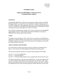
The PT-NTL-10 is the LonWorks Communication Module
for the PowerTrak PT-9000 Power Monitoring Interface.
The PT-NTL-10 reads data from the PT-9000’s main
processor, formats it, and transmits the data to a
LonWorks network using the LonTalk communications
protocol. The PT-NTL-10 allows all of the power system
parameters measured by the PowerTrak to be monitored over a single pair of wires using the LonWorks
FTT-10 Free Topology Transceiver. In addition, the
PT-9000 configuration switches, CT polarity, and voltage-current phasing settings can be monitored. Because
the PT-NTL-10 is designed to meet LonMark
Interoperability Guidelines, multiple PowerTraks can be
connected with other LonWorks devices on the same
network.
FEATURES
• Monitor all PowerTrak parameters over
a single pair of wires
• Allows remote reset (with time stamp)
of KWH and Peak KW parameters
• FTT-10 transceiver
• Standard Network Variable Types (SNVT)
are used to meet LonMark Interoperability
Guidelines
• Pluggable field wiring screw terminals
• Status LED indication
• Factory or field installation to any PT-9000
SPECIFICATIONS
Power supply
R
PT-NTL-10
WIRING
None required
(powered by PT-9000)
Network
LonWorks FTT-10 transceiver
Field wiring
Pluggable screw terminals
Dimensions
4.5''H x 2.6''W x 1.7''D
(11.4cm x 6.6cm x 4.3cm)
Operating
temperature
32 to 122°F (0-50°C)
Humidity
0-95% noncondensing
Weight
0.7 lb (0.32 kg)
Approvals
UL Listed, file #E161500
Certified to LonMark
Interoperability Guidelines
Version 3.1
PT-9000
Series
Ribbon
Cable
PT-NTL-10
Service Button
Service LED
FTT-10
CONTROL
MODULE
FT-10 NWK
KELE • www.kele.com • FAX 901-372-2531
Not Polarity
Sensitive
Status
LED
1
To LonWorks
FT-10 Network
USA 901-937-4900 • International 901-382-6084
INSTALLATION OF THE PT-NTL MODULE
If the PT-NTL option was ordered with the PT-9000, it will be pre-installed at Kele. If the PT-NTL is to be field
installed, follow these steps:
1. The main processor firmware must be at least Revision 1.3 for use with the PT-NTL option. If the label on your
main processor (large 40-pin IC chip in middle of PT-9000 upper board) shows a revision level less than 1.3,
contact Kele and we will send you an updated processor.
2. Ground yourself before removing the PT-NTL module from its anti-static bag. Both the PT-NTL and the Echelon
FTT-10 control module which mounts on top of the PT-NTL are static sensitive!
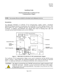
3. Unplug the Echelon FTT-10 control module from the top of the PT-NTL board. (See diagram below).
4. Lower the PT-NTL board over the two standoffs on the lower right corner of the PT-9000 sub-base. Orient
board so that the ribbon cable is on the upper left corner. Install the two 6-32 screws to secure the PT-NTL
board to the standoffs.
5. Plug the Echelon FTT-10 control module back onto the top of the PT-NTL board. Be careful to line up the
connector pins correctly!
6. Turn off the PT-9000 power using the System Voltage Select Switch. Plug the ribbon cable header from the
PT-NTL into the “Network Option” socket on the PT-9000 main processor board.
7. Turn the PT-9000 power back on. Connect the LonWorks network twisted pair to the 2-screw terminal block on
the lower right corner of the PT-NTL board. Information on LonWorks network wiring (topologies, terminating
resistors, wire types, etc.), can be found in Echelon Corporation publications such as the User’s Guide for the
FTT-10 Free Topology Transceiver.
8. This completes installation of the PT-NTL LonWorks Module.
ECHELON FTT-10
CONTROL MODULE
PLUGS INTO PT-NTL-10 BASE
RIBBON CABLE PLUGS INTO
"NETWORK OPTION"
SOCKET ON PT-9000
UPPER BOARD
STATUS
LED
PT-NTL-10
BASE BOARD
L-1
NT
PT0
SERVICE BUTTON
AND LED
EXISTING
STANDOFF
EXISTING
FT-10
STANDOFF
NETWORK
CONNECTION
KELE • www.kele.com • FAX 901-372-2531
ATE
SE PL
0 BA
PT-900
2
USA 901-937-4900 • International 901-382-6084
CONFIGURING THE PT-NTL LONWORKS MODULE ON THE NETWORK
Upon initial power-up, the PT-NTL red service LED will blink indicating that it is unconfigured. A third-party network
management software program running on a personal computer is required to configure the PT-NTL (and other
LonWorks nodes). The computer running the network management software may be removed from the system after
the network is configured or may remain for continuous monitoring of network variables and network status.
The PT-NTL LonWorks Module can be configured on the network in three ways:
1. If the network management software supports identification by Service Pin, the PT-NTL Service pushbutton can
be pushed when the network management software requests it. This causes an identification message to be
sent out on the network which will be picked up by the network management software.
2. The PT-NTL’s Neuron chip ID number can be entered manually into the network control console when requested
by the network management software. The Neuron chip ID number is written on the Echelon FTT-10 control
module in the format XX-XX-XX-XX-XX-XX.
3. If the network management software is capable of finding unconfigured nodes automatically, the Wink command
can be sent to the ID of each unconfigured node. Then the nodes can be physically checked to see which node
corresponds to which address. When the PT-NTL receives a Wink command, it blinks its Status LED rapidly
(5 times per second) for 5 seconds.
CLEARING NETWORK CONFIGURATION ON PT-NTL (SETTING UNCONFIGURED STATE)
If the network configuration in the PT-NTL ever needs to be cleared (put the PT-NTL in the Unconfigured State), this
can be accomplished by holding the Service button down while powering up the unit and continuing to hold the
Service button down for at least 7 seconds. After releasing the Service button, the red Service LED should begin to
flash to show that the PT-NTL has been reset to the Unconfigured State.
EXTERNAL INTERFACE (XIF) FILE
Each PT-NTL unit comes with a 3.5'' diskette containing documentation about the PT-NTL-10's network variables
and internal hardware configuration. The diskette contains the following:
A:\XIF_40\PTNTL102.XIF (Version 4.0 of External Interface File)
A:\XIF_31\PTNTL102.XIF (Version 3.1 of External Interface File)
A:\ResFiles\PTNTL102.TYP (User Resource "Type" File)
A:\ResFiles\PTNTL102.FPT (User Resource "Functional Profile Template" File)
A:\ResFiles\PTNTL102.FMT (User Resource "Format" File)
A:\ResFiles\PTNTL102.ENU (User Resource "US English Language" File)
A:\UserMan\PTNTL102.DOC (Microsoft Word version of this user's manual)
Most network management software will accept an XIF file when building the node's database. Version 4.0 of
the XIF file is preferred by the LonMaker network management software. Other third-party network management
software may prefer the 3.1 version of the XIF file. The XIF file is a plain text file. If ever in doubt as to which
version is being used, you may view the file with any text editor program and look at the version number in the
first-line header.
VERIFY OPERATION
After proper physical installation of the PT-NTL and configuration on the network, the green Status LED on the
PT-NTL will blink off once every five seconds. This indicates that the PT-NTL is requesting and receiving data from
the PT-9000. The red service LED will be off if the PT-NTL has been configured.
To verify communication over the network, you should be able to query any of the PT-NTL network variables
through the network management software tool. You can also use the network management software to cause the
PT-NTL to Wink. Issuing a Wink command from the network management software tool will cause the PT-NTL
green Status LED to blink five times per second for five seconds.
If the PT-NTL green Status LED is not blinking off once every five seconds, verify that the PT-NTL has been
properly installed by checking for loose or improper connections at the ribbon cable and the network terminal strip.
KELE • www.kele.com • FAX 901-372-2531
3
USA 901-937-4900 • International 901-382-6084
VERIFY OPERATION (CONTINUED)
If the PT-NTL green Status LED is blinking off once every five seconds but you are unable to communicate over the
network, verify that the PT-NTL has been properly installed on the network according to the installation process
described in the network management software documentation. Also, verify there are no breaks in the network
wiring between the PT-NTL and the network management software tool, and that the network is properly terminated.
PT-NTL-10 INTERFACE OVERVIEW
The PT-NTL-10 is LonMark certified to LonMark Interoperability Guidelines version 3.1. The PT-NTL-10 interface is
composed of a Node Object plus seven additional objects as shown below. The following sections discuss each of
the LonMark objects and the network variables associated with them.
PT-NTL-10
Interface Overview
Inputs
KELE • www.kele.com • FAX 901-372-2531
Object #0
Node Object
Outputs
Object #1
Power Measurement Object
Outputs
Object #2
Energy Measurement Object
Outputs
Object #3
Volts Measurement Object
Outputs
Object #4
Amps Measurement Object
Outputs
Object #5
VA Measurement Object
Outputs
Object #6
PF Measurement Object
Outputs
Object #7
PT Settings Object
Outputs
4
USA 901-937-4900 • International 901-382-6084
OBJECT 0 - THE NODE OBJECT
PowerTrak 9000 Node Object
Object #0
(Type #0)
Mandatory NVs
nv1 nviRequest
SNVT_obj_request
nv2 nvoStatus
SNVT_obj_status
Optional NVs
nv3 nviTimeSet
SNVT_time_stamp
nc22 nciMaxStsSendT SNVT_elapsed_time
Optional Config
Properties
Manufacturer
Specific NVs
nc22 nciMaxDatSendT
SNVT_elapsed_time
nvoPTTime
SNVT_time_stamp
Network input variable nviRequest allows the user to request information from or change the state of different
objects in the node. The nviRequest contains an object ID field that specifies which object receives the request.
The following request types are supported:
1. RQ_NORMAL (value 0) — If sent to Object 1, the Power Measurement Object, removes the object from the
Override Mode (explained below). If sent to Object 2, the Energy Measurement Object, removes the object from
the Override Mode (explained below). If sent to Object 0, the Node Object, removes both Object 1 and Object 2
from the Override Mode. Has no effect if sent to any other objects since they do not have override modes.
2. RQ_UPDATE_STATUS (value 2) — Requests the status of the object specified in the object ID field. If sent to
Object 0, the status response contains the status bits of all the node objects OR’ed together.
All objects support the status bit “unable_to_measure” which will be set if the PT-NTL is unable to get data from
the main processor. This should only occur if the main processor is doing an auto-configure, which is typically
done only during PT-9000 installation. When data is again available from the main processor, the
“unable_to_measure” bit in all object statuses will be reset.
Objects 1 and 2 support the status bit “in_override”. This bit will be set when the object receives a RQ_OVERRIDE command. This bit will be reset when the object is removed from override with a RQ_NORMAL
command.
3. RQ_REPORT_MASK (value 5) — Requests the object to report which status bits it supports. All objects support
the “unable to measure” status bit. Objects 1 and 2 support the “in_override” status bit. If sent to Object 0, report
has each status bit set which is supported by any object in the node (both “unable_to_measure” and “in_override”
bits will be set).
KELE • www.kele.com • FAX 901-372-2531
5
USA 901-937-4900 • International 901-382-6084
OBJECT 0 - THE NODE OBJECT (CONTINUED)
4. RQ_OVERRIDE (value 6) - If sent to Object 1, the Power Measurement Object, clears the Peak Sliding Window
Watts value which is kept in nonvolatile memory. If sent to Object 2, the Energy Measurement Object, clears the
WattHours count which is kept in nonvolatile memory. If sent to Object 0, clears both of the above values. If
sent to any other object, an “invalid_request” response is returned.
After a value is cleared using RQ_OVERRIDE, the value begins to update again in normal fashion even though
the object is still technically in override. Clearing the override state using RQ_NORMAL is strictly optional.
Network output variable nvoStatus returns the information requested by nviRequest. The status response will
indicate the status of the object that received the request. The following status fields are supported by the PT-NTL:
1. invalid_id
2. invalid_request
3. unable_to_measure
4. in_override
One nvoStatus response will be returned for each nviRequest. The configuration variable nciMaxStsSendT can
also be used to automatically send out status updates periodically (explained further below).
Network input variable nviTimeSet is used to set the internal time-of-day and date. The PT-NTL uses its internal
time and date to time stamp certain events (clearing watt-hour counter, clearing peak demand, logging new peak
demand).
If the user does not care to use time stamping in his application, the time and date can be ignored and need not be
set. No functions other than time stamping use the time and date.
Whenever the PT-NTL powers up, its internal time and date values are zeroed until new values are set using the
nviTimeSet input variable (the PT-NTL does not maintain time and date across power outages).
For best accuracy, the PT-NTL’s internal time should be updated using nviTimeSet at least once per day. Due to
crystal error and software uncertainties, the time could drift several minutes per day if uncorrected.
Network configuration variable nciMaxStsSendT allows the PT-NTL to automatically send out status updates at
regular time intervals if so desired. If nciMaxStsSendT is nonzero, the status of each object within the PT-NTL is
sent out round-robin fashion at the interval specified in nciMaxStsSendT. If nciMaxStsSendT is zero, status is only
sent out in response to nviRequest commands.
Network configuration variable nciMaxDatSendT allows the PT-NTL to automatically propagate all measurement
values at regular time intervals if so desired. If nciMaxDatSendT is nonzero, all measurement output variables
(except nvoPTTime) are sent out at the specified time interval. If nciMaxDatSendT is zero, measurements are
never sent out automatically, but they may be polled as desired by another node.
The minimum nonzero time supported by nciMaxDatSendT is 5 seconds. If nciMaxDatSendT is set to a nonzero
value less than 5 seconds, the PT-NTL will automatically convert it to 5 seconds.
The PT-NTL acquires new measurement values from the PT-9000 main processor every 5 seconds regardless of
the value of nciMaxDatSendT, so polling the measurement variables will always return current values even if
nciMaxDatSendT has been set to zero or a very large value.
Network output variable nvoPTTime will output the current time and date as maintained by the PT-NTL. Because
of poor long-term accuracy and the fact that the time and date are lost during a power outage, the PT-NTL’s time
and date should not be used to set the time on other nodes. The main use of nvoPTTime is to verify that the
PT-NTL’s time and date are valid.
Unlike other measurement output variables, nvoPTTime is not propagated when nciMaxDatSendT causes
automatic sending of measurements. This is because it is not needed on a regular basis by any other node.
KELE • www.kele.com • FAX 901-372-2531
6
USA 901-937-4900 • International 901-382-6084
OBJECT 1 - THE POWER MEASUREMENT OBJECT
PowerTrak 9000
Power Measurement Object
Object #1
(Type #20001)
Mandatory NVs
nv1 nvoTotWatts
SNVT_power_f
Optional NVs
nv2
nvoWinWatts
SNVT_power_f
nv3
nvoPkWnWatt
SNVT_power_f
nv4
nvoPhAWatts
SNVT_power_f
nv5 nvoPhBWatts
SNVT_power_f
nv6
nvoPhCWatts
SNVT_power_f
nv7
nvoPeakClrT
SNVT_time_stamp
nv8
nvoPeakLogT
SNVT_time_stamp
Network output variable nvoTotWatts is the total power (in Watts) measured by the PT-9000. The indicated value
is the instantaneous power (averaged over the last 7-8 seconds).
Network output variable nvoWinWatts is the total power (in Watts) measured in a 15-minute sliding window. The
value is recalculated every 30 seconds.
Network output variable nvoPkWnWatt is the peak sliding window value (in Watts) recorded since the last time
the peak was cleared (by overriding Object 1). The peak value is stored in nonvolatile memory and is retained during power outages.
Network output variable nvoPhAWatts is the instantaneous power (in Watts) for Phase A of the power
system. Valid for 3-phase wye, 1-phase 3-wire and 1-phase 2-wire power systems. Not valid for 3-phase delta
power systems.
Network output variable nvoPhBWatts is the instantaneous power (in Watts) for Phase B of the power
system. Valid for 3-phase wye, 1-phase 3-wire power systems. Not valid for 3-phase delta or 1-phase 2-wire power
systems.
Network output variable nvoPhCWatts is the instantaneous power (in Watts) for Phase C of the power
system. Valid for 3-phase wye power systems. Not valid for 3-phase delta, 1-phase 3-wire, or 1-phase 2-wire
power systems.
Network output variable nvoPeakClrT is a time stamp of when the last sliding window peak value was cleared (by
overriding Object 1). Only valid if time and date had been set to valid values (through nviTimeSet) prior to the clearing. This time stamp is stored in nonvolatile memory and is retained during power outages.
Network output variable nvoPeakLogT is a time stamp of when the peak sliding window value occurred. Only
valid if time and date had been set to valid values (through nviTimeSet) prior to the logging. This time stamp is
stored in nonvolatile memory and is retained during power outages.
KELE • www.kele.com • FAX 901-372-2531
7
USA 901-937-4900 • International 901-382-6084
OBJECT 2 - THE ENERGY MEASUREMENT OBJECT
PowerTrak 9000
Energy Measurement Object
Object #2
(Type #20002)
Mandatory NVs
nv1 nvoWattHr
SNVT_elec_whr_f
Optional NVs
nv2 nvoWattHrClrT
SNVT_time_stamp
Network output variable nvoWattHr is the total watt-hours of energy consumed since the last time the count was
cleared (by overriding Object 2). The watt-hour count is stored in nonvolatile memory and is preserved across
power outages.
Network output variable nvoWattHrClrT is a time stamp of when the watt-hours counter was last cleared. Only
valid if time and date had been set to valid values (through nviTimeSet) prior to the clearing. This time stamp is
stored in nonvolatile memory and is preserved across power outages.
OBJECT 3 - THE VOLTS MEASUREMENT OBJECT
PowerTrak 9000
Volts Measurement Object
Object #3
(Type #20003)
Mandatory NVs
nv1 nvoAvgVolts
SNVT_volts_f
Optional NVs
nv2 nvoL1Volts
SNVT_volt_f
nv3
nvoL2Volts
SNVT_volt_f
nv4
nvoL3Volts
SNVT_volt_f
Network output variable nvoAvgVolts is the average
value of all active line voltages on the power system.
For a 3-phase delta, this is the average of the three
line to line voltages. For a 3-phase wye, this is the
average of the three line to neutral voltages. For a
1-phase 2-wire system, this is the average of L1 to N
and L2 to N. For a 1-phase 2-wire system, this is just
L1 to N.
Network output variable nvoL1Volts is the value of
either L1 to L2 volts (3-phase delta system) or L1 to N
volts (3-phase wye, 1-phase 3-wire, 1-phase
2-wire systems).
Network output variable nvoL2Volts is the value of
either L2 to L3 volts (3-phase delta system) or L2 to N
volts (3-phase wye or 1-phase 3-wire systems). Not
valid for a 1-phase 2-wire system.
Network output variable nvoL3Volts is the value of
either L3 to L1 volts (3-phase delta system) or L3 to N
volts (3-phase wye system). Not valid for
1-phase 3-wire or 1-phase 2-wire systems.
KELE • www.kele.com • FAX 901-372-2531
8
USA 901-937-4900 • International 901-382-6084
OBJECT 4 - THE AMPS MEASUREMENT OBJECT
PowerTrak 9000
Amps Measurement Object
Object #4
(Type #20004)
Mandatory NVs
nv1 nvoAvgAmps
SNVT_amp_f
Optional NVs
nv2
nvoPhAAmps
SNVT_amp_f
Network output variable nvoAvgAmps is the average value of the power system current in amps. To
get total amps for a 3-phase system, multiply average
amps times 3. To get total amps for a 1-phase 3-wire
system, multiply average amps times 2.
Network output variable nvoPhAAmps is the Phase
A amps for the power system. Valid for all power system configurations.
Network output variable nvoPhBAmps is the Phase
B amps for the power system. Valid for 3-phase and 1phase 3-wire systems. Not valid for 1-phase, 2-wire
systems.
nv3 nvoPhBAmps
SNVT_amp_f
nv4 nvoPhCAmps
SNVT_amp_f
Network output variable nvoPhCAmps is the Phase
C amps for the power system. Valid for 3-phase power
systems. Not valid for 1-phase 3-wire or 1-phase
2-wire systems.
OBJECT 5 - THE VA (APPARENT POWER) MEASUREMENT OBJECT
PowerTrak 9000
VA Measurement Object
Object #5
(Type #20005)
Mandatory NVs
nv1 nvoTotVA
SNVT_power_f
Optional NVs
nv2 nvoPhAVA
SNVT_power_f
nv3
nvoPhBVA
SNVT_power_f
nv4
nvoPhCVA
SNVT_power_f
Network output variable nvoTotVA is the total volt-amps (apparent power) for the power system.
Network output variable nvoPhAVA is the volt-amps for Phase A of the power system. Valid for 3-phase wye,
1-phase 3-wire and 1-phase 2-wire power systems. Not valid for 3-phase delta systems.
Network output variable nvoPhBVA is the volt-amps for Phase B of the power system. Valid for 3-phase wye and
1-phase 3-wire systems. Not valid for 3-phase delta and 1-phase 2-wire systems.
Network output variable nvoPhCVA is the volt-amps for Phase C of the power system. Valid for 3-phase wye
systems. Not valid for 3-phase delta, 1-phase 3-wire or 1-phase 2-wire systems.
KELE • www.kele.com • FAX 901-372-2531
9
USA 901-937-4900 • International 901-382-6084
OBJECT 6 - THE POWER FACTOR MEASUREMENT OBJECT
Network output variable nvoTotPF is the total
power factor for the power system. It is calculated
as total watts divided by total volt-amps.
PowerTrak 9000
PF Measurement Object
Object #6
(Type #20006)
Mandatory NVs
nv1 nvoTotPF
SNVT_pwr_fact_f
Optional NVs
nv2 nvoPhAPF
SNVT_pwr_fact_f
nv3 nvoPhBPF
SNVT_pwr_fact_f
nv4 nvoPhCPF
SNVT_pwr_fact_f
Network output variable nvoPhAPF is the power
factor for Phase A of the power system. It is calculated as Phase A watts divided by Phase A voltamps. Valid for 3-phase wye, 1-phase 3-wire and
1-phase 2-wire systems. Not valid for 3-phase
delta systems.
Network output variable nvoPhBPF is the power
factor for Phase B of the power system. It is calculated as Phase B watts divided by Phase B voltamps. Valid for 3-phase wye, 1-phase 3-wire systems. Not valid for
3-phase delta or 1-phase 2-wire systems.
Network output variable nvoPhCPF is the power
factor for Phase C of the power system. It is calculated as Phase C watts divided by Phase C voltamps. Valid for 3-phase wye systems. Not valid
for 3-phase delta, 1-phase 3-wire or 1-phase 2-wire
systems.
OBJECT 7 - PT SETTINGS OBJECT
Network output variable nvoPTSettings is a
special User-defined Network Variable Type
(UNVT_PTSettings). It contains structures which
indicate the PT9000's dipswitch, rotary switch, CT
polarity, and V-I match settings. Its use is strictly
optional. Since it is not an industry standard SNVT,
custom programming may have to be done at the
receiving node to properly decode the information.
See Appendix A for a description of the UNVT_PT
Settings data structure.
PowerTrak 9000
PT Settings Object
Object #7
(Type #20007)
The User Defined Resource Files on the 3.5"
diskette also contain formatting information about
the special UNVT_PTSettings variable type. These
files may be used by some network manager software packages to automatically decode and display
nvoPTSettings without the need for any custom
programming.
nv1 nvoPTSettings
UNVT_PTSettings
nvoPTSettings does not propagate automatically
when nciMaxDatSendT is nonzero. This is because
switch settings rarely change once the unit has
been properly configured. nvoPTSettings may be
polled at any time as needed.
KELE • www.kele.com • FAX 901-372-2531
10
USA 901-937-4900 • International 901-382-6084
APPENDIX A
Decoding PT-9000 switch settings and power configuration through the structures in the network output
variable nvoPTSettings.
The data structures in nvoPTSettings contain information about the PT-9000 dipswitch settings, rotary voltage
switch settings, CT polarities, V-I matching, and whether the PT-9000 was manually or automatically power system
configured. Because this information does not fit into any industry-standard SNVT, a User-defined Network Variable
Type (UNVT) called UNVT_PTSettings was created. nvoPTSettings was then assigned the data type UNVT_PT
Settings. The layout of UNVT_PTSettings is given below:
typedef struct
{
struct
{
unsigned systype
unsigned lowvolts
}dipswa;
struct
{
unsigned kwhpp
unsigned ma2outsel
unsigned ma1outsel
}dipswb;
struct
{
unsigned rotswcode
unsigned ctratcode
}dipswc;
struct
{
unsigned ct_c_pol
unsigned ct_b_pol
unsigned ct_a_pol
unsigned auto_man
unsigned notused
}ctpolarity;
struct
{
unsigned notused
unsigned camps_match
unsigned bamps_match
unsigned aamps_match
}vimatch;
}UNVT_PTSettings;
// dipswitch A (top dipswitch) settings
:2;
:6;
// power system type select (2 top switches)
// low voltage threshold for alarm contacts (6 bottom switches)
// dipswitch B (middle dipswitch) settings
:2;
:3;
:3;
// KWH per pulse on pulse output (top 2 switches)
// mA output #2 function select (middle 3 switches)
// mA output #1 function select (bottom 3 switches)
// dipswitch C (bottom dipsw) and rotary switch settings
:3;
:5;
// 3-bit code shows rotary switch position
// CT ratio select (all 5 switches on dipswitch C)
// shows polarity for each current transformer
:1;
:1;
:1;
:1;
:4;
// C current transformer polarity (0 = normal, 1 = reverse)
// B current transformer polarity (0 = normal, 1 = reverse)
// A current transformer polarity (0 = normal, 1 = reverse)
// (0 = manual config, 1 = auto config)
// shows which input voltages are paired with which currents
:2;
:2;
:2;
:2;
// 2-bit code shows which voltage paired with C amps
// 2-bit code shows which voltage paired with B amps
// 2-bit code shows which voltage paired with A amps
network output UNVT_PTSettings nvoPTSettings; // simplified variable declaration
network output polled sd_string (“@7#1;PTSettings”) UNVT_PTSettings bind_info
(unackd) nvoPTSettings;
// full variable declaration from
//actual PT-NTL-10 neuron C code
KELE • www.kele.com • FAX 901-372-2531
11
USA 901-937-4900 • International 901-382-6084
APPENDIX A (CONTINUED)
For all dipswitch settings, a bit field = 1 indicates the switch is ON. The meanings of the different switches are
explained in the PT-9000 data sheet and on the labels on the inside of the PT-9000 door.
For the rotary switch settings, 3-bit code indicates switch position:
001 (decimal 1) = 120-144V
010 (decimal 2) = 190-277V
011 (decimal 3) = 346-415V
100 (decimal 4) = 440-480V
101 (decimal 5) = 600V
For V-I matching, 2-bit code indicates which voltage is paired with this particular current input:
00 (decimal 0) = L3 paired with this current
01 (decimal 1) = L2 paired with this current
11 (decimal 3) = L1 paired with this current
KELE • www.kele.com • FAX 901-372-2531
12
USA 901-937-4900 • International 901-382-6084