1
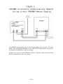
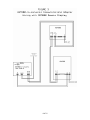
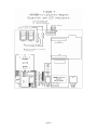
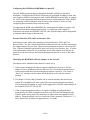
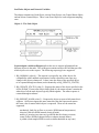
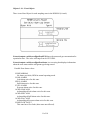
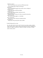
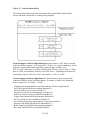
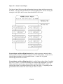
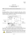
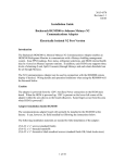
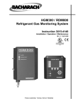
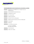
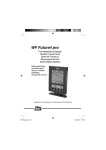
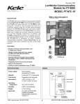
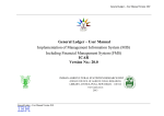
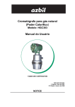
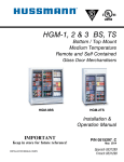
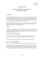
3015-4568
Revision 0
9/11/03
Installation Guide
Bacharach HGM300 to LonWorks FT-10
Communications Adapter
Introduction
The Bacharach HGM300 to LonWorks Communications Adapter enables an HGM300
Refrigerant Monitor to communicate with a LonWorks FT-10 Free Topology network.
Zone PPM readings, flow status, refrigerant selections, and HGM internal health may be
viewed over LonWorks. Each HGM zone supports three levels of alarming (Leak, Spill,
Evacuate) and each alarm threshold can be set over LonWorks.
The LonWorks Communications Adapter can be used in conjunction with the RDM800
remote display if desired. Wiring details and operation limitations when using the
RDM800 will be discussed later in this document.
Caution
The adapter is powered from the 120V Auxiliary Power connection on the HGM power
supply board. When the HGM is powered up, 120V is present on the lower left corner of
the adapter within the area shown on the board silkscreen. Keep fingers away from this
area when the HGM is powered!!
Adapter Installation Inside HGM300
The communications adapter board will normally be installed in the HGM300 at the
factory. It can, however, be field installed by following the instructions below.
The following installation materials are needed for field installation of the adapter:
(5) 6-32 x ¼” screws (standard finish)
(5) 6-32 x ½” threaded standoffs
(5) 6-32 x ¼” decorative black anodized screws (standard finish OK, black looks nicer)
The adapter board mounts on the rear of the HGM300 door. Position the adapter board
so as not to interfere with the HGM internal components when the door is shut. Mark
(Figure 1) and drill the board’s four corner holes and center hole in the door. Install the
five standoffs on the rear side of the door using the five black decorative screws on the
1 of 18
front side of the door. Position the adapter board over the standoffs mounted on the
HGM door. Install the five remaining 6-32 screws through the board and into the
standoffs and tighten.
Connect power wiring from the HGM300’s 120V Auxiliary Power terminal block to the
adapter board’s POWER terminal block. Use UL approved wire. Wire polarity does not
matter.
If an RDM800 remote display is NOT used with the adapter, refer to Figure 2 for wiring
details. In this case, all wiring between the HGM300 main board and adapter is
contained within the HGM300 and the only external cable is the LonWorks FT-10
communications cable.
2 of 18
If an RDM800 remote display IS to be used with the adapter, refer to Figure 3 for wiring
details. Note that when the RDM800 is used, TWO RS-485 cables must be run between
the HGM300 and RDM800, so plan accordingly.
In either case, be sure to set the HGM300’s internal “Terminator” slide switch next to the
RS-485 terminal block to the “In” position.
3 of 18
4 of 18
Setting HGM Communication Address On Adapter
See Figure 4 for the location of adapter dipswitch ‘A’.
Switches 5-8 on the adapter’s ‘A’ dipswitch are used to match the node address set on the
HGM’s address dipswitch (on HGM main board). Values from 0-15 are possible:
HGM address
----------------0
1
2
3
4
5
6
7
8
9
10
11
12
13
14
15
A5
A6
A7
A8
---------------------------------------------Off
Off
Off
Off
Off
Off
Off
On
Off
Off
On
Off
Off
Off
On
On
Off
On
Off
Off
Off
On
Off
On
Off
On
On
Off
Off
On
On
On
On
Off
Off
Off
On
Off
Off
On
On
Off
On
Off
On
Off
On
On
On
On
Off
Off
On
On
Off
On
On
On
On
Off
On
On
On
On
Since the HGM is the only node on the adapter-to-HGM interface, address 1 is normally
used. Be sure to set the same address on the adapter and the HGM main board
dipswitches.
5 of 18
6 of 18
Configuring the HGM300 with RDM800 or Laptop PC
The only HGM parameters that are changeable through LonWorks are the alarm
thresholds. Configuring the HGM for refrigerant type and length of tubing for each zone
(zero length to disable a zone) must be done with the RDM800 remote display or a laptop
PC. Refer to the appropriate Bacharach instructions for configuring these items. HGMs
are commonly custom-configured at the factory per the customer’s needs, so field
configuring these parameters may not be necessary.
If configuring the HGM with an RDM800, the communications adapter’s presence will
not affect the standard configuration procedure. If configuring with a laptop PC,
temporarily disconnect the HGM300’s RS-485 cable from the adapter until configuration
is complete and the laptop is disconnected.
External Interface (XIF) and User Resource Files
Each adapter comes with a disk containing an External Interface (XIF) and User
Resource files. The files contain documentation about the network variables contained in
the adapter and how they are used. Most network management software will accept XIF
files. Echelon LonMaker (and possibly others) will accept User Resource files. A subset
of the information in these files is permanently stored in the adapter itself and may be
queried over the network once the network management software is aware of the node’s
presence.
Identifying the HGM300-LonWorks Adapter on the Network
The adapter can be identified on the network in three ways:
1. If the network management software supports identification by Service Pin, the
adapter’s Service pushbutton (directly above the FT-10 twisted pair terminal block)
can be pushed when the network management software requests it. This causes a
“here I am” message to be broadcast which should be received by the network
manager.
2. The adapter’s Neuron chip ID number can be entered manually into the network
control PC or handheld tool when requested by the network management software.
The Neuron chip ID number is written on the piggyback LonWorks control module in
the format XX-XX-XX-XX-XX-XX.
3. If the network management software is capable of finding unconfigured nodes
automatically, the Wink command can be sent to the ID of each unconfigured node.
Then the nodes can be physically checked to see which node corresponds to which
address. When the adapter receives a LonWorks Wink command, it flashes its 1, 2, 5,
and 6 Status LEDs in unison for approximately 15 seconds.
7 of 18
HGM Alarm Acknowledge Options
Two alarm acknowledge options are supported—Auto Acknowledge and Network
Acknowledge.
In the Auto Acknowledge mode, the HGM will clear its alarm outputs the next time the
alarmed zone is sampled and its PPM has dropped below the alarm thresholds. No
intervention from the LonWorks network is necessary.
In the Network Acknowledge mode, the HGM will never clear its alarm outputs until
LonWorks has acknowledged the alarms using network variables nviHgmAlmAck or
nviHgmAlmAckSw (discussed below). Once LonWorks has acknowledged the alarms,
the HGM will clear its alarm outputs the next time the alarmed zone is sampled and its
PPM has dropped below the alarm thresholds.
Dipswitch A1 on the adapter selects which alarm acknowledge option is used:
A1 On = Auto Acknowledge
A1 Off = Network Acknowledge
If dipswitch A1 is changed while the adapter is powered up, the adapter must be reset by
pressing the CPU RST button below dipswitch A before the change will take effect.
8 of 18
LonWorks Objects and Network Variables
The adapter contains one Node Object, sixteen Zone Objects, one General Status Object,
and one Alarm Control Object. There is one Zone Object for each refrigerant sampling
zone.
Object 0 – The Node Object
Network input variable nviRequest allows the user to request information from
different objects in the node. The nviRequest contains an object ID field that specifies
which object receives the request. The following request types are supported:
1. RQ_NORMAL (value 0) – This request is accepted by any of the objects for
compatibility with LonMark requirements, but the request does not cause any
change in the objects whatsoever. It does cause the status of the specified object
to be reported through nvoStatus (works identically to RQ_UPDATE_STATUS).
2. RQ_UPDATE_STATUS (value 2) – Requests the status of the object specified in the
object ID field. If sent to the Object Node (Node 0), the status response contains the
status bits of all the node objects logically ORed together. The status response is
returned through nvoStatus.
3. RQ_REPORT_MASK (value 5) – Requests the object to report which status bits it
supports. All objects support the same status bits, thus the report mask returns
the same value no matter which object is requested. These are the status bits
supported:
mechanical_fault (for no flow or excessive HGM internal temperatures)
electrical_fault (for HGM internal electrical faults)
unable_to_measure (any time can’t get HGM data for whatever reason)
comm_failure (HGM-to-adapter failure or adapter internal failure)
in_alarm (when sampled PPM exceeds an alarm threshold on any zone)
9 of 18
Network output variable nvoStatus returns the information requested by nviRequest.
The status response will indicate the status of the object that received the request. The
status bits supported are listed above under RQ_REPORT_MASK.
One nvoStatus response will be returned for each nviRequest. The configuration
variable nciMaxStsSendT can also be used to automatically send out status updates
periodically. If nciMaxStsSendT is set to a nonzero time value, the node sends out a
status update on each expiration of that amount of time. It rotates through the objects on
the node in round-robin fashion when timed updates are sent in this manner. Any zone
which is disabled or not installed will have its zone object skipped in this automatic
round-robin reporting.
Setting nciMaxStsSendT to a very small value will cause unnecessary traffic on the
LonWorks network. A value of less than 500 milliseconds will, in fact, be ignored. A
suggested value for nciMaxStsSendT might be in the range of 10-60 seconds. If timed
automatic status updates are not desired, set nciMaxStsSendT to zero. Then status
updates will only be sent in response to nviRequest updates.
10 of 18
Objects 1-16 – Zone Objects
There is one Zone Object for each sampling zone in the HGM300 (16 total):
Network output variable nvoHgmZonePPM shows the measured gas concentration for
a particular zone. The value will range from 0-65535 PPM.
Network output variable nvoHgmZoneStatus is a text string that displays information
about the zone status and the refrigerant type being sensed.
Possible Zone Status values:
ZONE NORMAL
No alarms, no faults, HGM in normal operating mode.
LEAK ALARM
Leak alarm active for this zone.
SPILL ALARM
Spill alarm active for this zone.
EVAC ALARM
Evacuate alarm active for this zone.
ACKD LEAK ALM
Acknowledged Leak alarm active for this zone.
ACKD SPILL ALM
Acknowledged Spill alarm active for this zone.
ACKD EVAC ALM
Acknowledged Evacuate alarm active for this zone.
ZONE FLOW FAULT
This zone has a flow fault (other zones not affected).
11 of 18
CRITICAL FAULT
Some critical fault prevents normal zone PPM measurement.
(View nvoHgmFaults for details on fault type)
HGM BUSY
Occurs with RDM800 installed when certain screens are displayed.
COMM FAULT 1
Comm failure between HGM and adapter.
COMM FAULT 2
Comm failure between adapter internal processors.
HGM WARMING UP
HGM must go thru warmup cycle after powerup before measuring.
ZONE DISABLED
This zone has tubing length set = 0 (disabled).
NOT_INSTALLED
This zone does not have hardware installed in HGM.
STARTING UP
Startup delay after powerup before data available.
Possible Refrigerant Type values:
R11, R12, R22, R23, R113, R114, R123, R124, R134A, R401A, R402A, R402B,
R404A, R407A, R407C, R409A, R410A, R500, R502, R503, R507, R508B, H1301,
R408A, FUTURE2, FUTURE3, FUTURE4, FUTURE5, FUTURE6, FUTURE7,
NEW1, NEW2, NEW3
12 of 18
Object 17 – General Status Object
The General Status Object provides information about any HGM300 internal faults
present and shows which zone is currently being sampled:
Network output variable nvoHgmFaultAlert reports whenever ANY fault is detected
within the HGM or adapter. It is of type SNVT_switch. It is useful for binding to a Fault
lamp on a remote annunciation panel using a network input variable of type
SNVT_switch. When there is no fault, nvoFaultAlert will have value=0, state=0. When
there is a fault, nvoFaultAlert will have value=200, state=1. Depending on the network
presentation software, full-scale “value” may display as “200” or “100.0”.
Network output variable nvoHgmFaults (bit field structure) reports various faults
within the HGM300 or the LonWorks adapter. It contains 14 faults (1-bit fields) that
may be reported (0 = No Fault, 1 = Fault):
Clipping fault (internal HGM measurement fault)(bit 15)(most significant bit)
Zero Fault (internal HGM measurement fault)(bit 14)
No Flow Fault (no flow on any zone)(bit 13)
Purge Flow Fault (no flow during purge cycle)(bit 12)
Zone Flow Fault (no flow on a particular zone)(bit 11)
Trigger Fault (internal HGM measurement fault)(bit 10)
No Zones Fault (no zones enabled in HGM)(bit 9)
mA Loop Fault (mA loop output [option] is open circuited)(bit 8)
Pressure Fault (HGM bench pressure abnormal)(bit 7)
Bench Temp Fault (HGM bench temp abnormal)(bit 6)
Box Temp Fault (HGM box temp abnormal)(bit 5)
13 of 18
HGM Busy (if RDM800 attached and showing certain screens)(bit 4)
Comm Fault 1 (communications failed between HGM and adapter)(bit 3)
Comm Fault 2 (internal communications failed within adapter)(bit 2)
Unused (bit 1)
Unused (bit 0)(least significant bit)
Network output variable nvoZoneSampling shows which zone is currently being
sampled by the HGM. It is a number 1-16. Note that if fewer than 16 zones are installed,
nvoZoneSampling will never go larger than the largest zone installed. Also if a zone is
disabled (by setting its tubing length to zero), that zone number will be skipped by
nvoZoneSampling.
14 of 18
Object 18 – Alarm Control Object
The Alarm Control Object provides information about any alarms which are present in
the HGM. It also provides mechanisms for acknowledging alarms, and for viewing and
setting the Leak, Spill, and Evacuate alarm thresholds for each zone:
Network input variable nviHgmAlarmAck has a single parameter (unsigned short)
which specifies which zone alarm the operator wishes to acknowledge. A value of 1-16
acknowledges the alarm for a single specified zone. A value of 0 is a global
acknowledge for all zones in alarm.
Network input variable nviHgmAlmAckSw is a global alarm acknowledge of standard
type SNVT_switch. It is useful for binding to an Acknowledge pushbutton on a remote
alarm annunciation panel using a network output variable of type SNVT_switch. To
acknowledge alarms, set nviHgmAlmAckSw to value=200, state=1. Depending on the
presentation software, full-scale “value” may be “200” or “100.0”.
15 of 18
Network input variable nviSetZoneThresh allows Leak, Spill, and Evacuate alarm
thresholds (in PPM) to be set for each monitoring zone. nviSetZoneThresh has four
parameters to be set by the user:
Zone Specifier:
a number 1-16 specifies which zone is having its thresholds changed
Leak Alarm Threshold:
a number 0–65535 PPM
Spill Alarm Threshold:
a number 0-65535 PPM (larger than Leak Threshold)
Evacuate Alarm Threshold:
a number 0-65535 PPM (larger than Spill Threshold)
Network input variable nviGetZoneThresh accepts a single number 1-16 to specify
which zone’s alarm thresholds should be displayed on network output variable
nvoHgmZoneThresh.
Network output variable nvoHgmAlarmAlert reports whenever ANY gas
concentration alarm (Leak, Spill, or Evacuate) is generated by the HGM. It is of type
SNVT_switch. It is useful for binding to an Alarm lamp on a remote annunciation panel
using a network input variable of type SNVT_switch. When there are no alarms,
nvoAlarmAlert will have value=0, state=0. When there is any alarm, nvoAlarmAlert will
have value=200, state=1. Depending on presentation software, the full-scale “value” may
show as either “200” or “100.0”.
Network output variable nvoHgmLeakAlert reports whenever any Leak alarm is
generated by the HGM. It is of type SNVT_switch. It is useful for binding to a Leak
Alarm lamp on a remote annunciation panel using a network input variable of type
SNVT_switch. When there are no Leak alarms, nvoLeakAlert will have value=0, state=0.
When there are any Leak alarms, nvoLeakAlert will have value=200, state=1.
Network output variable nvoHgmSpillAlert reports whenever any Spill alarm is
generated by the HGM. It is of type SNVT_switch. It is useful for binding to a Spill
Alarm lamp on a remote annunciation panel using a network input variable of type
SNVT_switch. When there are no Spill alarms, nvoSpillAlert will have value=0, state=0.
When there are any Spill alarms, nvoSpillAlert will have value=200, state=1.
Network output variable nvoHgmEvacAlert reports whenever any Evacuate alarm is
generated by the HGM. It is of type SNVT_switch. It is useful for binding to an
Evacuate Alarm lamp on a remote annunciation panel using a network input variable of
type SNVT_switch. When there are no Evacuate alarms, nvoEvacAlert will have
value=0, state=0. When there are any Evacuate alarms, nvoEvacAlert will have
value=200, state=1.
16 of 18
Network output variable nvoHgmZoneThresh displays the following information for
the zone specified by nviGetZoneThresh:
1.
2.
3.
4.
Zone (1-16) whose alarm thresholds are being displayed
Leak Alarm Threshold in PPM (0-65535)
Spill Alarm Threshold in PPM (0-65535)
Evacuate Alarm Threshold in PPM (0-65535)
To change the Leak, Spill, or Evacuate alarm thresholds for a zone, use the
nviSetZoneThresh input network variable as described earlier.
Operating Limitations When Using RDM800 Remote Display
When an RDM800 remote display is used, LonWorks will have access to the HGM300 as
long as the RDM800 is in either the SYSTEM or ZONE VIEW screen. If the RDM800 is
set to display any other screen, it will respond to polls from the LonWorks adapter with
an HGM BUSY exception code. The LonWorks adapter will handle the exception by
setting all the zone statuses = HGM BUSY. When the RDM800 is returned to the
SYSTEM or ZONE VIEW screen, normal LonWorks monitoring will resume.
If the operator leaves the RDM800 in some screen other than SYSTEM or ZONE VIEW
for an extended period of time (10 minutes default), the RDM800 times out and
automatically returns to either the SYSTEM or ZONE VIEW screen. This will restore
normal LonWorks monitoring.
Communications LED Indicators
See Figure 4 for the locations of the communications LED indicators.
The communications adapter board has four LED communications status indicators
numbered 1-4. The meanings of these indicators are as follows:
LED 1 ON: Adapter is transmitting a poll/command to the HGM300
LED 2 ON: Adapter is receiving a response from the HGM300
LED 5 ON: Adapter internal communications (response from RCM CPU
to Neuron CPU)
LED 6 ON; Adapter internal communications (poll/command from Neuron CPU
to RCM CPU)
Under normal conditions, LEDs 5 and 6 will show a burst of alternating blinks about
every 8 seconds. This indicates that the two processors internal to the LonWorks adapter
are communicating with each other normally. Occasionally LEDs 5 and 6 will blink
more frequently if commands (to change alarm thresholds, for example) are coming in
from the LonWorks network.
17 of 18
LED 1 and LED 2 will normally show activity about every 15 seconds. Since the
refrigerant monitoring process is fairly slow and new data is only available every 15
seconds or so, the adapter polls the HGM at a slow rate to reduce the communications
burden on the HGM main processor. Again, commands coming in from LonWorks
might occasionally cause LEDs 1 and 2 to blink more frequently.
Operating Notes
Before changing alarm thresholds through nviSetZoneThresh, go ahead and set
nviGetZoneThresh to the zone you are about to modify. Then nvoHgmZoneThresh will
update automatically with the current thresholds for that zone every time new information
is available from the HGM300.
Please note that it could take as much as 30-40 seconds before the changes made through
nviSetZoneThresh can be seen on nvoHgmZoneThresh. The adapter must get the
changes from LonWorks and pass the new thresholds down to the HGM. The HGM then
takes a certain amount of time to process the changes and store them in its nonvolatile
memory. Then, since the HGM is not polled continuously, a certain amount of time is
needed to pick up the new threshold settings and pass them back up to LonWorks. Please
be patient waiting for changed alarm thresholds to show up in nvoHgmZoneThresh.
Fortunately changing alarm thresholds is done infrequently after initial installation and
setup.
If the adapter is moved to a new LonWorks network where the old addressing
information would be invalid, the adapter can be set back to its initial Unconfigured state.
This is accomplished by holding the Service button down, powering up the adapter, and
continuing to hold the Service button down for 10 seconds. When the Service button is
released, the Service LED will flash, showing that the LonWorks portion of the adapter is
now Unconfigured. This is the desired state for installing the adapter on a new
LonWorks network.
18 of 18