1
CodeWarrior Development Studio for
Power Architecture Processors
Getting Started Guide
Document Number: CWPAGS
Rev. 10.5.0, 06/2015
CodeWarrior Development Studio for Power Architecture Processors Getting Started Guide, Rev. 10.5.0,
06/2015
2
Freescale Semiconductor, Inc.
Contents
Section number
Title
Page
Chapter 1
Introduction
1.1 System Requirements........................................................................................................................................................5
1.2 Installing CodeWarrior..................................................................................................................................................... 6
1.3 Supported Devices............................................................................................................................................................ 7
Chapter 2
Configuring Target Hardware
2.1 Configuring B4420 QDS Board........................................................................................................................................9
2.2 Configuring B4860 QDS Board........................................................................................................................................10
2.3 Configuring P4080DS Board............................................................................................................................................12
2.4 Configuring BSC9131/G1110 RDB Board...................................................................................................................... 14
2.5 Configuring BSC9132 QDS Board...................................................................................................................................17
Chapter 3
Working with Projects
3.1 Launching CodeWarrior IDE............................................................................................................................................21
3.2 Creating Projects...............................................................................................................................................................22
3.2.1 Creating CodeWarrior Bareboard Application Project.......................................................................................... 23
3.2.2 Creating CodeWarrior Bareboard Library Project.................................................................................................26
3.2.3 Creating CodeWarrior Linux Application Project................................................................................................. 27
3.3 Building Projects...............................................................................................................................................................30
3.3.1 Manual-Build Mode............................................................................................................................................... 30
3.3.2 Auto-Build Mode................................................................................................................................................... 30
3.4 Debugging Projects...........................................................................................................................................................31
3.4.1 Debugging Bareboard Application Projects.......................................................................................................... 31
3.4.2 Debugging Linux Application Projects..................................................................................................................33
3.4.3 Debugging Guest LWEs Using Hypervisor...........................................................................................................36
3.4.4 Debugging Guest Linux Kernels Using Hypervisor.............................................................................................. 43
3.4.5 Debugging U-Boot................................................................................................................................................. 50
CodeWarrior Development Studio for Power Architecture Processors Getting Started Guide, Rev. 10.5.0,
06/2015
Freescale Semiconductor, Inc.
3
Section number
Title
Page
3.5 Deleting a Project..............................................................................................................................................................52
CodeWarrior Development Studio for Power Architecture Processors Getting Started Guide, Rev. 10.5.0,
06/2015
4
Freescale Semiconductor, Inc.
Chapter 1
Introduction
This Getting Started guide explains how to install the CodeWarrior software, prepare the
boards supported by the current release, and then create, build, and debug a simple
project.
This chapter contains:
• System Requirements
• Installing CodeWarrior
• Supported Devices
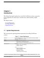
1.1 System Requirements
This section provides operating platform requirements for installing CodeWarrior
software.
Table 1-1. System Requirements
Processor
Intel® Pentium® 4 processor - 2 GHz or faster, Intel Xeon™, Intel Core™, AMD
Athlon™ 64, AMD Opteron™, or higher
Memory
2 GB RAM
Hardware
Operating System
• CD-ROM drive for CD installation
• Microsoft Mouse compliant pointing device
• Internet connectivity for web downloads and update access
Windows:
• Windows 7 SP1 (32-bit and 64-bit)
• Windows 8.1 (64-bit)
Linux:
• Ubuntu 12.04 (64-bit)
• Ubuntu 14.04 (32-bit and 64-bit)
• Ubuntu 15.04 (64-bit)
• OpenSUSE 13.2 (64-bit)
Table continues on the next page...
CodeWarrior Development Studio for Power Architecture Processors Getting Started Guide, Rev. 10.5.0,
06/2015
Freescale Semiconductor, Inc.
5
Installing CodeWarrior
Table 1-1. System Requirements (continued)
•
•
•
•
•
Mint 15 (64-bit)
Fedora 20 (64-bit)
Debian 7.6 (64-bit)
CentOS 7.0 (64-bit)
RHEL 6.5 (64-bit)
NOTE: Other Linux distributions could be used, but will likely require more manual
identification and installation of missing, required libraries.
Disk space
2.3 GB, additional space required during installation
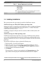
1.2 Installing CodeWarrior
This section provides the steps required to install the CodeWarrior software.
CodeWarrior usage on a Microsoft® Windows operating system:
Administrator rights are required to install CodeWarrior software on Microsoft Windows
7 operating system, since the installer copies files into the System folder. The default
CodeWarrior installation folder is C:\Freescale.
In addition, your project workspace must be created in a folder to which you have full
access rights.
CodeWarrior usage on a Linux operating system:
CodeWarrior installer must be run from a root account. CodeWarrior needs read/write
access to the installation folder. Ensure that the CodeWarrior installation folder has the
appropriate permissions for all users, and your project workspace has the read and write
permission.
To install the CodeWarrior software, perform the following steps:
1.
2.
3.
4.
5.
Run the installer - the install wizard appears.
Follow the wizard's on-screen instructions to install the CodeWarrior software.
When installation completes, the InstallShield Wizard Completed page appears.
Check the Display Documentation checkbox.
Click Finish.
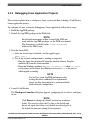
The wizard closes. A browser starts and displays the Documentation page. This
page contains tabs that group the CodeWarrior documentation into categories.
CodeWarrior Development Studio for Power Architecture Processors Getting Started Guide, Rev. 10.5.0,
06/2015
6
Freescale Semiconductor, Inc.
Chapter 1 Introduction
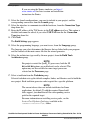
Figure 1-1. Documentation Page
NOTE
Click any tab in the Documentation page to browse the
CodeWarrior documentation.
You have successfully installed CodeWarrior Development Studio.
NOTE
For licensing and activation of your CodeWarrior Development
Studio for Power Architecture Processors, see CodeWarrior
Development Suite Quick Start. Save the license file,
license.dat, to the installation root folder; the default location is
<CodeWarrior-Install-Dir>\PA, where <CodeWarrior-Install-Dir>
is the path to your CodeWarrior installation.
1.3 Supported Devices
CodeWarrior Development Studio for Power Architecture Processors Getting Started Guide, Rev. 10.5.0,
06/2015
Freescale Semiconductor, Inc.
7
Supported Devices
This section talks about the device families and targets supported by CodeWarrior
Developer Studio for Power® Architecture Processors.
Table 1-2. Supported Device Families and Targets
Device Family
Supported Targets
82xx
Supports generation of 8250 target projects.
83xx
Supports generation of 8306, 8309, 8377 target projects.
85xx
Supports generation of 8536, 8548, 8560, 8568, 8569, 8572 target projects.
C29x
Supports generation of C29x target projects.
Qonverge
Supports generation of B4420, B4460, B4860, BSC9131, BSC9132, G1110, G4860
target projects.
QorIQ_P1
Supports generation of P1010, P1011, P1012, P1013, P1014, P1015, P1016, P1017,
P1020, P1021, P1022, P1023, P1024, P1025 target projects.
QorIQ_P2
Supports generation of P2010, P2020, P2040, P2041 target projects.
QorIQ_P3
Supports generation of P3041 target projects.
QorIQ_P4
Supports generation of P4040, P4080 target projects.
QorIQ_P5
Supports generation of P5010, P5020, P5021, P5040 target projects.
QorIQ_T1
Supports generation of T1013, T1014, T1020, T1022, T1023, T1024, T1040, T1042
target projects.
QorIQ_T2
Supports generation of T2080, T2081 target projects.
QorIQ_T4
Supports generation of T4160, T4240 target projects.
CodeWarrior Development Studio for Power Architecture Processors Getting Started Guide, Rev. 10.5.0,
06/2015
8
Freescale Semiconductor, Inc.
Chapter 2
Configuring Target Hardware
This chapter explains how to configure the boards supported by the CodeWarrior
Developer Studio for Power® Architecture Processors. You can configure these boards
using an integrated development environment (IDE), such as Freescale's CodeWarrior
IDE.
This chapter contains these topics:
•
•
•
•
•
Configuring B4420 QDS Board
Configuring B4860 QDS Board
Configuring P4080DS Board
Configuring BSC9131/G1110 RDB Board
Configuring BSC9132 QDS Board
2.1 Configuring B4420 QDS Board
This section describes the configuration of a B4420 QDS board.
Perform the following steps to configure a B4420 QDS board:
1. Ensure that the board is not connected to the power.
2. Ensure that the power to the chassis or the standalone power supply is OFF.
NOTE
It is recommended that you wear a wrist strap before
handling the B4420 QDS board to protect the board from
electrical charges.
3. Check the default switch positions and jumper settings and verify if the board is
operational.
CodeWarrior Development Studio for Power Architecture Processors Getting Started Guide, Rev. 10.5.0,
06/2015
Freescale Semiconductor, Inc.
9
Configuring B4860 QDS Board
NOTE
The board is shipped with default settings. See the
document shipped with the board to verify the default
switch and jumper settings.
4. Assemble the power supply.
a. Ensure that all power is turned OFF.
b. Connect the power supply, power cable, and country-specific wall outlet plug.
c. Connect the power-supply cable to the 12-volt board jack.
d. Plug power supply cable into the wall outlet.
5. Perform an initial board check and look for correct LED functioning.
6. Move the power switch to the ON position.
7. Check for completion of the PRESET (Power-on-Reset) sequence indicated by the
LEDs.
8. Move the power switch to the OFF position to power off the system.
NOTE
For more information, see the documentation shipped with
the B4420 QDS board.
2.2 Configuring B4860 QDS Board
This section tells how to configure a B4860 QDS board.
Perform the following steps to configure a B4860 QDS board:
1. Ensure that board is not connected to the power.
2. Ensure that the power to the chassis or the standalone power supply is OFF.
NOTE
It is recommended that you wear a wrist strap before
handling the B4860 QDS board to protect the board from
electrical charges.
CodeWarrior Development Studio for Power Architecture Processors Getting Started Guide, Rev. 10.5.0,
06/2015
10
Freescale Semiconductor, Inc.
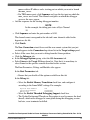
Chapter 2 Configuring Target Hardware
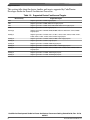
Figure 2-1. B4860 QDS Board
3. Check the default switch positions and jumper settings and verify if the board is
operational.
NOTE
The board is shipped with default settings. See Quick Start
Guide for B4860QDS to verify the default switch and
jumper settings.
4. Assemble the power supply.
a. Ensure that all power is turned OFF.
b. Connect the power supply, power cable, and country-specific wall outlet plug.
c. Connect the power-supply cable to the 12-volt board jack (P2).
d. Connect the USB cable between the B4860 QDS USB socket (J2) and the USB
port of the PC.
This setting relates to the internal debug probe, eCWTAP usage.
e. Connect an ETH cable between a network plug and the RJ-45 eCWTAP (J16)
jack.
f. Connect a second ETH cable between a network plug and the RJ-45GE1 (J18)
jack.
CodeWarrior Development Studio for Power Architecture Processors Getting Started Guide, Rev. 10.5.0,
06/2015
Freescale Semiconductor, Inc.
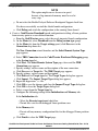
11
Configuring P4080DS Board
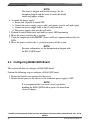
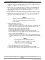
Figure 2-2. Connecting the B4860 QDS Board
g. Plug power supply cable into the wall outlet.
5. Perform an initial board check and look for correct LED functioning.
a. LED LD9 and LED LD10 are a steady green color.
b. LED D1 (eCWTAP) flashes orange and if the CodeWarrior TAP establishes a
link via the Ethernet, D1 changes to a steady green color, after several seconds of
charging.
6. Move the power switch (SW6) to the ON position.
7. Check for completion of the PRESET (Power-on-Reset) sequence indicated by the
LEDs. The LEDs on the board follow the below sequence:
a. LED LD1 and LED LD2 flash green.
b. LED LD8 (12 V) displays steady green light indicating that the SoC has exited
reset and is now in a Ready state.
NOTE
Some RCW combinations can change SOC ASLEEP
signal functionality to GPIO. In this case, LED LD8
enters an OFF state following the reset sequence.
8. Move the power switch (SW6) to the OFF position to power off the system.
NOTE
See Quick Start Guide for B4860QDS for more information
about the B4860 QDS board.
2.3 Configuring P4080DS Board
CodeWarrior Development Studio for Power Architecture Processors Getting Started Guide, Rev. 10.5.0,
06/2015
12
Freescale Semiconductor, Inc.
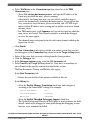
Chapter 2 Configuring Target Hardware
This section explains how to configure a P4080DS board.
Perform the following steps to configure a P4080DS board:
1. Power off the P4080DS desktop development system.
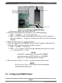
Figure 2-3. P4080DS Desktop Development System
2. Disconnect the development system from the power.
NOTE
It is recommended that you wear a wrist strap before
handling the P4080DS board to protect the board from
electrical charges.
3. Connect a serial cable:
a. Connect one end of a serial cable to your PC.
b. Connect the other end to the DB9 serial connector on the back of the
development system. Use the connector farthest from the fan.
4. Connect the CodeWarrior TAP (over USB).
NOTE
For more details on using an Ethernet TAP or a Gigabit
TAP, see Ethernet TAP Quick Start or Gigabit TAP Users
Guide available in the <CodeWarrior-Install-Dir>\PA\Help\PDF
folder.
a. Remove the development system's cover to expose the P4080DS board.
CodeWarrior Development Studio for Power Architecture Processors Getting Started Guide, Rev. 10.5.0,
06/2015
Freescale Semiconductor, Inc.
13
Configuring BSC9131/G1110 RDB Board
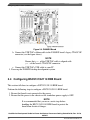
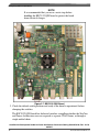
Figure 2-4. P4080DS Board
b. Connect the USB TAP's ribbon cable to the P4080DS board's legacy JTAG/COP
connector (see the figure above).
NOTE
Ensure that pin 1 of the USB TAP cable is aligned with
pin 1 of the board's JTAG/COP connector.
c. Connect the USB TAP's USB cable to your PC.
5. Power up the P4080DS desktop development system.
2.4 Configuring BSC9131/G1110 RDB Board
This section tells how to configure a BSC9131/G1110 RDB board.
Perform the following steps to configure a BSC9131/G1110 RDB board:
1. Ensure that board is not connected to the power.
2. Ensure that the power to the chassis or the standalone power supply is OFF.
NOTE
It is recommended that you wear a wrist strap before
handling the BSC9131/G1110 RDB board to protect the
board from electrical charges.
CodeWarrior Development Studio for Power Architecture Processors Getting Started Guide, Rev. 10.5.0,
06/2015
14
Freescale Semiconductor, Inc.
Chapter 2 Configuring Target Hardware
Figure 2-5. BSC9131/G1110 RDB Board
3. Check the default switch positions and verify if the board is operational, before
changing the switches.
The BSC9131 RDB board has dedicated switches controlling the JTAG topology
configuration, irrespective of whether the StarCore and Power Architecture TAPs are
daisy chained or accessed separately from the JTAG ports.
• For the dual TAP mode on Power Architecture JTAG port (the Power
Architecture TAP and DSP TAP are daisy chained and accessed from the Power
CodeWarrior Development Studio for Power Architecture Processors Getting Started Guide, Rev. 10.5.0,
06/2015
Freescale Semiconductor, Inc.
15
Configuring BSC9131/G1110 RDB Board
Architecture JTAG port; the DSP JTAG port is not used), set the on-board dip
switch SW6[3:4] to ON/ON (CFG_JTAG_MODE[0:1] = 00).
• For the single TAP mode through primary JTAG header (Power Architecture
TAP is accessed from the Power Architecture JTAG port; the DSP TAP and
DSP JTAG port are not used), set the on-board dip switch SW6[3:4] to OFF/ON
(CFG_JTAG_MODE[0:1] = 10).
• For the single TAP per JTAG port mode (Power Architecture TAP is accessed
from the Power Architecture JTAG port, DSP TAP is accessed from the DSP
JTAG port), set the on-board dip switch SW6[3:4] to OFF/OFF (CFG_JTAG_MODE[0:1] =
11).
NOTE
See BSC9131/G1110 RDB Hardware Getting Started
Guide to learn how to specify the switches and jumper
header settings.
• Assemble and connect the board.
1. Ensure that all power is turned off.
2. Connect 12-volt power supply, power cable, and country-specific wall plug.
3. Connect the power-supply jack cable to the board power connector P5.
4. Plug power supply into the surge-protected strip.
5. Connect the surge-protected strip to the AC outlet.
6. Connect dual RS-232 to single DIL 10-pin cable to connector J18.
7. Connect R232 9-pin cable to COM1 cable end. Note that the R232 9-pin
cable is not included in hardware kit.
8. Connect the CodeWarrior TAP (over USB) to your development machine
and to the JTAG/COP 16-pin connector (J16) of the BSC9131/G1110 RDB
board.
NOTE
For more details on using an Ethernet TAP or a
Gigabit TAP, see Ethernet TAP Quick Start or the
Gigabit TAP Users Guide available in the
<CodeWarrior-Install-Dir>\PA\Help\PDF folder.
9. Move the power switch (S1) to the ON position.
10. Check for completion of the reset sequence indicated by the LEDs.
11. Move the power switch (S1) to the OFF position to power off the system.
CodeWarrior Development Studio for Power Architecture Processors Getting Started Guide, Rev. 10.5.0,
06/2015
16
Freescale Semiconductor, Inc.
Chapter 2 Configuring Target Hardware
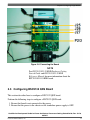
Figure 2-6. Connecting the Board
NOTE
See BSC9131/G1110 RDB Hardware Getting
Started Guide and BSC9131/G1110 RDB
Reference Manual for more information about the
BSC9131/G1110 RDB board.
2.5 Configuring BSC9132 QDS Board
This section describes how to configure a BSC9132 QDS board.
Perform the following steps to configure a BSC9132 QDS board:
1. Ensure that board is not connected to the power.
2. Ensure that the power to the chassis or the standalone power supply is OFF.
CodeWarrior Development Studio for Power Architecture Processors Getting Started Guide, Rev. 10.5.0,
06/2015
Freescale Semiconductor, Inc.
17
Configuring BSC9132 QDS Board
NOTE
It is recommended that you wear a wrist strap before
handling the BSC9132 QDS board to protect the board
from electrical charges.
Figure 2-7. BSC9132 QDS Board
3. Check the default switch positions and verify if the board is operational, before
changing the switches.
The BSC9132 QDS board has dedicated switches controlling whether the StarCore
and Power Architecture cores are exposed as separate JTAG chains, or through a
single unified chain.
CodeWarrior Development Studio for Power Architecture Processors Getting Started Guide, Rev. 10.5.0,
06/2015
18
Freescale Semiconductor, Inc.
Chapter 2 Configuring Target Hardware
• For a single unified JTAG chain, set the on-board dip switch SW10[7:8] to ON/ON
(CFG_JTAG_MODE_0:1 = 00). The JTAG connector will be J3 (COP HEADER).
• For single TAP mode through primary JTAG header (J3, COP Header), set the onboard dip switch SW10[7:8] to ON/OFF (CFG_JTAG_MODE_0:1 = 01).
• For single TAP mode through secondary JTAG header (J2, ONCE Header), set the
on-board dip switch SW10[7:8] to OFF/OFF (CFG_JTAG_MODE_0:1 = 11).
NOTE
See BSC9132QDS Hardware Getting Started Guide
document to learn how to specify the switches and
jumper header settings.
• Assemble and connect the board.
1. Ensure that all power is turned off.
2. Connect 12-volt power supply, power cable, and country-specific wall plug.
3. Connect the power-supply jack cable to the board power connector P4.
4. Plug power supply into the surge-protected strip.
5. Connect the surge-protected strip to the AC outlet.
6. Connect R232 9-pin cable to connector J25, if you intend to use an UART
connection.
CodeWarrior Development Studio for Power Architecture Processors Getting Started Guide, Rev. 10.5.0,
06/2015
Freescale Semiconductor, Inc.
19
Configuring BSC9132 QDS Board
7. Connect R232 9-pin cable to COM1 cable end. Note that the R232 9-pin
cable is not included in hardware kit.
8. Connect the CodeWarrior TAP (over USB) to your development machine
and to the JTAG/COP (J3, 16-pin) or JTAG/ONCE (J2, 14-pin) of the
BSC9132 QDS board, depending on selection from SW10[7:8].
NOTE
If you are using an Ethernet TAP, see Ethernet
TAP Quick Start available in the <CodeWarriorInstall-Dir>\PA\ folder for set up instructions.
9. Move the power switch to the ON position.
10. Check for completion of the reset sequence indicated by the LEDs.
11. Move the power switch to the OFF position to power off the system.
NOTE
See BSC9132QDS Hardware Getting Started
Guide and BSC9132QDS Reference Manual for
more information about the BSC9132 QDS board.
CodeWarrior Development Studio for Power Architecture Processors Getting Started Guide, Rev. 10.5.0,
06/2015
20
Freescale Semiconductor, Inc.
Chapter 3
Working with Projects
This chapter explains how to use CodeWarrior tools to create and work with projects.
NOTE
The scope of this chapter is limited to the use of the
CodeWarrior IDE to write and debug applications for the target
platform.
This chapter explains:
•
•
•
•
•
Launching CodeWarrior IDE
Creating Projects
Building Projects
Debugging Projects
Deleting a Project
3.1 Launching CodeWarrior IDE
This section provides the steps required to launch CodeWarrior IDE.
To launch the CodeWarrior IDE, perform these steps:
1. Select Start > All Programs > Freescale CodeWarrior > CW for Power
Architecture vnumber > CodeWarrior IDE, where number is the version number
of your product.
The Workspace Launcher dialog box appears, prompting you to select a workspace
to use.
CodeWarrior Development Studio for Power Architecture Processors Getting Started Guide, Rev. 10.5.0,
06/2015
Freescale Semiconductor, Inc.
21
Creating Projects
NOTE
Click Browse to change the default location for workspace
folder. You can also select the Use this as the default and
do not ask again checkbox to set default or selected path
as the default location for storing all your projects.
2. Click OK.
The default workspace is accepted. The CodeWarrior IDE launches and the
Welcome page appears.
NOTE
The Welcome page appears only if the CodeWarrior IDE
or the selected workspace is opened for the first time.
Otherwise, the Workbench window appears.
3. Click Go to Workbench, on the Welcome page.
The Workbench window appears.
The CodeWarrior IDE is ready for use. You can now create, build, debug, or customize
your project to match your requirements.
3.2 Creating Projects
This section explains how to use the CodeWarrior Bareboard Project Wizard and the
CodeWarrior Linux Project Wizard to quickly create new projects with default settings
(build and launch configurations).
After the project has been created, you can easily change any default setting to suit your
needs.
NOTE
For detailed information on various wizard options, see
CodeWarrior Development Studio for Power Architecture
Processors Targeting Manual.
In this section:
• Creating CodeWarrior Bareboard Application Project
• Creating CodeWarrior Bareboard Library Project
• Creating CodeWarrior Linux Application Project
CodeWarrior Development Studio for Power Architecture Processors Getting Started Guide, Rev. 10.5.0,
06/2015
22
Freescale Semiconductor, Inc.
Chapter 3 Working with Projects
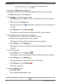
3.2.1 Creating CodeWarrior Bareboard Application Project
You can create a CodeWarrior bareboard application project using the CodeWarrior
Bareboard Project Wizard.
To create a CodeWarrior bareboard application project, perform the following steps:
1. Launch the CodeWarrior IDE. For details, see Launching CodeWarrior IDE.
2. Select File > New > CodeWarrior Bareboard Project Wizard from the
CodeWarrior IDE menu bar.
The CodeWarrior Bareboard Project Wizard launches and the Create a
CodeWarrior Bareboard Project page appears.
3. Specify a name for the new project in the Project name text box.
For example, enter the project name as application_project.
4. If you do not want to create your project in the default workspace:
a. Clear the Use default location check box.
b. Click Browse and select the desired location for your project from the Browse
For Folder dialog box.
The selected location gets added to the Location text box.
5. Click Next.
The Processor page appears.
6. Select the target processor for the new project from the Processor list.
7. Select Application from the Project Output group, to create an application
with .elf extension that includes information required to debug the project.
8. Click Next.
The Debug Target Settings page appears.
9. Select a supported connection type (hardware, simulator, or emulator), from the
Debugger Connection Types group. Your selection determines the launch
configurations that you can include in your project.
10. Select the board you are targeting, from the Board drop-down list.
NOTE
Hardware or simulators that support the target processor
selected on the Processors page are only available for
selection.
CodeWarrior Development Studio for Power Architecture Processors Getting Started Guide, Rev. 10.5.0,
06/2015
Freescale Semiconductor, Inc.
23
Creating Projects
If you are using the Simics simulator, see https://
www.simics.net/ for latest version and installation
instructions for Simics.
11. Select the launch configurations, you want to include in your project, and the
corresponding connection, from the Launch group.
12. Select the interface to communicate with the hardware, from the Connection Type
drop-down list.
13. Enter the IP address of the TAP device in the TAP address text box. This option is
disabled and cannot be edited, if you select USB TAP from the the Connection
Type drop-down list.
14. Click Next.
The Build Settings page appears.
15. Select the programming language, you want to use, from the Language group.
The language you select determines the libraries that are linked with your program
and the contents of the main source file that the wizard generates.
16. Select the architecture type used by the new project, from the Build Tools
Architecture group.
NOTE
For projects created for QorIQ_P5 processors, both the 32
bit and 64 bit options are enabled and can be selected. This
option may not be available for some target processors
selected on the Processors page.
17. Select a toolchain from the Toolchain group.
Selected toolchain sets up the default compiler, linker, and libraries used to build the
new project. Each toolchain generates code targeted for a specific platform.
NOTE
The current release does not include toolchains for Linux
applications, by default. To add the required Linux build
tools support, you should install the corresponding service
pack for the required target.
For more information on installing service packs, see the
Service Pack Updater Quickstart available in the
<CodeWarrior-Install-Dir>\PA\ folder.
CodeWarrior Development Studio for Power Architecture Processors Getting Started Guide, Rev. 10.5.0,
06/2015
24
Freescale Semiconductor, Inc.
Chapter 3 Working with Projects
18. Select an option from the Floating Point drop-down list, to prompt the compiler to
handle the floating-point operations by generating instructions for the selected
floating-point unit.
19. Click Next.
The Configurations page appears.
20. Select a processing model option from the Processing Model group.
NOTE
The SMP option is available for selection only while
creating projects for some e500mc, e5500, and e6500 core
targets.
• Select SMP (one build configuration for all the cores) to generate a single
project for all the cores.
• Select AMP (One project per core) to generate a separate project for each
selected core. The option will also set the core index for each project based on
the core selection.
• Select AMP (One build configuration per core) to generate one project with
multiple targets, each containing an .lcf file for the specified core.
NOTE
Selecting the AMP (One build configuration per
core) option displays a check box, Set up build
references for build configurations of all cores, just
below this option. If you select the Set up build
references for build configurations of all cores check
box, then building the project for one core will
automatically build the project for other cores as well.
If you do not select this check box, then you would
need to manually build the project for each core.
21. Select the processor core that executes the project, from the Core index list.
22. Click Next.
The Trace Configuration page appears.
23. If you plan to collect the trace details:
a. Select the Start a trace session on debug launch check box, to start a trace
session automatically on debug launch.
b. Select the source used for collecting trace data, from the Generate trace
configurations group.
• Select the DDR Buffer check box, to send the trace data to a DDR memory
buffer.
CodeWarrior Development Studio for Power Architecture Processors Getting Started Guide, Rev. 10.5.0,
06/2015
Freescale Semiconductor, Inc.
25
Creating Projects
• Select the NPC Buffer check box, to send the trace data to a small dedicated
trace buffer.
• Select the Gigabit TAP + Trace check box, to collect trace data on a
Gigabit Tap + Trace probe.
c. Select the Enable circular collection check box, from the Enable circular
collection (DDR and NPC only) group, to treat the trace buffer as a 'circular
buffer.' Selection of this check box ensures continuation of trace collection, even
after the buffer is full, by replacing the older entries.
24. Click Finish.
The wizard creates an application project according to your specifications. You can
access the project from the CodeWarrior Projects view on the workbench.
The new project is ready for use. You can now customize the project by adding your own
source code files, changing debugger settings, and adding libraries.
3.2.2 Creating CodeWarrior Bareboard Library Project
You can create a CodeWarrior bareboard library project using the CodeWarrior
Bareboard Project Wizard.
To create a CodeWarrior bareboard library project, perform the following steps:
1. Launch the CodeWarrior IDE. For details, see Launching CodeWarrior IDE.
2. Select File > New > CodeWarrior Bareboard Project Wizard from the
CodeWarrior IDE menu bar.
The CodeWarrior Bareboard Project Wizard launches and the Create a
CodeWarrior Bareboard Project page appears.
3. Specify a name for the new project in the Project name text box.
For example, enter the project name as library_project.
4. If you do not want to create your project in the default workspace:
a. Clear the Use default location check box.
b. Click Browse and select the desired location for your project from the Browse
For Folder dialog box.
The selected location gets added to the Location text box.
5. Click Next.
CodeWarrior Development Studio for Power Architecture Processors Getting Started Guide, Rev. 10.5.0,
06/2015
26
Freescale Semiconductor, Inc.
Chapter 3 Working with Projects
The Processor page appears.
6. Select the target processor for the new project from the Processor list.
7. Select Static Library from the Project Output group, to create a library with .a
extension that can be included in other projects. Library files created using this
option do not include board specific details.
8. Click Next.
The Build Settings page appears.
9. Select the programming language, you want to use, from the Language group.
The language you select determines the libraries that are linked with your program
and the contents of the main source file that the wizard generates.
10. Select a toolchain from the Toolchain group.
Selected toolchain sets up the default compiler, linker, and libraries used to build the
new project. Each toolchain generates code targeted for a specific platform.
NOTE
The current release does not include toolchains for Linux
applications, by default. To add the required Linux build
tools support, you should install the corresponding service
pack for the required target.
For more information on installing service packs, see the
Service Pack Updater Quickstart available in the
<CodeWarrior-Install-Dir>\PA\ folder.
11. Select an option from the Floating Point drop-down list, to prompt the compiler to
handle the floating-point operations by generating instructions for the selected
floating-point unit.
12. Click Finish.
The wizard creates a library project according to your specifications. You can access
the project from the CodeWarrior Projects view on the workbench.
The new library project is ready for use. You can now customize the project to match
your requirements.
3.2.3 Creating CodeWarrior Linux Application Project
CodeWarrior Development Studio for Power Architecture Processors Getting Started Guide, Rev. 10.5.0,
06/2015
Freescale Semiconductor, Inc.
27
Creating Projects
You can create a CodeWarrior Linux application project using the CodeWarrior Linux
Project Wizard.
To create a CodeWarrior Linux application project, perform the following steps:
1. Launch the CodeWarrior IDE. For details, see Launching CodeWarrior IDE.
2. Select File > New > CodeWarrior Linux Project Wizard from the CodeWarrior
IDE menu bar.
The CodeWarrior Linux Project Wizard launches and the Create a CodeWarrior
Linux Project page appears.
3. Specify a name for the new project in the Project name text box.
For example, enter the project name as linux_application_project.
4. If you do not want to create your project in the default workspace:
a. Clear the Use default location check box.
b. Click Browse and select the desired location for your project from the Browse
For Folder dialog box.
The selected location gets added to the Location text box.
5. Click Next.
The Processor page appears.
6. Select the target processor for the new project from the Processor list.
7. Select Application from the Project Output group, to create an application
with .elf extension that includes information required to debug the project.
8. Click Next.
The Build Settings page appears.
9. Select a toolchain from the Toolchain group.
Selected toolchain sets up the default compiler, linker, and libraries used to build the
new project. Each toolchain generates code targeted for a specific platform.
NOTE
The current release does not include toolchains for Linux
applications, by default. To add the required Linux build
tools support, you should install the corresponding service
pack for the required target.
CodeWarrior Development Studio for Power Architecture Processors Getting Started Guide, Rev. 10.5.0,
06/2015
28
Freescale Semiconductor, Inc.
Chapter 3 Working with Projects
For more information on installing service packs, see the
Service Pack Updater Quickstart available in the
<CodeWarrior-Install-Dir>\PA\ folder.
10. Select the programming language, you want to use, from the Language group.
The language you select determines the libraries that are linked with your program
and the contents of the main source file that the wizard generates.
11. Select the architecture type used by the new project, from the Build Tools
Architecture group.
NOTE
For projects created for QorIQ_P5 processors, both the 32
bit and 64 bit options are enabled and can be selected. This
option may not be available for some target processors
selected on the Processors page.
12. Click Next.
The Linux Application page appears.
13. Select CodeWarrior TRK to use the CodeWarrior Target Resident Kernel (TRK)
protocol, to download and control application on the Linux host system.
NOTE
When debugging a Linux application, you must use the
CodeWarrior TRK to manage the communication interface
between the debugger and Linux system.
14. Specify a Remote System Configuration option.
15. In the IP Address text box, enter the IP Address of the Linux host system, the
project executes on.
16. In the Port text box, enter the port number that the debugger will use to
communicate to the Linux host system.
17. In the Remote Download Path text box, enter the absolute path for the host
directory, into which the debugger downloads the application.
18. Click Finish.
The wizard creates a Linux application project according to your specifications. You
can access the project from the CodeWarrior Projects view on the workbench.
The new CodeWarrior Linux application project is ready for use. You can now customize
the project to match your requirements.
CodeWarrior Development Studio for Power Architecture Processors Getting Started Guide, Rev. 10.5.0,
06/2015
Freescale Semiconductor, Inc.
29
Building Projects
3.3 Building Projects
CodeWarrior IDE supports two modes of building projects, manual-build mode and autobuild mode.
3.3.1 Manual-Build Mode
In large workspaces, building the entire workspace can take a long time if users make
changes with a significant impact on the dependent projects. Often there are only a few
projects that really matter to a user at a given time.
To build only the selected projects, and any prerequisite projects that need to be built in
order to correctly build the selected projects, select Project > Build Project from the
CodeWarrior IDE menu bar. Alternatively, select Project > Build All.
Tip
You can also right-click on the selected project in the
CodeWarrior Projects view and select Build Project from the
context menu.
3.3.2 Auto-Build Mode
CodeWarrior IDE takes care of compiling source files automatically. Builds occur
automatically in the background every time you change files in the workspace (for
example, saving an editor), if auto-build is enabled.
To automatically build all the projects in a workspace, select Project > Build
Automatically from the CodeWarrior IDE menu bar.
If auto-build is taking too long and is interfering with ongoing development, it can be
turned off. Select Project > Build Automatically from the CodeWarrior IDE menu bar
to disable auto-build mode.
NOTE
It is advised that you do not use the Build Automatically
option for C/C++ development. Using this option will result in
CodeWarrior Development Studio for Power Architecture Processors Getting Started Guide, Rev. 10.5.0,
06/2015
30
Freescale Semiconductor, Inc.
Chapter 3 Working with Projects
building the entire project whenever you save a change to the
makefile or source files. This can take a significant amount of
time for very large projects.
3.4 Debugging Projects
This section explains how to use the CodeWarrior development tools to debug both
bareboard and embedded Linux® software for Power® Architecture processors.
•
•
•
•
•
Debugging Bareboard Application Projects
Debugging Linux Application Projects
Debugging Guest LWEs Using Hypervisor
Debugging Guest Linux Kernels Using Hypervisor
Debugging U-Boot
3.4.1 Debugging Bareboard Application Projects
This section explains how to change the debugger settings and how to debug a
CodeWarrior bareboard application project.
The CodeWarrior Bareboard Project wizard sets the debugger settings of the project's
launch configurations to default values. You can change these default values based on
your requirements.
To modify the debugger settings and start debugging a CodeWarrior project, perform
these steps:
1. Launch the CodeWarrior IDE.
2. From the CodeWarrior IDE menu bar, select Run > Debug Configurations. The
CodeWarrior IDE uses the settings in the launch configuration to generate debugging
information and initiate communication with the target board.
The Debug Configurations dialog box appears. The left side of this dialog box has a
list of debug configurations that apply to the current application.
NOTE
For more information on how to use the debugger, see
CodeWarrior Development Studio Common Features
Guide and CodeWarrior Development Studio for Power
CodeWarrior Development Studio for Power Architecture Processors Getting Started Guide, Rev. 10.5.0,
06/2015
Freescale Semiconductor, Inc.
31
Debugging Projects
Architecture Processors Targeting Manual available in the
<CodeWarrior-Install-Dir>\PA\ folder.
3. Expand the CodeWarrior configuration.
4. From the expanded list, select the debug configuration that you want to modify.
The Main page appears in the right panel.
5. Click Debug to start the debugging session.
a. The Debug perspective appears and the execution halts at the first statement of
main().
b. Click a thread in the Debug view.
The program counter icon
executed.
on the marker bar points to the next statement to be
c. In the Debug view, click Step Over
.
The debugger executes the current statement and halts at next statement.
6. Set breakpoint and execute program to breakpoint.
a. In the editor area, scroll to a line of command statement.
b. Double-click the marker bar next to the statement.
The breakpoint indicator (blue dot) appears next to the statement.
c. In the Debug view, click Resume
.
The debugger executes all statements up to but not including the breakpoint
statement.
7. Control the program:
a. In the Debug view, click Step Over
.
The debugger executes the breakpoint statement and halts at the next statement.
b. In the Debug view, click Resume
.
The program outputs to the Console window at the bottom.
c. In the Debug view, click Terminate
.
The debug session ends.
8. Close the Console window:
a. Select File > Exit.
The CodeWarrior IDE window closes.
CodeWarrior Development Studio for Power Architecture Processors Getting Started Guide, Rev. 10.5.0,
06/2015
32
Freescale Semiconductor, Inc.
Chapter 3 Working with Projects
3.4.2 Debugging Linux Application Projects
This section explains how to configure a Linux system and how to debug a CodeWarrior
Linux application project.
To configure a Linux system for debugging a Linux application, follow these steps:
1. Build the AppTRK package.
2. Include the AppTRK package in the RAM disk.
NOTE
For detailed instructions on how to install the SDK and
work with the AppTRK package, see the SDK user manual.
The document is available in the iso/help/documents/pdf
folder of the SDK layout.
3. Start the Linux BSP:
a. After the kernel boot is finished, start the apptrk agent
apptrk :12345 &
b. Test if the network configuration is working as expected:
• Ping the Linux host machine IP from the simulated Linux. Ping the
simulated IP from the Linux machine.
• From the Windows machine, try telnet <IP address> 1234 where <IP address>
is the address of the Linux alias Ethernet device and 1234 is the port on
which apptrk is running.
NOTE
You will see some AppTRK information after
issuing the telnet command. If no information
shows up, then there might be a problem with the
whole network configuration.
4. Launch CodeWarrior.
The Workspace Launcher dialog box appears, prompting you to select a workspace
to use.
NOTE
Click Browse to change the default location for workspace
folder. You can also select the Use this as the default and
do not ask again check box to set default or selected path as
the default location for storing all your projects.
CodeWarrior Development Studio for Power Architecture Processors Getting Started Guide, Rev. 10.5.0,
06/2015
Freescale Semiconductor, Inc.
33
Debugging Projects
5. Click OK.
The default workspace is accepted.
6. Select File > New > CodeWarrior Linux Project Wizard, from the CodeWarrior
IDE menu bar.
The CodeWarrior Linux Project Wizard launches and the Create a CodeWarrior
Linux Project page appears.
7. Specify a name for the new project in the Project name text box.
For example, enter the project name as linux_project.
8. If you do not want to create your project in the default workspace:
a. Clear the Use default location check box.
b. Click Browse and select the desired location from the Browse For Folder
dialog box.
c. In the Location text box, append the location with the name of the directory in
which you want to create your project.
NOTE
An existing directory cannot be specified for the
project location.
9. Click Next.
The Processor page appears.
10. Select the target processor for the new project, from the Processor list.
11. Select Application from the Project Output group, to create an application
with .elf extension that includes information required to debug the project.
12. Click Next.
The Build Settings page appears.
13. Select a toolchain for Linux applications from the Toolchain group.
Selected toolchain sets up the default compiler, linker, and libraries used to build the
new project. Each toolchain generates code targeted for a specific platform.
NOTE
The current release does not include toolchains for Linux
applications, by default. To add the required Linux build
tools support, you should install the corresponding service
pack for the required target.
CodeWarrior Development Studio for Power Architecture Processors Getting Started Guide, Rev. 10.5.0,
06/2015
34
Freescale Semiconductor, Inc.
Chapter 3 Working with Projects
For more information on installing service packs, see the
Service Pack Updater Quickstart available in the
<CodeWarrior-Install-Dir>\PA\ folder.
14. Select the programming language, you want to use, from the Language group.
The language you select determines the libraries that are linked with your program
and the contents of the main source file that the wizard generates.
15. Select the architecture type used by the new project, from the Build Tools
Architecture group.
16. Click Next.
The Linux Application page appears.
17. Select CodeWarrior TRK to use the CodeWarrior Target Resident Kernel (TRK)
protocol, to download and control application on the Linux host system.
NOTE
When debugging a Linux application, you must use the
CodeWarrior TRK to manage the communications interface
between the debugger and Linux system.
18. Specify a Remote System Configuration option.
19. In the IP Address text box, enter the IP Address of the Linux host system, the
project executes on.
20. In the Port text box, enter the port number that the debugger will use to
communicate to the Linux host system.
21. In the Remote Download Path text box, enter the absolute path for the host
directory, into which the debugger downloads the application.
22. Click Finish.
The wizard creates a Linux application project according to your specifications. You
can access the project from the CodeWarrior Projects view on the workbench.
23. From the CodeWarrior IDE menu bar, select Run > Debug Configurations.
The Debug Configurations dialog box appears. The left side of this dialog box has a
list of debug configurations that apply to the current application.
24. Expand the CodeWarrior configuration.
25. From the expanded list, select the debug configuration that you want to modify.
The Main page appears in the right pane.
CodeWarrior Development Studio for Power Architecture Processors Getting Started Guide, Rev. 10.5.0,
06/2015
Freescale Semiconductor, Inc.
35
Debugging Projects
26. Edit the AppTRK connection to the address of the auxiliary Ethernet adapter from
the Linux machine.
27. Click Debug to debug the Linux application project.
The Debug perspective appears with the control stopped at main().
3.4.3 Debugging Guest LWEs Using Hypervisor
This section describes how to configure and build hypervisor support on a Linux machine
and debug bareboard applications using hypervisor.
The steps are given below:
1. Compile the embedded-hv package. The package should be compiled with
HyperTRK enabled.
NOTE
See the SDK user manual for instructions on how to install
the SDK and work with the HyperTRK. The document is
available in the iso/help/documents/pdf folder of the SDK
layout.
2. Configure HyperTRK debug support in the Hypervisor Device Tree.
a. In the hypervisor configuration file (the .dts file), ensure that a muxer device is
defined and is connected to a physical UART. For example, see the listing
below:
Listing 3-1. Defining and connecting a muxer device
uartmux: uartmux {
compatible = "byte-channel-mux";
endpoint = <&serial0>;
};
b. Identify the partition for which you want to add the HyperTRK debug support. A
HyperTRK stub DTS entry must be added for each virtual CPU you want to
debug. Listing below shows an example of how you identify the partition to add
HyperTRK debug stub support.
Listing 3-2. Identifying the partition for adding debug support
// =====================================================
// Partition 1
// =====================================================
CodeWarrior Development Studio for Power Architecture Processors Getting Started Guide, Rev. 10.5.0,
06/2015
36
Freescale Semiconductor, Inc.
Chapter 3 Working with Projects
part1 {
// Indicates that it is a partition node
compatible = "partition";
label = "p1-linux";
// CPU #0 and #1 is assigned to this partition
cpus = <0 2>;
guest-image = <0xf 0xe8020000 0 0 0 0x00f00000>;
linux-rootfs = <0xf 0xe9300000 0 0x01300000 0 0x02800000>;
dtb-window = <0 0x1000000 0 0x12000>;
c. When using the Download debug session type, ensure that the debugged
partition does not have the no-auto-start option set in the device tree. After the
reset, the partition must be in the running state. In addition, comment any noauto-start options. For example:
// partition is not to be started by hypervisor.
// no-auto-start;
d. Compile the DTS file into a DTB file after adding the debug support. Ensure that
the DTC package was properly compiled and installed for the x86 Linux
machine, and that the dtc command is included in the PATH environment
variable.
dtc -p 1024 -O dtb hv_conf_source.dts -o hv_conf_new.dtb
The above command creates the new hv_conf_new.dtb file.
NOTE
For more detailed instructions, see CodeWarrior
Development Studio for Power Architecture
Processors Targeting Manual available in the
<CodeWarrior-Install-Dir>\PA\ folder.
e. Create a memory configuration file for the whole SMP LWE partition.
NOTE
For debugging any LWE application, create a memory
configuration file according to the MMU that the LWE
application uses. In addition, ensure that you create an
initial configuration file to be used for Download
launch configuration.You can create either one
memory configuration file for the whole SMP LWE
partition, or a single configuration file for each core
from the SMP partition.
1. Check the TLB entries for the partition you want to debug.
CodeWarrior Development Studio for Power Architecture Processors Getting Started Guide, Rev. 10.5.0,
06/2015
Freescale Semiconductor, Inc.
37
Debugging Projects
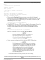
2. Pause the partition. For example, pause 3.
3. Display the guest tlb for a core, for example, gtlb
3 0,
and check TLB 1.
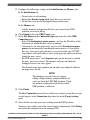
Figure 3-1. Guest TLB for a core
4. Observe that the first translation entry is not 1-1, 0x0c000000 ->
0x000100000. Therefore, add the following command in the memory
configuration file:
translate v:0x0c000000 p:0x00100000 0x00100000
Note that you do not need to add the translation entries that are already 1-1.
5. In case you find that TLB 0 also has non 1-1 translations and you want to
access the respective memory, go ahead and add the required translate
command in the memory configuration file.
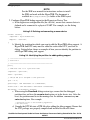
6. Display the guest tlb for another core, for example, gtlb 3 1, and check TLB
1.
Figure 3-2. TLB 1 for another core
7. Observe that the first translation entry is the same that you added in the
memory configuration file in the previous steps. In addition, observe the non
1-1 entry 0x01000000 -> 0x002000000. Note that this is the stack and is
present in other SMP secondary cores. However, in this case, instruct the
debugger to access the 0x01000000 - 0x01ffffff range by using virtual
addresses. For example:
CodeWarrior Development Studio for Power Architecture Processors Getting Started Guide, Rev. 10.5.0,
06/2015
38
Freescale Semiconductor, Inc.
Chapter 3 Working with Projects
range v:0x01000000 v:0x01ffffff 4 ReadWrite LogicalData
8. Follow the same procedure to access the 0x00300000 - 0x0030ffff range.
For example:
range v:0x00300000 v:0x0030ffff 4 ReadWrite LogicalData
9. Ensure that after checking the TLBs of all the cores, the required memory
configuration file looks like this:
AutoEnableTranslations
true
range v:0x0c000000 v:0x0c0fffff 4 ReadWrite LogicalData
range v:0x00300000 v:0x0030ffff 4 ReadWrite LogicalData
range v:0x01000000 v:0x01ffffff 4 ReadWrite LogicalData
NOTE
To create a memory configuration file per core for
the specific scenario described in this section,
replace the memory ranges on which you want the
debugger to access virtual memory with translated
sections from virtual to physical for these ranges,
as explained in previous steps for the first core,
gtlb 3 0.
f. Create an initial configuration file to be used for Download launch configuration.
1. Consider an LWE, hello.elf.
2. Run this command: readelf -h hello.elf.
The ELF header and the entry point address 0xc010000 are printed.
3. Having the MMU translation as 0x0c000000 - 0x0c0fffff 0x000100000 0x0001fffff and the entry point as 0xc010000, the initial configuration file
must contain alternatePC 0x110000 (the physical entry point of the
application).
g. Create a launch configuration to debug an LWE application:
1. Select File > Import to import the hello.elf LWE application. The Import
wizard launches and the Select page appears.
2. Expand the CodeWarrior group and select CodeWarrior Executable
Importer.
3. Click Next. The wizard name changes to Import a CodeWarrior
Executable file and the Import a CodeWarrior Executable file page
appears.
4. Specify a new project name.
5. Click Next. The Import C/C++/Assembler Executable Files page appears.
6. Select the executable vmlinux.elf built with -gdwarf from the images
directory.
7. Click Next. The Processor page appears.
8. Select a processor, toolchain, and target OS.
CodeWarrior Development Studio for Power Architecture Processors Getting Started Guide, Rev. 10.5.0,
06/2015
Freescale Semiconductor, Inc.
39
Debugging Projects
9. Click Next. The Debug Target Settings page appears.
10. Select a supported connection type from the Debugger Connection Types
group. Your selection determines the launch configurations that you can
include in your project.
11. Select the hardware or simulator, you plan to use, from the Board dropdown list.
12. Select the launch configurations, you want to include in your project, and the
corresponding connection.
13. Select the interface to communicate with the hardware, from the Connection
Type drop-down list.
14. Enter the IP address of the TAP device in the TAP address text box. This
option is disabled and cannot be edited, if you select USB TAP from the the
Connection Type drop-down list.
15. Click Next. The Configurations page appears.
16. Specify the core index for the project.
17. Click Finish. The Import a CodeWarrior Executable file wizard ends.
18. Select Run > Debug Configurations to open the Debug Configurations
dialog box.
h. Create a CodeWarrior Attach launch configuration.
1. From the CodeWarrior group, select the newly imported launch
configuration.
2. On the Main tab, select Attach from the Debug session type group.
3. On the Main tab, from the Target settings panel, click New next to the
Connection drop-down list.
The New Connection wizard launches and the Select Remote System Type
page appears.
4. Select TRK Connection from the CodeWarrior Bareboard Debugging
group in the System type list.
5. Click Next. The Select Remote System Type page closes and the TRK
Connection page appears.
6. Specify settings, such as name and description of the new connection.
7. Click New next to Target list. The TRK Target page appears.
8. Specify settings, such as name and description.
9. Click Edit next to Target type list. The Target Types dialog box appears.
10. Click Import. The Import Target Type dialog box appears.
11. Import the hypervisor .dtb file.
12. Click OK to save the changes and close the Import Target Type dialog
box.
13. Click OK to close the Target Types dialog box.
14. Select a target from the Target type list.
CodeWarrior Development Studio for Power Architecture Processors Getting Started Guide, Rev. 10.5.0,
06/2015
40
Freescale Semiconductor, Inc.
Chapter 3 Working with Projects
15. Configure the followings settings in the Initialization and Memory tabs.
In the Initialization tab:
• Do not select or add anything
• Ensure that Execute target reset check box is not selected
• No init files exist for the debugged Linux partition cores
In the Memory tab:
• Add the memory configuration file that you created to the LWE
partition you want to debug
16. Click Finish to close the TRK Target page.
17. Select Trk Muxer in the Connection type drop-down list of the TRK
Connection page.
• Select Use existing host muxer process, and type the IP address of the
Linux host on which the mux_server is running.
• Alternatively, for Linux host only, you can select Launch host muxer
process for automatically launching the muxer process. If you follow
this step, you need to select the mux_server executable, and a TCP/IP
target muxer with an IP address and a starting port on which you want to
launch the mux_server.
• For TRK muxer ports, click Sequence and type the first port on which
the mux_server was started. The channels and ports on which the
debugger accesses the cores appear.
The channels must correspond to the trk-stub's mux channels added in
the hypervisor .dts file.
NOTE
The debugger currently does not support
adding a single memory configuration file for
each core from the LWE SMP partition. Using
one memory configuration file for the whole
SMP partition is sufficient.
18. Click Finish.
The New Connection wizard closes and the new remote system that you just
created appears in the Connection drop-down list in the Target settings
panel.
19. Select all the cores that you want to debug from the LWE partition.
You have successfully created the Attach launch configuration. Click Debug
and attach the configuration to the running LWE.
CodeWarrior Development Studio for Power Architecture Processors Getting Started Guide, Rev. 10.5.0,
06/2015
Freescale Semiconductor, Inc.
41
Debugging Projects
i. Create a CodeWarrior launch configuration.
1. From the CodeWarrior group, select the newly imported launch
configuration.
2. On the Main tab, select Download from the Debug session type group.
3. On the Main tab, from the Target settings panel, click New next to the
Connection drop-down list.
The New Connection wizard launches and the Select Remote System Type
page appears.
4. Select TRK Connection from the CodeWarrior Bareboard Debugging
group in the System type list.
5. Click Next. The Select Remote System Type page closes and the TRK
Connection page appears.
6. Specify settings, such as name and description of the new connection.
7. Click New next to Target list. The TRK Target page appears.
8. Specify settings, such as name and description.
9. Click Edit next to Target type list. The Target Types dialog box appears.
10. Click Import. The Import Target Type dialog box appears.
11. Import the hypervisor .dtb file.
12. Click OK to save the changes and close the Import Target Type dialog
box.
13. Click OK to close the Target Types dialog box.
14. Select a target from the Target type list.
15. Configure the following settings in the Initialization and Memory tabs.
In the Initialization tab:
• Select the Execute target reset check box
• Add the initial configuration file that you created to the first core from
LWE partition you want to debug
In the Memory tab:
• Add the memory configuration file that you created to the LWE
partition you want to debug
16. Click Finish to close the TRK Target page.
17. Select Trk Muxer in the Connection type drop-down list of the TRK
Connection page.
• Select Use existing host muxer process, and type the IP address of the
Linux host on which the mux_server is running.
• Alternatively, for Linux host only, you can select Launch host muxer
process for automatically launching the muxer process. If you follow
this step, you need to select the mux_server executable, and a TCP/IP
CodeWarrior Development Studio for Power Architecture Processors Getting Started Guide, Rev. 10.5.0,
06/2015
42
Freescale Semiconductor, Inc.
Chapter 3 Working with Projects
target muxer with an IP address and a starting port on which you want to
launch the mux_server.
• For TRK muxer ports, click Sequence and type the first port on which
the mux_server was started. The channels and ports on which the
debugger accesses the cores appear.
The channels must correspond to the trk-stub's mux channels added in
the hypervisor .dts file.
18. Click Finish.
The New Connection wizard closes and the new remote system that you just
created appears in the Connection drop-down list in the Target settings
panel.
j. Debug an LWE application.
1. Select all the cores that you want to debug from the Linux partition.
2. Click the Debugger tab.
3. In the Debugger options group, select the Debug tab.
4. Select the Stop on startup at check box in the Program execution group.
• Select the Program entry point option, if you want the debugging
session to start from 0x0
• Specify the function name in the User specified field, if you want the
debugging session to start from a specific kernel function.
5. In the Debugger options group, select the Download tab.
6. If you have the same .elf file on the host and on the target, clear the Perform
standard download check box.
You have successfully created the CodeWarrior launch configuration.
k. Click Debug to debug the LWE application using hypervisor.
3.4.4 Debugging Guest Linux Kernels Using Hypervisor
This section describes how to configure and build hypervisor support on a Linux machine
and debug Linux kernels using hypervisor.
The steps are given below:
1. Compile the embedded-hv package. The package should be compiled with
HyperTRK enabled.
CodeWarrior Development Studio for Power Architecture Processors Getting Started Guide, Rev. 10.5.0,
06/2015
Freescale Semiconductor, Inc.
43
Debugging Projects
NOTE
See the SDK user manual for instructions on how to install
the SDK and work with the HyperTRK. The document is
available in iso/help/documents/pdf folder of the SDK layout.
2. Configure HyperTRK debug support in the Hypervisor Device Tree.
a. In the hypervisor configuration file (the .dts file), ensure that a muxer device is
defined and is connected to a physical UART. For example, see the listing
below:
Listing 3-3. Defining and connecting a muxer device
uartmux: uartmux {
compatible = "byte-channel-mux";
endpoint = <&serial0>;
};
b. Identify the partition for which you want to add the HyperTRK debug support. A
HyperTRK stub DTS entry must be added for each virtual CPU you want to
debug. Listing below shows an example of how you can identify the partition to
add HyperTRK debug stub support.
Listing 3-4. Identifying the partition for adding debug support
// =====================================================
// Partition 1
// =====================================================
part1 {
// Indicates that it is a partition node
compatible = "partition";
label = "p1-linux";
// CPU #0 and #1 is assigned to this partition
cpus = <0 2>;
guest-image = <0xf 0xe8020000 0 0 0 0x00f00000>;
linux-rootfs = <0xf 0xe9300000 0 0x01300000 0 0x02800000>;
dtb-window = <0 0x1000000 0 0x12000>;
c. When using the Download debug session type, ensure that the debugged
partition does not have the no-auto-start option set in the device tree. After the
reset, the partition must be in the running state. In addition, comment any noauto-start options. For example:
// partition is not to be started by hypervisor.
// no-auto-start;
d. Compile the DTS file into a DTB file after adding the debug support. Ensure that
the DTC package was properly compiled and installed for the x86 Linux
CodeWarrior Development Studio for Power Architecture Processors Getting Started Guide, Rev. 10.5.0,
06/2015
44
Freescale Semiconductor, Inc.
Chapter 3 Working with Projects
machine, and that the dtc command is included in the PATH environment
variable.
dtc -p 1024 -O dtb hv_conf_source.dts -o hv_conf_new.dtb
The above command creates the new hv_conf_new.dtb file.
3. Start the muxer server by issuing the command: mux_server
NOTE
Ensure that there is no telnet or terminal session connected
to the debug ports.
4. Create a launch configuration to debug a Linux partition after kernel boot.
a. Select File > Import to import the vmlinux.elf file. The Import wizard launches
and the Select page appears.
b. Expand the CodeWarrior group and select CodeWarrior Executable
Importer.
c. Click Next. The wizard name changes to Import a CodeWarrior Executable
file and the Import a CodeWarrior Executable file page appears.
d. Specify a new project name.
e. Click Next. The Import C/C++/Assembler Executable Files page appears.
f. Select the executable vmlinux.elf built with -gdwarf from the images directory.
g. Click Next. The Processor page appears.
h. Select a processor, toolchain, and target OS.
i. Click Next. The Debug Target Settings page appears.
j. Select a supported connection type from the Debugger Connection Types
group. Your selection determines the launch configurations that you can include
in your project.
k. Select the hardware or simulator, you plan to use, from the Board drop-down
list.
l. Select the launch configurations, you want to include in your project, and the
corresponding connection.
m. Select the interface to communicate with the hardware, from the Connection
Type drop-down list.
n. Enter the IP address of the TAP device in the TAP address text box. This option
is disabled and cannot be edited, if you select USB TAP from the the
Connection Type drop-down list.
o. Click Next. The Configurations page appears.
p. Specify the core index for the project.
q. Click Finish. The Import a CodeWarrior Executable file wizard ends.
r. Select Run > Debug Configurations to open the Debug Configurations
window.
5. Create a CodeWarrior Attach launch configuration.
CodeWarrior Development Studio for Power Architecture Processors Getting Started Guide, Rev. 10.5.0,
06/2015
Freescale Semiconductor, Inc.
45
Debugging Projects
a. From the CodeWarrior group, select the newly imported launch configuration.
b. On the Main tab, select Attach from the Debug session type group.
c. On the Main tab, from the Target settings panel, click New next to the
Connection drop-down list.
The New Connection wizard launches and the Select Remote System Type
page appears.
d. Select TRK Connection from the CodeWarrior Bareboard Debugging group
in the System type list.
e. Click Next. The Select Remote System Type page closes and the TRK
Connection page appears.
f. Specify settings, such as name and description of the new connection.
g. Click New next to Target list. The TRK Target page appears.
h. Specify settings, such as name and description.
i. Click Edit next to Target type list. The Target Types dialog box appears.
j. Click Import. The Import Target Type dialog box appears.
k. Import the hypervisor .dtb file.
l. Click OK to save the changes and close the Import Target Type dialog box.
m. Click OK to close the Target Types dialog box.
n. Select a target from the Target type list.
o. Configure the following settings in the Initialization and Memory tabs.
In the Initialization tab:
• Do not select or add anything
• Ensure that Execute target reset check box is not selected
• No init files exist for the debugged Linux partition cores
In the Memory tab:
• Do not add any memory configuration files for the debugged Linux partition
cores
p. Click Finish to close the TRK Target page.
q. Select Trk Muxer from the Connection type drop-down list of the TRK
Connection page.
• Select Use existing host muxer process, and type the IP address of the
Linux host on which the mux_server is running.
• Alternatively, for Linux host only, you can select Launch host muxer
process for automatically launching the muxer process. If you follow this
step, you need to select the mux_server executable, and a TCP/IP target
CodeWarrior Development Studio for Power Architecture Processors Getting Started Guide, Rev. 10.5.0,
06/2015
46
Freescale Semiconductor, Inc.
Chapter 3 Working with Projects
muxer with an IP address and a starting port on which you want to launch
the mux_server.
• For TRK muxer ports, click Sequence and type the first port on which the
mux_server was started. The channels and ports on which the debugger
accesses the cores appear.
r. Add the sequence for the starting debug port number.
NOTE
In this example, the debug port starts at Byte Channel
10.
s. Click Sequence and enter the port number as 8010.
The channels must correspond to the trk-stub's mux channels added in the
hypervisor .dts file.
t. Click Finish.
The New Connection wizard closes and the new remote system that you just
created appears in the Connection drop-down list in the Target settings panel.
u.
v.
w.
x.
Select all the cores that you want to debug from the Linux partition.
Click the Debugger tab.
In the Debugger options group, select the OS Awareness tab.
Select Linux in the Target OS drop-down list. Note that it is mandatory to
select Linux for the specific scenario described in this section.
The Boot Parameters, Debug, and Modules tabs appear.
In the Boot Parameters tab:
• Ensure that you disable all the options available on this tab
In the Debug tab:
• Select the Enable Memory Translation check box, and configure it
according to the Linux MMU settings. For example:
Physical Base Address
Virtual Base Address
Memory Size
0x0
0xc0000000
0x20000000
• Select the Enable Threaded Debugging Support check box.
• The Update Background Threads on Stop option is used to remove the dead
threads, which were debugged at some point during the debugging session,
but later, were terminated or killed.
CodeWarrior Development Studio for Power Architecture Processors Getting Started Guide, Rev. 10.5.0,
06/2015
Freescale Semiconductor, Inc.
47
Debugging Projects
NOTE
This option might cause a decrease in speed
because a big amount of memory must be read at
every stop.
y. Do not select the Enable Delayed Software Breakpoint Support check box.
You have successfully created the Attach launch configuration.
z. Click Debug and attach the configuration to the running Linux kernel.
6. Create a CodeWarrior Download launch configuration to debug a Linux partition
from an entry point or a user-defined function:
a. From the CodeWarrior group, select the newly imported launch configuration.
b. On the Main tab, select Download from the Debug session type group.
c. On the Main tab, from the Target settings panel, click New next to the
Connection drop-down list.
The New Connection wizard launches and the Select Remote System Type
page appears.
d. Select TRK Connection from the CodeWarrior Bareboard Debugging group
in the System type list.
e. Click Next. The Select Remote System Type page closes and the TRK
Connection page appears.
f. Specify settings, such as name and description of the new connection.
g. Click New next to Target list. The TRK Target page appears.
h. Specify settings, such as name and description.
i. Click Edit next to Target type list. The Target Types dialog box appears.
j. Click Import. The Import Target Type dialog box appears.
k. Import the hypervisor .dtb file.
l. Click OK to save the changes and close the Import Target Type dialog box.
m. Click OK to close the Target Types dialog box.
n. Select a target from the Target type list.
o. Configure the following settings in the Initialization and Memory tabs.
In the Initialization tab:
• Select the Execute target reset check box
• No init files exist for the debugged Linux partition cores
In the Memory tab:
• Do not add any memory configuration files for the debugged Linux partition
cores
p. Click Finish to close the TRK Target page.
CodeWarrior Development Studio for Power Architecture Processors Getting Started Guide, Rev. 10.5.0,
06/2015
48
Freescale Semiconductor, Inc.
Chapter 3 Working with Projects
q. Select Trk Muxer in the Connection type drop-down list of the TRK
Connection page.
• Select Use existing host muxer process, and type the IP address of the
Linux host on which the mux_server is running.
• Alternatively, for Linux host only, you can select Launch host muxer
process for automatically launching the muxer process. If you follow this
step, you need to select the mux_server executable, and a TCP/IP target
muxer with an IP address and a starting port on which you want to launch
the mux_server.
• For TRK muxer ports, click Sequence and type the first port on which the
mux_server was started. The channels and ports on which the debugger
accesses the cores appear.
The channels must correspond to the trk-stub's mux channels added in the
hypervisor .dts file.
r. Click Finish.
The New Connection wizard closes and the new remote system that you just
created appears in the Connection drop-down list in the Target settings panel.
s.
t.
u.
v.
Select all the cores that you want to debug from the Linux partition.
Click the Debugger tab.
In the Debugger options group, select the OS Awareness tab.
Select Linux in the Target OS drop-down list. Note that it is mandatory to
select Linux for the specific scenario described in this section.
The Boot Parameters, Debug, and Modules tabs appear.
In the Boot Parameters tab:
• Ensure that you disable all the options available on this tab.
In the Debug tab:
• Select the Enable Memory Translation check box, and configure it
according to the Linux MMU settings. For example:
Physical Base Address
0x0
Virtual Base Address
0xc0000000
Memory Size
0x20000000
• Select the Enable Threaded Debugging Support check box.
• The Update Background Threads on Stop option is used to remove the dead
threads, which were debugged at some point during the debugging session,
but later, were terminated or killed.
CodeWarrior Development Studio for Power Architecture Processors Getting Started Guide, Rev. 10.5.0,
06/2015
Freescale Semiconductor, Inc.
49
Debugging Projects
NOTE
This option might cause a decrease in speed
because a big amount of memory must be read at
every stop.
w. Select the Enable Delayed Software Breakpoint Support check box.
x. In the Debugger options group, select the Debug tab.
y. Select the Stop on startup at check box in the Program execution options
group.
• Select the Program entry point option, if you want the debugging session
to start from 0x0
• Specify the function name in the User specified field, if you want the
debugging session to start from a specific kernel function.
z. In the Debugger options group, select the Download tab.
aa. Ensure that the Perform standard download check box is not selected. The
hypervisor transfers the required kernel images for partition boot to memory.
You have successfully created the Download launch configuration. Click Debug
and observe the Linux partition restarting, hypervisor loading the kernel images,
and the debug session stopping at the Stop on startup at point/function, if
specified.
NOTE
For more detailed instructions, see CodeWarrior Development
Studio for Power Architecture Processors Targeting Manual
available in the <CodeWarrior-Install-Dir>\PA\ folder.
3.4.5 Debugging U-Boot
This section explains how to create, configure, and debug a U-Boot project on a Linux
system.
The steps are given below:
1. Configure and build U-Boot on Linux.
NOTE
See the SDK user manual for instructions on how to install
the SDK and build U-Boot. The document is available in
the iso/help/documents/pdf folder of the SDK layout.
2. Create a U-Boot project.
CodeWarrior Development Studio for Power Architecture Processors Getting Started Guide, Rev. 10.5.0,
06/2015
50
Freescale Semiconductor, Inc.
Chapter 3 Working with Projects
a. Launch the CodeWarrior IDE.
b. Select File > Import. The Import wizard launches and the Select page appears.
c. Expand the CodeWarrior group and select CodeWarrior Executable
Importer.
d. Click Next. The wizard name changes to Import a CodeWarrior Executable
file and the Import a CodeWarrior Executable file page appears.
e. Specify a new project name.
f. Click Next. The Import C/C++/Assembler Executable Files page appears.
g. Click Browse next to the File to import field.
h. Select the U-Boot .elf file generated after compilation, in the SDK.
i. Click Next. The Processor page appears.
j. Select a processor, toolchain, and target OS.
k. Click Next. The Debug Target Settings page appears.
l. Select a supported connection type from the Debugger Connection Types
group. Your selection determines the launch configurations that you can include
in your project.
m. Select the hardware or simulator, you plan to use, from the Board drop-down
list.
n. Select the launch configurations, you want to include in your project, and the
corresponding connection.
o. Select the interface to communicate with the hardware, from the Connection
Type drop-down list.
p. Enter the IP address of the TAP device in the TAP address text box. This option
is disabled and cannot be edited, if you select USB TAP from the the
Connection Type drop-down list.
q. Click Next. The Configurations page appears.
r. Specify the core index for the project.
s. Click Finish. The Import a CodeWarrior Executable file wizard ends.
The project appears in the CodeWarrior Projects view.
t. Select Run > Debug Configurations.
The Debug Configurations window appears. Select the CodeWarrior Attach
launch configuration from the left pane.
3. Enter the launch configuration settings.
a. Select the Main tab.
b. Select a suitable system that can be used for the selected launch configuration,
from the Connection drop-down list. Otherwise, define a new remote system.
• Click New. The New Connection wizard launches and the Select Remote
System Type page appears.
CodeWarrior Development Studio for Power Architecture Processors Getting Started Guide, Rev. 10.5.0,
06/2015
Freescale Semiconductor, Inc.
51
Deleting a Project
• Select Hardware or Simulator Connection from the CodeWarrior
Bareboard Debugging group in the System type list.
• Click Next. The Hardware or Simulator Connection page appears.
• Select a profile from the Parent profile drop-down list.
• Specify a connection name, description, and template for the connection.
• Select a system configuration from the Target drop-down list or click New
to create a new configuration.
• Select the type of connection you plan to use from the Connection type
drop-down list.
• Based on the selected connection type, configure the settings in the
Connection tab.
• Click Finish.
c. Ensure that the Alternate Load Address check box is not selected on the
Debugger > PIC page.
d. If required, enter the source mapping configuration in the Source page.
4. Click Debug to check the launch configuration.
The Debug perspective appears with the core 0 stopped at the reset vector.
During a typical U-Boot start-up sequence, the target processor starts executing U-Boot
in flash memory. U-Boot then enables the Memory Management Unit (MMU), and
relocates itself to RAM.
NOTE
For more detailed instructions, see CodeWarrior Development
Studio for Power Architecture Processors Targeting Manual
available in the <CodeWarrior-Install-Dir>\PA\ folder.
3.5 Deleting a Project
This section provides the steps required to delete a CodeWarrior project.
To delete a project, follow these steps:
1. Select the project you want to delete in the CodeWarrior Projects view.
2. Select Edit > Delete.
The Delete Resources dialog box appears.
CodeWarrior Development Studio for Power Architecture Processors Getting Started Guide, Rev. 10.5.0,
06/2015
52
Freescale Semiconductor, Inc.
Chapter 3 Working with Projects
NOTE
Alternatively, you can also select Delete from the context
menu that appears when you right-click the project.
3. Select the Delete project contents on disk (cannot be undone) checkbox to delete
the project contents permanently.
4. Click OK.
The Unreferenced Remote Systems dialog box appears, displaying a list of remote
systems used by the deleted project.
5. Click Remove to delete the unreferenced remote systems. Alternatively, click
Cancel to reuse the remote systems.
You just finished deleting a project and the unreferenced remote systems using the
CodeWarrior IDE.
CodeWarrior Development Studio for Power Architecture Processors Getting Started Guide, Rev. 10.5.0,
06/2015
Freescale Semiconductor, Inc.
53
Deleting a Project
CodeWarrior Development Studio for Power Architecture Processors Getting Started Guide, Rev. 10.5.0,
06/2015
54
Freescale Semiconductor, Inc.
Index
Index
A
M
Auto-Build Mode 30
Manual-Build Mode 30
B
P
B4420 QDS Board Configuration 9
B4860 QDS Board Configuration 10
BSC9131 RDB Board Configuration 14
Building Projects 30
P4080DS Board Configuration 12
C
Configuring B4420 QDS Board 9
Configuring B4860 QDS Board 10
Configuring BSC9131 RDB Board 14
Configuring BSC9132 QDS Board 17
Configuring G1110 RDB Board 14
Configuring P4080DS Board 12
Configuring Target Hardware 9
Creating CodeWarrior Bareboard Application
Project 23
Creating CodeWarrior Bareboard Library Project 26
Creating CodeWarrior Linux Application Project 27
Creating Projects 22
S
Supported Devices 7
System Requirements 5
W
Working with Projects 21
D
Debugging Bareboard Application Projects 31
Debugging Guest Linux Kernels Using Hypervisor
43
Debugging Guest LWEs Using Hypervisor 36
Debugging Linux Application Projects 33
Debugging Projects 31
Debugging U-Boot 50
Deleting a Project 52
G
G1110 Board Configuration 14
I
Installing CodeWarrior 6
Introduction 5
L
Launching CodeWarrior IDE 21
CodeWarrior Development Studio for Power Architecture Processors Getting Started Guide
Freescale Semiconductor, Inc.
55
Index
CodeWarrior Development Studio for Power Architecture Processors Getting Started Guide
56
Freescale Semiconductor, Inc.
How to Reach Us:
Home Page:
freescale.com
Web Support:
freescale.com/support
Information in this document is provided solely to enable system and
software implementers to use Freescale products. There are no express
or implied copyright licenses granted hereunder to design or fabricate
any integrated circuits based on the information in this document.
Freescale reserves the right to make changes without further notice to
any products herein.
Freescale makes no warranty, representation, or guarantee regarding
the suitability of its products for any particular purpose, nor does
Freescale assume any liability arising out of the application or use of
any product or circuit, and specifically disclaims any and all liability,
including without limitation consequential or incidental damages.
“Typical” parameters that may be provided in Freescale data sheets
and/or specifications can and do vary in different applications, and
actual performance may vary over time. All operating parameters,
including “typicals,” must be validated for each customer application by
customer's technical experts. Freescale does not convey any license
under its patent rights nor the rights of others. Freescale sells products
pursuant to standard terms and conditions of sale, which can be found
at the following address: freescale.com/SalesTermsandConditions.
Freescale, the Freescale logo, CodeWarrior, QorIQ, QorIQ Qonverge,
and StarCore are trademarks of Freescale Semiconductor, Inc., Reg.
U.S. Pat. & Tm. Off. All other product or service names are the property
of their respective owners. The Power Architecture and Power.org word
marks and the Power and Power.org logos and related marks are
trademarks and service marks licensed by Power.org.
© 2012–2015 Freescale Semiconductor, Inc.
Document Number CWPAGS
Revision 10.5.0, 06/2015