1
Operation Manual
Copyright 2004, Digital Electronics Corporation
All right reserved. Made in Japan
PREF
ACE
PREFA
Thank you for purchasing Digital’s “Pro-Server with Pro-Studio for Windows” for use with Digital’s GP series
touch panels.
To ensure correct use of this product, be sure to carefully read the manuals included and keep them nearby so
that you can refer to them whenever required.
NO
TE
NOTE
(1) The copyrights to all programs and manuals included in the “Pro-Server with Pro-Studio for
Windows” (hereinafter referred to as “this product”) are reserved by the Digital Electronics
Corporation. Digital grants the use of this product to its users as described in the “Software
Operating and License Conditions” section. Any actions violating the above-mentioned conditions are prohibited by both Japanese and foreign regulations.
(2) The contents of this manual have been thoroughly checked. However, if you should find any
errors or omissions in this manual, please contact your local representative and inform them of
your findings.
(3)
Please be aware that Digital Electronics Corporation shall not be held liable by the user for any
damages, losses, or third party claims arising from the uses of this product.
(4)
Differences may occur between the descriptions found in this manual and the actual functioning
of this product. The latest information about this product is provided in the accompanying data
files (i.e. Readme.txt files, etc.) and/or separate documents. Please consult these sources as well
as this manual prior to use.
(5)
Even though the information contained in and displayed by this product may be related to
intangible or intellectual properties of the Digital Electronics Corporation or third parties, the
Digital Electronics Corporation shall not warrant or grant the use of said properties to any users
and/or other third parties.
(6)
Digital Electronics Corporation does not warrant that any intellectual rights of this software and
the system constructed by installing this software are not issued.
© Copyright 2005 Digital Electronics Corporation All rights reserved.
For the rights to trademarks and trade names, see “TRADEMARK RIGHTS”
1
TRADEMARK RIGHTS
The company names and product names used in this manual are the trade names, trademarks (including
registered trademarks), and service marks of their respective companies.
This product omits individual descriptions of each of these rights.
Trademark/Tradename
Microsoft, MS-DOS, Windows 98, Windows 98 SE,
Windows Me, Windows NT, Windows 2000, Windows XP,
Windows Explorer, Active X, eMbedded Visual C++,
eMbedded Visual Basic, Excel, Access
Intel, Pentium, MMX
Pro-face
VGA, PC/AT
FIX32, FIX-MMI, FIX-FA, iFIX
Right Holder
Microsoft, U.S.
Intel, U.S
Digital Electronics Corporation
IBM, U.S.
Intellution, U.S.
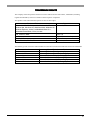
The following terms used in this manual differ from the above mentioned formal trade names and trademarks.
Term used in this manual
Windows 98
Windows 98 SE
Winoows Me
Windows NT
Windows 2000
Windows XP
Formal Trade Name or Trademark
Microsoft Windows 98 Operating System
Microsoft Windows 98 SE Operating System
Microsoft Windows Me Operating System
Microsoft Windows NT Operating System
Microsoft Windows 2000 Operating System
Microsoft Windows XP Operating System
0-2
HO
W TO USE THIS MANU
AL
HOW
MANUAL
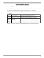
Structure of This Manual
This manual, titled “Pro-Server with Pro-Studio for Windows Operation Manual” describes how to use the
“Pro-Server with Pro-Studio for Windows” software, hereinafter referred to as “this software”
The following table describes the GP-PRO/PBIII for Windows software’s manuals, which are often referred
to in this manual.
Vol. 1
Operation Manual
Vol. 2
Tag Reference Manual
Vol. 3
Parts List
Vol. 4
Device/PLC Connection
Manual
Describes the procedures for the installation and
operation of GP-PRO/PBIII for Windows.
Includes detailed descriptions on the “tags” used to
specify the functions used on the GP’s screen.
Describes the library of pre-made Parts included with
this product as well as a variety of diagram symbols.
Describes the procedures to create connections between GP series units and other manufacture PLCs.
In addition to this manual, information on additional/modified functions may be provided as data files.
0-3
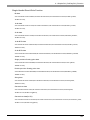
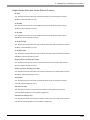
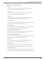
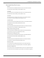
TABLE OF CONTENTS
PREF
ACE ................................................................................................................. 1
PREFA
NO
TE ........................................................................................................................ 1
NOTE
TRADEMARK RIGHTS ............................................................................................ 2
HO
W TO USE THIS MANU
AL .................................................................................. 3
MANUAL
HOW
TABLE OF CONTENTS ........................................................................................... 4
MANU
AL SYMBOLS AND TERMINOLOGY ........................................................... 9
MANUAL
PRECA
UTIONS ...................................................................................................... 10
PRECAUTIONS
PACKA
GE CONTENTS .......................................................................................... 11
CKAGE
OPERA
TING ENVIR
ONMENT ............................................................................... 12
OPERATING
ENVIRONMENT
Chapter 1 Intr
oduction
Introduction
1.1
1.2
1.3
Outline ......................................................................................................... 1-2
What is the 2-W
ay Driver? ......................................................................... 1-3
2-Wa
System Configuration ................................................................................ 1-4
1.3.1 External Configuration .................................................................................................... 1-4
1.3.2 Internal Configuration ..................................................................................................... 1-5
1.4
Application Interfaces .............................................................................. 1-11
1.4.1 DDE function Outline .....................................................................................................
1.4.2 Simple DLL Function .....................................................................................................
1.4.3 OPC Interface Function .................................................................................................
Backup
Storag
1.4.4 SRAM Bac
kup Data Stora
ge Function .........................................................................
1.5
1-11
1-12
1-13
1-14
Pr
ovider Inf
ormation Outline ................................................................... 1-15
Pro
Information
1.5.1 Pr
oviding Inf
ormation to the Host ................................................................................ 1-15
Pro
Information
oviding Inf
ormation between GPs ............................................................................ 1-16
Pro
Information
1.5.2 Pr
vie
w .............................................................................................. 1-17
Overvie
view
1.5.3 Action Feature Over
1.6
1.7
Over
vie
w of Data Vie
w ............................................................................. 1-18
Overvie
view
View
Configuring the System ........................................................................... 1-19
Chapter 2 Pr
o-Ser
ver Fundamentals
Pro-Ser
o-Server
2.1
2.2
Installing the Software ............................................................................... 2-2
Star
ting and Exiting the Software ............................................................. 2-6
Starting
2.2.1 Using Pr
o-Studio ............................................................................................................. 2-6
Pro-Studio
o-Studio ......................................................................................................... 2-10
Pro-Studio
2.2.2 Exiting Pr
Starting
Pro-Ser
o-Server
2.2.3 Star
ting and Exiting Pr
o-Ser
ver ................................................................................... 2-11
2.3
Screen Item Names and Functions ......................................................... 2-13
0-4
Chapter 3 Operation
3.1
Registering Netw
ork Entr
y Nodes ............................................................ 3-2
Network
Entry
3.1.1 Registering a Netw
ork Node ........................................................................................... 3-2
Network
ching a Netw
ork Node ............................................................................................. 3-5
Searc
Network
3.1.2 Sear
3.2
Registering Symbols .................................................................................. 3-7
3.2.1 Impor
ting Symbols ........................................................................................................
Importing
Exportt ...............................................................................................................
3.2.2 Symbol Expor
Importing
C-Pac
acka
kag
3.2.3 Impor
ting C-P
ac
ka
ge Symbol .......................................................................................
Checking
C-Pac
acka
kag
3.2.4 Chec
king C-P
ac
ka
ge Symbol .......................................................................................
3.3
3-10
3-11
3-12
3-16
Registering Pr
ovider Data ....................................................................... 3-19
Pro
3.3.1 Chec
king ffor
or Pr
ovider Data Err
or
s ............................................................................... 3-29
Checking
Pro
Error
ors
3.3.2 Action Items ................................................................................................................... 3-31
3.4
3.5
3.6
3.7
Using the DDE Function .......................................................................... 3-32
A Suppor
Using the VB
VBA
Supportt Function ............................................................ 3-37
Sa
ving Bac
kup Data in SRAM ................................................................. 3-44
Saving
Backup
De
vice Data Bac
kup and Restoration ..................................................... 3-46
Device
Backup
3.7.1 De
vice Data Bac
kup ...................................................................................................... 3-46
Device
Backup
vice Data .................................................................................................. 3-50
Device
3.7.2 Restoring De
3.8
3.9
GP Capture Data Sa
ving Function .......................................................... 3-53
Saving
Security Function ..................................................................................... 3-55
3.9.1 User Le
vel P
ass
wor
d Settings ...................................................................................... 3-55
Level
Pass
assw
ord
ass
wor
d Setup ............................................................................................... 3-57
Pass
assw
ord
3.9.2 Remote P
3.10 Configuring the System ........................................................................... 3-59
3.11 Configuring the Netw
ork .......................................................................... 3-61
Network
3.11.1 Configuring Ethernet Car
ds .......................................................................................... 3-64
Cards
3.12 Printing the Setting Data ......................................................................... 3-65
3.13 Other Instructions .................................................................................... 3-66
3.13.1 Special Pr
otocol ............................................................................................................. 3-66
Protocol
dress ffor
or Windo
ws Computer .................................................................................. 3-68
Address
Windows
3.13.2 Ad
0-5
Chapter 4 Action Items
4.1
Over
vie
w ..................................................................................................... 4-2
Overvie
view
4.1.1 Action Item Registration ................................................................................................. 4-3
ailable
4.1.2 Availab
le Action Items .................................................................................................... 4-4
4.2
Registering Action Items ........................................................................... 4-7
4.2.1 Registering Action Items ................................................................................................ 4-7
arameter
s .............................................................................................. 4-9
Parameter
arameters
4.2.2 Setting Action P
Pro
Information
4.2.3 Registering Pr
ovider Inf
ormation ................................................................................. 4-15
4.3
Registering Action Item P
arameter
s ....................................................... 4-18
Parameter
arameters
4.3.1 “Star
“Startt Application” Action Item ....................................................................................
Alertt Feature) .........................................................................
4.3.2 Alarm Log (with Sound Aler
4.3.3 Upload of GP Log Data ..................................................................................................
Download
wnload of GP Filing Data .......................................................................
4.3.4 Automatic Do
4.3.5
4.3.6
4.3.7
4.3.8
Automatic Upload of GP Filing Data ............................................................................
Automatic Upload of Access Data ...............................................................................
Download
Automatic Do
wnload of Access Data ..........................................................................
Download
Do
wnload Recipe data ffor
or Excel ..................................................................................
4.3.9 Writes Data to E-Mail .....................................................................................................
4.3.10 Upload to the database .................................................................................................
Download
from
4.3.11 Do
wnload fr
om the database ........................................................................................
4.3.12 Upload of JPEG Data .....................................................................................................
4-18
4-20
4-23
4-27
4-29
4-32
4-36
4-39
4-42
4-45
4-51
4-56
4.3.13 Writes Data to CSV file .................................................................................................. 4-59
om CSV file ............................................................................................. 4-60
from
4.3.14 Writes Data fr
4.4
Using ‘Create repor
reportt using Excel’ Action ............................................... 4-65
4.4.1 Registration Pr
ocedure of ‘Create repor
Procedure
reportt using Excel’ Action .................................
ormation Writab
le to the Repor
Information
Writable
Reportt ...............................................................................
4.4.2 Inf
Reportt Pr
Prototype
4.4.3 Creating the Repor
ototype .....................................................................................
Reportt Action .............................................................................................
4.4.4 Setting the Repor
4-67
4-68
4.4.5 Registering Commands ................................................................................................
anel (Man
ual Star
t) ....................................................................
Panel
(Manual
Start)
4.4.6 Creating Command P
Pro
Information
(Auto
Start)
4.4.7 Registering Pr
ovider Inf
ormation (A
uto Star
t) ............................................................
reportt using Excel’ Action ....................................
4.4.8 When Registering/Using ‘Create repor
4-79
4-84
4-69
4-70
4-87
4-92
Chapter 5 GP Setup
5.1
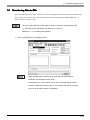
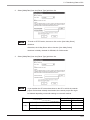
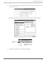
Transf
erring Data to GPs ........................................................................... 5-2
ransferring
Chapter 6 Tools
6.1
6.2
6.3
6.4
De
vice Monitoring ...................................................................................... 6-2
Device
GP Status Monitoring ................................................................................. 6-5
Read P
erf
ormance Measuring Tool ........................................................... 6-7
Perf
erformance
Log Vie
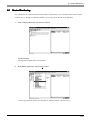
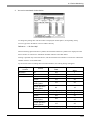
wer ................................................................................................. 6-10
Viewer
6.4.1 2W
ay Log Vie
wer ............................................................................................................ 6-10
2Wa
Viewer
wn Men
u of Eac
h Log Vie
wer Men
u ................................................................. 6-12
Pull-Down
Menu
Each
Viewer
Menu
6.4.2 Pull-Do
hing Between Online and Offline Modes ............................................................ 6-14
Switching
6.4.3 Switc
0-6
Chapter 7 Data Vie
w
View
7.1
7.2
Data Vie
w Over
vie
w .................................................................................... 7-2
View
Overvie
view
De
vice Vie
w ................................................................................................. 7-4
Device
View
7.2.1 Setting Sampling Tar
get De
vice ..................................................................................... 7-4
arg
Device
7.2.2 Setting the Data Sampling Condition ............................................................................ 7-9
7.2.3 Editing Sampled Data .................................................................................................... 7-18
7.2.4 Option ............................................................................................................................. 7-21
k Feature ........................................................................................................... 7-26
7.2.5 Pla
ybac
Playbac
yback
7.2.6 Other Features ............................................................................................................... 7-28
7.3
GP-Vie
wer .................................................................................................. 7-32
GP-Viewer
7.3.1 Star
ting GP-Vie
wer ........................................................................................................
Starting
GP-Viewer
7.3.2 Setting the Data Sampling Condition ..........................................................................
7.3.3 Editing Sampled Data ....................................................................................................
Drawing
7.3.4 Setting Dra
wing .............................................................................................................
Playbac
yback
ybac
k Feature ...........................................................................................................
7.3.5 Pla
7-32
7-34
7-43
7-46
7-48
7.3.6 Other Features ............................................................................................................... 7-50
7.4
7.5
Chec
king the Data Sampling Status ....................................................... 7-62
Checking
System Time Bar ....................................................................................... 7-64
Chapter 8 Maintenance via Ethernet
8.1
8.2
Transf
erring Netw
ork Pr
oject Files ........................................................... 8-2
ransferring
Network
Project
erring Onl
y Updated Screen Data to GPs ...................................... 8-3
Transf
ransferring
Only
Chapter 9 Simple DLL Function
9.1
Simple DLL (Pr
oEasy
.DLL) Function ........................................................ 9-2
(ProEasy
oEasy.DLL)
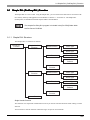
9.1.1 Simple DLL Structure ...................................................................................................... 9-2
vice Read/Write Function ........................................................................................... 9-5
Device
9.1.2 De
Control
9.1.3 System and Other Contr
ol Functions .......................................................................... 9-16
9.1.4 Precautions When Using Function .............................................................................. 9-34
9.2
Examples of Simple DLL Function ......................................................... 9-45
9.2.1 VB Feature Help ............................................................................................................
9.2.2 VC Function Help ...........................................................................................................
9.2.3 Using simple DLL functions with Visual Basic .NET ....................................................
9-45
9-58
9-79
Chapter 10 OPC Ser
ver
Server
10.1 OPC Ser
ver ............................................................................................... 10-2
Server
10.2 Connecting fr
om an OPC Client .............................................................. 10-6
from
0-7
Appendices
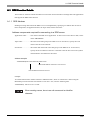
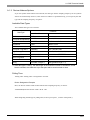
A.1 DDE Function Details ................................................................................. A-2
A.1.1 DDE Ad
dress .................................................................................................................... A-2
Address
vice Ad
dress Options ................................................................................................. A-3
Device
Address
A.1.2 De
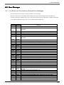
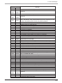
A.2 Err
or Messa
ges ........................................................................................... A-4
Error
Messag
A.2.1 Pr
o-Ser
ver with Pr
o-Studio ffor
or Windo
ws Err
or Messa
ges ........................................... A-4
Pro-Ser
o-Server
Pro-Studio
Windows
Error
Messag
or Messa
ges and Syslog Features ................................................... A-11
2-Wa
Error
Messag
A.2.2 2-W
ay Driver Err
A.3
A.4
A.5
A.6
Scale Con
ver
sion using Excel ................................................................. A-15
Conver
version
GP Ethernet Settings ............................................................................... A-16
Optimizing Comm
unication Speed ......................................................... A-18
Communication
ws XP Security Le
vel ................................................... A-20
Changing Windo
Windows
Level
0-8
MANU
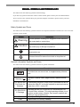
AL SYMBOLS AND TERMINOLOGY
MANUAL
This manual uses the following symbols and terminology.
If you have any questions about the contents of this manual, please contact your local GP distributor.
Also, If you have any question about your personal computer or Windows, please contact your local
distributor or manufacturer.
Safety Symbols and Terms
This manual uses the following symbols and terms for important information related to the correct and safe
operation of this product.
Symbol
Warning
Caution
Description
Incorrect operation resulting from negligence of this instruction
may cause death or serious injury.
Incorrect operation resulting from negligence of this instruction
may cause injury or damage to equipment.
Indicates Instructions/Procedures that must be performed to ensure
correct product use.
Indicates Actions/Procedures that should not be performed.
General Information Symbols and Terms
This manual uses the following symbols and term for general information.
Symbol
Description
Provides hints on correct use, or supplementary information.
Reference
Pro-Server with
Pro-Studio for
Windows
GP-PRO/PB III
C-Package
Indicates (manual name, page number) related information.
Downloading Ethernet (2-Way Driver) information to the GP
allows the Host PC to use the network to send and receive
data from a PLC, via the GP.
Includes the new GP-PRO/PB III for Windows and ProControl Editor software. This single package allows you to
perform a aide variety of tasks, from screen creation and
editing to logic programming.
PLC
Acronym for Programmable Logic Controller.
FGW
Abbreviation for Factory Gateway
0-9
PRECA
UTIONS
PRECAUTIONS
Product Usage Precautions
To prevent program malfunctions or accidents, be sure to observe the following instructions:
Warning
Touch panel switches should NOT be used for a device’s Emergency Stop switch. Generally speaking, all
industrial machinery/systems must be equipped with a mechanical emergency stop switch that can only
be operated by people. Also, for other kinds of systems, similar mechanical switches must be provided to
ensure safe operation of that system.
Cautions
• Do not turn off your personal computer’s power switch during the execution of a program. Also, be
sure your PC “Power Management” area’s “System Standby” and “Turn off hard disk” are set to
“Never” .
• Do not change the contents of this product’s project files using the Text Editor software.
CD-ROM Usage Precautions
To prevent CD-ROM damage or malfunctions, please observe the following instructions:
• Do not remove a CD-ROM disk from the CD-ROM drive while the operation lamp is lit.
• Do not touch the CD-ROM recording surface.
• Do not store the CD-ROM disk in a place where it may be exposed to extremely high or low temperatures, high humidity, or dust.
0-10
PACKA
GE CONTENTS
CKAGE
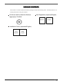
The Pro-Server with Pro-Studio for Windows package includes the following items. Check that there are no
missing items before using the software.
Pro-Server with Pro-Studio for Windows
Application CD-ROM
User Registration (Japanese/English)
Japanese
English
Installation Guide (Japanese/English)
(Front)
Japanese
(Back)
English
0-11
OPERA
TING ENVIR
ONMENT
OPERATING
ENVIRONMENT
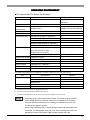
Pro-Server with Pro-Studio for Windows
Remark
Specification
Item
Pentium 133MHz or faster
Personal Computer
PC/AT compatible
Display
VGA (640 x 480) or higher
64 bit color or higher
20 MB or more
30 MB or more is recommended
processor
Hard Disk Space
Requirements
Memory Requirements 32 MB or more
CD-ROM Drive
128 MB or more is recommended
Windows compatible
OS Requirements*1 Windows 98 (English or Japanese)
*2
Windows Me (English or Japanese)
*2
Windows NT 4.0 (English or Japanese)
Service Pack 3.0 or higher
Windows 2000 (English or Japanese)
Related software
Windows XP (English or Japanese)
*2
Microsoft Access 97 or later
When using action contents
Microsoft Excel 97 or later
Browser (IE V4.0 or later)
Visual Studio 6.0 SP3 or higher
When using Simple DLL Function
Supported languages Japanese, English
Printer
Any printers that your OS supports
Mouse
Windows compatible
Ethernet Board
10BASE-2/5/T, 100BASE-T
Network Configuration TCP/IP Protocol
Additional Items
Ethernet Hub, Ethernet cables, etc.
Mouse is required for operation.
Set up from Control Panel.*3
User supplied
The following operating environment is required when you use the OPC Server.
Item
Specification
OS Requirements
Windows NT 4.0
Remark
Service Pack 3.0 or higher
Windows 2000
Windows XP
Hard Disk Space
100 MB or more
Memory
64 MB or more
*1
*2
Pro-Server Ver. 4.5 does not support Windows95.
You can not use this feature with the OPC Server.
*3
Until the TCP/IP protocol is set, Pro-Server with Pro-Studio cannot be used.
• Depending on the type of Ethernet hub used, Pro-Server may be unable to
transmit data. Be sure to test and confirm the compatibility of Pro-Server
with your Ethernet network prior to installing a complete Pro-Server with
Pro-Studio for Windows system.
• When using a Switching Hub, if the GP and the Switch Hub are started at the
same time, a communication error can occur. If the Switching Hub cannot be
started first, Set the GP’s [START TIME] to slow the start of the GP.
0-12
When installing and using the GP-Viewer, the following system environment is required.
Related Software
Microsoft Internet Explorer Ver. 5.0 or
Includes JavaVM
higher
(Ver.5.0.3176 or higher)
• When using Microsoft Internet Explorer Ver. 5.0, some of the features may not
display as desired. To solve this problem, please use Microsoft Internet
Explorer Ver. 5.01 or later, in combination with the latest version of Microsoft
Java VM. The latest versions of Microsoft Internet Explorer and Microsoft Java
VM can be downloaded from Microsoft’s homepage.
• When using GP-Viewer on a PC with GP-Web installed, please be sure the
version of GP-Web is 1.5 or later.
0-13
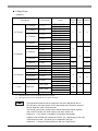
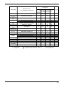
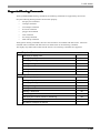
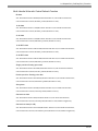
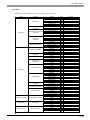
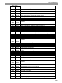
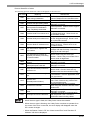
2-Way Driver
Hardware
Series Name
Product Name
GP-377Rseries
GP-377RT
GP-477Rseries
GP-477RE
GP77Rseries
GP-577RS
GP-577Rseries
GP-577RT
GP-2300series
GP-2400series
GP-2300L
GP-2300T
GP-2400T
GP-2500T
GP-2500series
GP2000series
GP-2501series
GP-2600series
GP-2600T
GP-2601series
GLC2400series
GP-2601T
GLC2300L
GLC2300T
GLC2400T
GLC2500series
GLC2500T
GLC2600series
GLC2600T
GLC2300series
GLC2000series
GP-2500L
GP-2500S
GP-2501S
GP-2501T
IT2400 TypeA
ITseries
IT2400series
IT2400 TypeB
Factory Gateway
Factory Gateway
Model
GP377R-TC11-24V
GP377R-TC41-24V
GP477R-EG11
GP477R-EG41-24VP
GP577R-SC11
GP577R-SC41-24VP
GP577R-TC11
GP577R-TC41-24VP
GP2300-LG41-24V
GP2300-TC41-24V
GP2400-TC41-24V
GP2500-TC11
GP2500-TC41-24V
GP2500-LG41-24V
GP2500-SC41-24V
GP2501-SC11
GP2501-TC11
GP2600-TC11
GP2600-TC41-24V
GP2601-TC11
GLC2300-LG41-24V
GLC2300-TC41-24V
GLC2400-TC41-24V
GLC2500-TC41-24V
GLC2500-TC41-200V
GLC2600-TC41-24V
GLC2600-TC41-200V
IT2400-TC41-GP
IT2400-TC41-GP200V
IT2400-TC41-GLC
IT2400-TC41-GLC200V
FGW-SE41-24V
*1
GP Ethernet I/F Unit or the Multi Unit E is required.
*2
GP Ethernet I/F Unit or the Multi Unit E can be attached.
Built-in External
Ethernet Ethernet Comment
Unit
Unit
×
*1
×
-
*2
×
*1
*2
×
*1
×
-
*2
×
-
-
-
The Expansion Ethernet unit is required to use the 2-Way Driver with a
GP77R series, GP-2501 series or GP-2601 series unit. Therefore, protocol
for the expansion units cannot be used.
You cannot use both the 2-Way Driver and the Ethernet protocol together
with a GP77R series, GP-2501 series or GP-2601 series unit.
Reference → “Pro-Server compatible PLC Vendors and Models”
Settings used will differ (IP Addresses Port No., etc.), depending on the type
of Ethernet unit used, i.e. built-in type or expansion unit type.
Reference → “Using an Ethernet protocol with the 2-Way Driver”
0-14
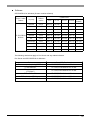
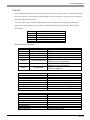
Software
GP-PRO/PB III for Windows (Screen creation software)
Screen Creation
Software
GP-PRO/PBIII for
Windows
System Version
Language
Software
Version
GP70
GP77R
GP377R
GP2000
Factory
Gateway
Japanese
Ver.3.0
Ver.1.51
Ver.2.40
-
-
-
ML
Ver.3.0
Ver.1.51
Ver.2.40a
-
-
-
Japanese
Ver.4.0
Ver.1.54
Ver.2.60
Ver.2.60
-
-
Japanese/ML
Ver.5.0
Ver.1.55
Ver.2.64
Ver.2.64
Ver.3.10
-
Japanese
Ver.6.0
Ver.1.55
Ver.2.68
Ver.2.68
Ver.3.30
-
ML
Ver.6.0
Ver.1.55
Ver.2.68
Ver.2.68
Ver.3.30
Ver.3.42
Japanese/ML
Ver.6.1
Ver.1.55
Ver.2.69
Ver.2.69
Ver.3.50
Ver.3.42
Japanese/ML
Ver.6.2 SP1
Ver.1.55
Ver.2.69d Ver.2.69d
Ver.3.53
Ver.3.42
Japanese/ML
Ver.6.3 SP2
Ver.1.55d
Ver.2.69j
Ver.2.69j
Ver.3.53b
Ver.3.56
Japanese/ML
Ver.7.0
Ver.1.55e Ver.2.69k Ver.2.69k
Ver.4.00
Ver.3.56
The following restrictions apply to Pro-Server and any related software.
Pro-Server and GP-PRO/PB III for Windows
Feature
Compatibility Requirement
GP screen capture (capturing JPEG files)
GP-PRO/PB lll for Windows V6.0 or later
LS area extension
Online screen upload
( GP-Viewer )
CF Card Online Write
GP-PRO/PB lll for Windows V6.0 or later
GP-PRO/PB lll for Windows V6.1 or later
CF Card access all File Names
GP-PRO/PB lll for Windows V7.0 or later
Increased number of Alarm Blocks
GP-PRO/PB lll for Windows V7.0 or later
GP-PRO/PB lll for Windows V6.0 or later
0-15
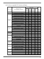
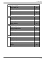
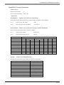
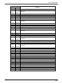
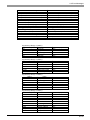
Pro-Server compatible PLC Vendors and Models
2-Way Driver
Vendor Name
DIGITAL
Electronics
Mitsubishi
Electric
Omron
Sharp Corp.
Yokogawa
Electric Corp.
Fuji Electric
Co.,Ltd.
Toyota
Machine
Warks, Ltd.
Yaskawa
Electric Corp.
Hitachi Ltd.
Hitachi
Industrial
Equipment
Systems.
Device/PLC Type
(in GP-PRO/PBIII for Windows)
MEMORY LINK SIO Type
MEMORY LINK Ethernet Type
MITSUBISHI MELSEC-AnN(LINK)
MITSUBISHI MELSEC-AnN(CPU)
MITSUBISHI MELSEC-AnA(LINK)
MITSUBISHI MELSEC-AnA(CPU)
MITSUBISHI MELSEC-A(JPCN1)
MITSUBISHI MELSEC-A(ETHER)
MITSUBISHI MELSEC-FX(CPU)
MITSUBISHI MELSEC-FX(CPU2)
MITSUBISHI MELSEC-FX2(LINK)
MITSUBISHI MELSEC-FX 1:N Comm.
MITSUBISHI MELSEC-QnA(LINK)
MITSUBISHI MELSEC-QnA(CPU)
MITSUBISHI MELSEC-Q(ETHER)
MITSUBISHI MELSECNET/10
MITSUBISHI FREQROL SERIES
CC-Link Type
OMRON SYSMAC-C SERIES
OMRON SYSMAC-C 1:n Comm.
OMRON SYSMAC-CV SERIES
OMRON SYSMAC-CS1 SERIES
OMRON SYSMAC-CS1(ETHER)
OMRON THERMAC NEO SERIES
SHARP NewSatellite JW Series
YOKOGAWA FACTORY ACE 1:1 Comm.
YOKOGAWA FACTORY ACE 1:n Comm.
YOKOGAWA FA-M3 (ETHER)
FUJI MICREX-F SERIES
FUJI MICREX-F SERIES (FLT)
FUJI MICREX-F SERIES (T LINK)
FUJI FLEX-PC (LINK)
FUJI FLEX-PC (CPU)
FUJI INVERTER
FUJI TEMPERATURE PXR
TOYOTA TOYOPUC-PC2 SERIES
TOYOTA TOYOPUC-PC2 1:n Comm.
TOYOTA TOYOPUC-PC3J SERIES
TOYOTA TOYOPUC-PC3J 1:n Comm.
YASUKAWA Memocon-SC SERIES
YASUKAWA GL120/130 SERIES
YASUKAWA MP2000/920 (ETHER)
YASUKAWA PROGIC8 SERIES
YASUKAWA MP900/CP9200SH SERIES
YASUKAWA INVERTER
HITACHI HIDIC-S10a SERIES
HITACHI HIDIC-S10a (JPCN1)
HITACHI HIZAC-EC SERIES
HITACHI IES SJ300/L300P Series
HITACHI HIDIC H SERIES
HITACHI HIDIC H2 SERIES
HITACHI HIDIC-H (ETHER)
GP-2500 GP-2300
GP77R
GP-2600 GP-2400
GP-2501
GLC2500 GLC2300
GP-2601
GLC2600 GLC2400
O
O
O
X
O
O
O
O
O
O
O
O
O
O
O
O
O
O
X
O
X
X
O
O
O
O
O
O
O
O
O
O
O
O
O
O
O
O
O
O
O
O
X
O
O
X
X
O
O
O
X
O
X
O
O
O
O
O
O
O
O
O
O
O
O
X
O
O
O
O
O
O
O
O
O
O
O
O
X
O
O
O
O
O
O
O
O
X
O
X
O
O
O
O
O
O
O
O
O
O
O
O
O
O
O
O
O
O
O
O
O
O
O
O
O
O
O
O
O
O
O
O
O
O
O
O
O
O
O
O
O
O
O
O
O
X
O
X
O
O
O
O
O
O
O
O
O
O
O
O
X
Comment
FGW
O
O
O
O
O
O
X
O
O
O
O
O
O
O
O
X
O
X
O
O
O
O
*2
*1
*2
*2
*3
*1
*2 *3
O
O
O
O
O
O
O
X
O
O
O
O
O
O
O
O
O
O
O
O
O
O
O
X
O
O
O
O
*2
*1
*1
*2 *3
0-16
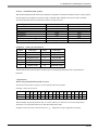
2-Way Driver
Vendor Name
Toshiba Corp.
Matsushita
Electric
Works, Ltd.
Koyo
Electronics
Industries Co.
Toshiba
Machine Co.,
GE Fanuc
AutoMation
Fanuc Motion
Controller
IDEC Izumi
Corp.
Siemens AG
Rockwell
(Allen-Bradley)
Keyence Corp.
Shinko
Electric
Matsushita
Electric
Modicon Corp.
FATEK
Device/PLC Type
(in GP-PRO/PBIII for Windows)
TOSHIBA PROSEC-EX2000 SERIES
TOSHIBA PROSEC-T SERIES
TOSHIBA PROSEC-T (ETHER)
GP-2500 GP-2300
GP77R
GP-2600 GP-2400
GP-2501
GLC2500 GLC2300
GP-2601
GLC2600 GLC2400
O
O
O
O
O
O
X
O
O
Comment
FGW
O
O
O
MATSUSHITA MEWNET-FP SERIES
O
O
O
O
KOYO KOSTAC-SG8 SERIES
KOYO KOSTAC SR21/22 SERIES
KOYO DL-305 SERIES
KOYO DL-205/405 SERIES
TOSHIBA TC200 SERIES
TOSHIBA MACHINE TC200-S SERIES
O
O
O
O
O
O
O
O
O
O
O
O
O
O
O
O
O
O
O
O
O
O
O
O
GE FANUC SERIES 90 SNP-X
O
O
O
O
GE FANUC SERIES 90-30/70 SNP
O
O
O
O
FANUC POWER MATE SERIES
O
O
O
O
IZUMI IDEC_1
IZUMI IDEC_2
IZUMI IDEC_3
IZUMI MICRO3
IDEC FC3/FC4A Series
SIEMENS S5 90-115 SERIES
SIEMENS S5 135-155 SERIES
SIEMENS S5 3964(R) Protocol
Siemens S7-200 PPI
Siemens S7-200 via MPI
Siemens S7-300/400 via MPI
SIEMENS S7-300/400 (ETHER)
SIMATIC S7 via 3964/RK512
SIMATIC 545/555 CPU
O
O
O
O
O
O
O
O
O
O
O
O
O
O
O
O
O
O
O
O
O
O
O
O
O
O
O
O
O
O
O
O
O
O
O
O
O
O
O
O
O
O
O
O
O
O
O
O
O
O
O
O
O
O
O
O
Allen Bradley PLC-5 SERIES
O
O
O
O
Allen Bradley SLC500 SERIES
AB Data Highway Plus
AB Slc500 DH485
AB Remote IO
Allen Bradley ControlLogix DFI
AB ControlLogix (EtherNet/IP)
Allen Bradley SLC5/05 (ETHER)
KEYENCE KZ300 SERIES
KEYENCE KZ-A500 (CPU)
KEYENCE KZ-A500 (LINK)
KEYENCE KV-10_80RW/TW SERIES
KEYENCE KV-10_40A/D SERIES
KEYENCE KV-700 SERIES (CPU)
O
X
O
O
X
O
X
X
X
O
O
O
O
O
O
O
O
O
X
O
O
X
O
O
O
O
O
O
O
O
O
O
O
O
O
O
O
X
O
O
O
O
O
O
O
O
O
SHINKO SELMART SERIES
O
O
O
O
MATSUSHITA MINAS-A/S SERIES
Panadac 7000 SERIES
Modicon Modbus (MASTER)
Modicon Modbus (SLAVE)
Modicon Modbus Plus
FATEK FACON FB
O
O
O
O
X
O
O
O
O
O
O
O
O
O
X
O
O
O
O
O
X
O
O
*2
*3
*5
*6
*3
*3
*3
*6
*3
*3
0-17
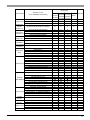
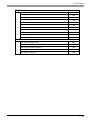
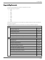
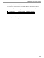
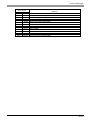
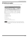
2-Way Driver
Device/PLC Type
(in GP-PRO/PBIII for Windows)
Vendor Name
ORIM VEXTA
Yamatake
Corporation
Toho Electronics
Inc.
RKC Instrument
Inc.
Shinko Technos
Corp.
Fenwal Co.,Ltd
JT Engineering
inc.
MEIDENSHA
CORPORATION.
SHIMADEN
Co.,Ltd.
CHINO Corp.
Schneider
Electric.
PROFIBUS
INTERBUS
JPCN-1
DeviceNet
TOSHIBA
SCHNEIDER
Ubon
ORIM VEXTA E1 SERIES
GP-2500 GP-2300
GP77R
GP-2600 GP-2400
GP-2501
GLC2500 GLC2300
GP-2601
GLC2600 GLC2400
O
O
O
Comment
FGW
O
YAMATAKE SDC SERIES
O
O
O
O
TOHO ELECTRONICS TTM SERIES
O
O
O
O
RKC CB/SR-Mini SERIES (MODBUS)
RKC CB/REX-F/LE100 (RKC)
O
O
O
O
O
O
O
O
SHINKO TECHNOS INDICATING
O
O
O
O
FENWALl AL SERIES
O
O
O
O
JTE Analyzer
O
O
O
O
MEIDENSHA Ethernet
X
O
O
O
SHIMADEN CONTROLLER
O
O
O
O
CHINO CONTROLLER (MODBUS)
Schneider TSX via UNI-TELWAY
Schneider Modbus TCP (ETHER)
Schneider Modbus RTU 1:n comm.
PROFIBUS-DP
INTERBUS SLAVE
JPCN-1 (Standard)
DeviceNet Slave I/O
O
O
O
O
X
X
X
X
O
O
O
O
O
O
O
O
O
O
O
O
X
X
X
X
O
O
O
O
X
X
X
X
TOSHIBA SCHNEIDER INVERTER
O
O
O
O
Ubon UPZ Series
O
O
O
O
O...Supported
...Supported with restriction (See *3)
*2
*6
*6
*6
*1
*1
*1
*1
X...Not Supported
0-18
Protocols before V1.2 can be used, however it cannot detect write errors.
Although you can use protocol older than V1.2, it cannot detect a write error.
You can check the protocol version on “Status Monitor”.
Reference → “6.2 GP Status Monitoring”
*1
An expansion Ethernet unit is required to use the 2-Way Driver with GP77R/GP-2501/GP-2601 series
units. The attachment of this unit prevents the attachment of any other expansion units, which in turn
prevents the use of any other protocols.
Since Expansion Units cannot be used with GP-2300/GP-2400 Series, GLC2300/GLC2400 Series and
Factory Gateway units, Expansion Unit protocols also cannot be used.
*2
You cannot use both the 2-Way Driver and Ethernet protocols at the same time on GP77R/GP-2501/GP-2601
series units.
*3
You can use the 2-Way Driver together with listed protocols, however, there are device restrictions for ProServer access. Screens only need to be created for the devices that can be accessed.
Protocol Name
MITSUBISHI MELSECNET/10
Restriction
Can access only the link device, LS Area
and symbols designated in a GP-PRO/PB III
project file (.prw).
AB Slc500 DH485
Siemens S7-200 via MPI
OMRON SYSMAC-CS1 (ETHER)
HITACHI HIDIC H (ETHER)
Can access only the LS Area and symbols
designated in a GP-PRO/PB III project file
(.prw).
Allen Bradley SLC5/05 (ETHER)
Allen Bradley PLC-5 Data Highway Plus
AB Remote I/O
Can access only the LS Area.
Modicon Modbus Plus
*4
This protocol cannot be used with the 2-Way Driver.
*5
When accessing a device connected one-to-one with a PLC, it is not necessary to register Symbols with
GP-PRO/PBIII for Windows.
However, when connecting to multiple PLC units or accessing an Expansion device, Symbols must be
registered with GP-PRO/PBIII for Windows.
*6
Simultaneous use of the 2-Way Driver is possible, however, only the LS area and symbols set via the CPackage03 project file can be accessed. The Factory Gateway cannot be used to enter protocol settings.
0-19
1
Introduction
This chapter describes how to use this software to configure a system in which you
can gather data from devices/PLCs connected to networked GPs.
1.1
1.2
Outline
What is the 2-Way Driver?
1.3
1.4
System Configuration
Application Interfaces
1.5
1.6
Provider Information Outline
Overview of Data View
1.7
Configuring the System
1.1 Outline
1.1 Outline
The Pro-Server software reads/writes/collects data to and from PLC, and GP’s data via a network (Ethernet).
Pro-Server on your PC lets you use commercially available application software or programs you have
created to read/write/collect data on the GPs and PLCs connected to the network.
It can also save and playback (Playback Feature) the saved data.
1-2
1.2 What is the 2-Way Driver?
1.2 What is the 2-W
ay Driver?
2-Wa
The 2-Way Driver is software that allows the host PC to access data on GPs or PLCs connected to a network
(Ethernet). One advantage of this software is that you can transfer data to the host PC, regardless of type of
PLC being used.
To use the 2-Way function, Pro-Server software and an Ethernet compatible GP unit are required.
The GP reads and writes data via the 2-Way driver only when it is not
serving as a display and operation panel, which is its first priority. Also,
reading or writing a large volume of data may cause the GP to temporarily
stop refreshing its display.
1-3
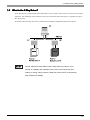
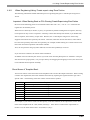
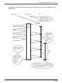
1.3 System Configuration
1.3 System Configuration
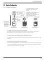
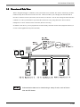
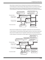
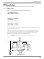
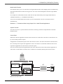
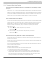
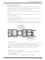
1.3.1 External Configuration
• Pro-Studio allows you to easily
designate a PLC device as a
symbol.
• Pro-Studio
• Pro-Server
Ethernet
• Designate a symbol using Excel,
SCADA software, and VB
applications, and Pro-Server can
easily read that data out.
GP
GP
GP
2-Way
Driver
2-Way function
The 2-Way Driver
translates PLC
protocols, allowing
data exchange
between many
types of PLCs.
PLC for
Manufacturer A
PLC for
Manufacturer B
PLC for
Manufacturer C
Pro-Studio (Performs Network project file editing/setting)
This software is used to set and register symbols for the GPs and PLCs designated as data providers.
Physical IP addresses, PLC device addresses, etc. can all be converted into symbols.
Pro-Server (Performs Data exchange between applications and GPs)
This software that communicates with GPs according to the requests made by Excel, VB, SCADA or other
applications.
2-Way Driver (Protocol conversion driver built into GPs)
This driver selects the applicable PLC protocol, based on the Pro-Server read/write command. GP77R series
units requires setup and then transfer to the GP unit via the screen editor software GP2000 and GLC2000
series unit 2-Way Driver software is factory installed.
1-4
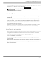
1.3 System Configuration
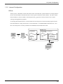
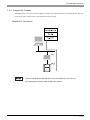
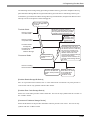
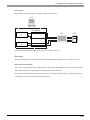
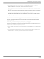
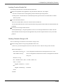
1.3.2 Internal Configuration
Off-line
Inside your PC, information such as node names of the connected GPs, symbol names for accessing the PLC
devices, and information read from the GPs is all set up and controlled via this software. The file in which
this information is stored is called a network project file (*.npj) and is used by Pro-Server for its data
exchange with application programs.
To exchange data with the host PC, each GP must have the 2-Way Driver and the network project information downloaded to it, along with the GP’s screen information, via GP-PRO/PBIII for Windows Ver. 3.0 or
later. The 2-Way Driver is factory installed in the GP2000 and GLC2000 Series units.
Inside of PC
Pro-Studio
GP-PRO/PBIII for Windows
V. 3.0 or later
PL
or
Panel
computer
PC
Network
project file
(.npj)
Project file
(.prw)
• GP system
• Protocols for
various PLCs
• 2-Way Driver
Set up
GP
1-5
1.3 System Configuration
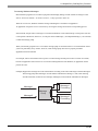
On-line
In response to an application’s request, this software accesses PLC data, by way of the GP, using the network
project file. Prior to using Pro-Server, be sure to first use your PC's GP-PRO/PBIII for Windows software to
download the "2-Way Driver" and your PLC's protocol to the GP unit.
• Transferring screen data in on-line mode or downloading a network project file,
will temporarily cause the Transfer screen to appear and all other data transfer
operations to stop.
• After screen transfer is completed, the screen will re-activate and regular
operation will resume.
1-6
1.3 System Configuration
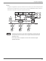
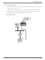
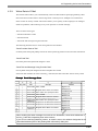
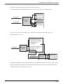
Using an Ethernet protocol with the 2-Way Driver
Pro-face’s GP2000 (GP-2501 does not support this function) and GLC2000 Series units can simultaneously
use an Ethernet communication protocol and the 2-Way Driver feature to communicate with a PLC. However, the IP address and the Port No. used for differ depending on whether the internal Ethernet I/F or the
Expansion Ethernet I/F is used.
Network with only one GP Ethernet I/F
Using the GP/GLC’s internal Ethernet I/F to communicate with a PLC allows you to also use the 2-Way
Driver feature. However, while you will need only one IP Address, you will need to designate two Port No.s.
One will be for when you transfer data to a PLC, and the other will be when using the 2-Way feature.
In order to transfer data to a PLC, you will need to enter your GP/GLC unit’s Ethernet settings via the
OFFLINE mode’s [INITIALIZE] -> [PLC SETUP] -> [PLC SETUP] -> [SETUP ETHERNET INFORMATION] screen. However, the Subnet Mask and IP Address must be entered in the [PLC SETUP] -> [SETUP
ETHERNET EXT. INFORMATION] screen. This data must also be entered in the GP-PRO/PBIII for
Windows software’s Project Manager screen [GP Setup] menu’s [Communication Settings] tab.
The entering of Ethernet settings for communication using the 2-Way Driver feature is done via the previously mentioned OFFLINE mode. Select the [INITIALIZE] -> [PLC SETUP] -> [EXPANSION SETTINGS] -> [ETHERNET SETUP] area, and enter the required setting data there. You need to also enter the
required settings in the Pro-Studio program’s [Register/Edit Node] area, and the [Port No.] in the [Configure] -> [Network] area.
1-7
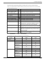
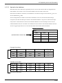
1.3 System Configuration
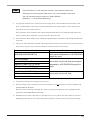
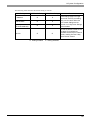
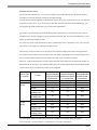
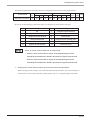
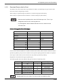
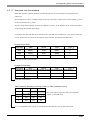
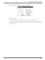
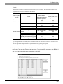
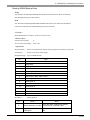
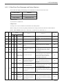
The following table describes what each setting is used for.
Setting
PLC Transfer Settings
2-Way Driver Settings
IP Address
O
X
Subnet Mask
O
X
Gateway
(IP Route Address)
O
X
Port No.
O
O: Setting enabled
O
Remarks
These settings apply to a single
Ethernet I/F and only one setting
value can be entered. When the
PLC Transfer Settings are not
entered, the 2-Way Driver Settings
will be enabled.
Be sure the Port No.s used are not
the same. Port numbers are
allocated continuously for a total of
10 No.s, starting from the 2-Way
Driver Port No. entered.
X: Setting disabled
1-8
1.3 System Configuration
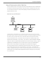
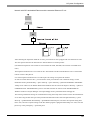
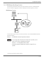
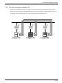
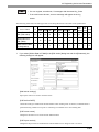
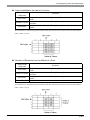
Network with GP’s embedded Ethernet and the extended Ethernet I/F unit
After attaching the Expansion Ethernet I/F Unit, your GP unit is now equipped with two Ethernet I/F units.
This can separate the network between PLC-GP and GP-PC to break up traffic.
(The Ethernet Expansion Unit cannot be used with the GP-2300, GP-2400, GLC2300 or GLC2400 series
units.)
The Expansion Ethernet I/F Unit is used for PLC data transfer and the internal Ethernet I/F is used for data
transfer via the 2-Way Driver.
Use of the Expansion Ethernet I/F Unit will require the setting of a separate IP Address.
In order to transfer data to a PLC, you will need to enter your GP/GLC unit’s Ethernet settings via the
OFFLINE mode’s [INITIALIZE] -> [PLC SETUP] -> [PLC SETUP] -> [SETUP ETHERNET INFORMATION] screen. However, the Subnet Mask and IP Address must be entered in the [PLC SETUP] -> [SETUP
ETHERNET EXT. INFORMATION] screen. This data must also be entered in the GP-PRO/PBIII for
Windows software’s Project Manager screen [GP Setup] menu’s [Communication Settings] tab.
The entering of Ethernet settings for communication using the 2-Way Driver feature via the internal Ethernet
I/F is done using the GP unit’s previously mentioned OFFLINE mode. Select the [INITIALIZE] -> [PLC
SETUP] -> [EXPANSION SETTINGS] -> [ETHERNET SETUP] area, and enter the required setting data
there. Also, enter the required settings in the Pro-Studio program’s [Register/Edit Node] area. Also, enter the
[Port No.] in the [Configure] -> [Network] area.
1-9
1.3 System Configuration
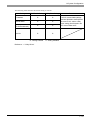
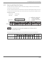
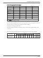
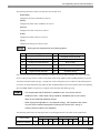
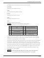
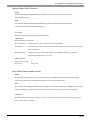
The following table describes what each setting is used for.
Setting
PLC Transfer Settings
2-Way Driver Settings
Remarks
IP Address
O
O
Subnet Mask
O
O
Gateway
(IP Route Address)
O
O
The PLC communication settings
used are allocated to the Expansion
Ethernet I/F Unit, and the 2-Way
Driver settings are allocated to the
GP’s internal Ethernet I/F.
Port No.
O
O
O: Setting enabled
X: Setting disabled
Reference → “2-Way Driver”
1-10
1.4 Application Interfaces
1.4 Application Interfaces
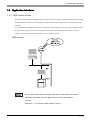
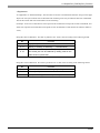
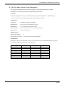
1.4.1 DDE function Outline
The DDE (Dynamic Data Exchange) function can be used with your PC’s commercial applications (SCADA
or MMI software) and Excel, which supports the DDE client function that provides for program-less data
exchange.
Once a DDE link is established, Pro-Server monitors the internal data and, if a stored value changes, notifies
the client of the change. Pro-Server provides the client with the data being monitored when a read-out
request is received and writes the data when a write request is received.
DDE function
Excel’s client feature does not support data write, so the DDE’s write feature
cannot be used. When you write data by Excel, use the VBA Support
Function.
Reference → “3.5 Using the VBA Support Function”
1-11
1.4 Application Interfaces
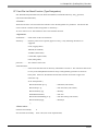
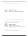
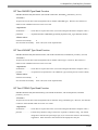
1.4.2 Simple DLL Function
The applications you create with Visual Basic or Visual C will request Pro-Server to read/write PLC data via
a GP. The function (API) for this is provided in the form of a DLL.
Simple DLL Connection
In environments where data transfer errors can frequently occur, be sure
your applications include a data transfer retry feature.
1-12
1.4 Application Interfaces
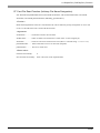
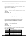
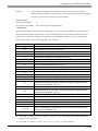
1.4.3 OPC Interface Function
Installing a Pro-Server OPC server allows you to use applications that have an OPC client function, such as
Intellution’s iFIX, as well as others.
The OPC interface function can only be used on a Windows NT, Windows 2000 or Windows XP system.
However, the security level of Windows 2000 must be set to the same as that used by Windows XP. For
setting information, see Appendix 6 Changing Windows XP Security Levels.
OPC Interface Design
1-13
1.4 Application Interfaces
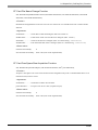
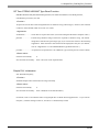
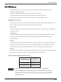
1.4.4 SRAM Backup Data Storage Function
The backup data in the SRAM of each GP can be easily transferred to the host PC. This SRAM backup
function is available for logging data, trend data, sampling data, alarm data (log/history), and others.
SRAM Backup Function
For details about the types of data you can transfer to the host PC, refer to the GP-PRO/PBIII for Windows
Tag Reference Manual.
Reference → “GP-PRO/PBIII for Windows Tag Reference Manual”
• You can assign alarm data (active) to the alarm block. By default, you can
take it into Pro-Server by designating Alarm Block1.
Reference → “3.6 Saving Backup Data in SRAM”
• Simultaneous upload of multiple types of data from a single GP is not
possible.
* You cannot use this feature on Factory Gateway.
1-14
1.5 Provider Information Outline
1.5 Pr
ovider Inf
ormation Outline
Pro
Information
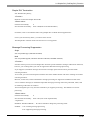
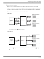
1.5.1 Providing Information to the Host
When a designated trigger’s condition(s) set by Pro-Studio is/are satisfied, PLC data is collected by the GP’s
resident 2-Way Driver and provided to the host PC. Therefore, since Pro-Server can temporarily store this
data in the PC’s memory, overall network traffic can be reduced.
For the procedure to register symbols in Pro-Server’s PC memory area, refer to 3.2 Registering Symbols.
Reference → “3.2 Registering Symbols”
1-15
1.5 Provider Information Outline
1.5.2 Providing Information between GPs
Even if your system lacks a host PC or Pro-Server, you can transfer the provider information setting file
setup in Pro-Studio to each GP. This then allows device data to be exchanged, via the GP, between PLCs on
the network, at a predetermined times or event, regardless of the brand of PLC used.
1-16
1.5 Provider Information Outline
1.5.3 Action Feature Overview
When the designated trigger conditions are fulfilled, an “Action” feature allows an application in a remote
PC on the network to be activated. Also, the program triggered by the Action feature is called the “Action
Contents”.
Action Features
Automatic Upload of Access Data (requires Microsoft Access)
Automatic Download of Access Data (requires Microsoft Access)
Writes Data to Excel Book (requires Microsoft Excel)
Download of Excel Recipe (requires Microsoft Excel)
Upload of GP Log Data
Automatic Upload of GP Filing Data
Automatic Download of GP Filing Data
Writes Data to E-Mail
Alarm Log (with Sound Alert Feature) (requires Microsoft Access)
Data Upload to Database (requires Microsoft Access/Excel)
Data Download from Database (requires Microsoft Access/Excel)
Start Application
Upload of GP JPEG Data
Writes Data to CSV File
Writes Data from CSV File
Create Report using Excel
Action Feature Overview
1-17
1.6 Overview of Data View
1.6 Over
vie
w of Data Vie
w
Overvie
view
View
When a designated trigger’s condition(s) set by Pro-Studio is/are satisfied, PLC data is collected by the GP’s
resident 2-Way Driver and saved on the server PC. Data View allows you to display the collected data on
Pro-face’s exclusive browser (GP-Viewer, Device View) in real-time. You can also change the data collection
condition or set the synchronization style with GPs (GP-Viewer only) using Data View. Device data of
multiple PLCs can be collected at the same time (Device View only).
In addition to the above, you can playback device data already collected on Data View (Playback Feature) or
on user-created applications (System Time Bar).
Collected device data can be viewed using a variety of tools, such as Device
View and GP-Viewer.
1-18
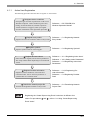
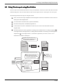
1.7 Configuring the System
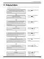
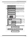
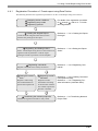
1.7 Configuring the System
The following explanation describes the steps you must follow to start Pro-Server, and assumes that GPPRO/PBIII is already installed on your PC.
Installing Pro-Server with Pro-Studio for Windows
Install Pro-Server with Pro-Studio for Windows on your
PC’s hard disk.
Starting GP-PRO/PBIII
Reference
Software”
“2.1 Installing the
Reference
“GP-PRO/PBIII
Operation Manual”
Start the GP-PRO/PBIII for Windows software.
Creating/Saving the screens with GP-PRO/PBIII
Open the GP-PRO/PBIII project file, create as many
project files as the number of the connected GPs, and save
the project files.
Starting Pro-Studio
Start Pro-Studio.
Setting/Saving the network project file with Pro-Studio
Open the network project file in Pro-Studio, make the
necessary settings, and save the file.
Transferring project files to your GPs
Transfer the project files, the network project file, and the
GP system setting to each connected GPs, one by one.
Performance Measurement
Measure the performance with the read performance
measuring tool.
Operation
Connect the GPs and the PC using a network cable. Start
Pro-Server on your PC.
Reference “GP-PRO/PBIII
Operation Manual”
Reference “2.2 Starting and
Exiting the Software”
Reference “2.2 Starting and
Exiting the Software”
“Chapter 3 Operation”
Reference
to GPs”
“5.1 Transferring Data
“GP-PRO/PBIII Operation Manual”
Reference
“6.3 Read
Performance Measuring Tool”
Reference
“2.2 Starting and
Exiting the Software”
“Chapter 6 Tools”
“Chapter 7 Data View”
1-19
Pro-Server
Fundamentals
2
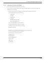
This chapter describes how to install this software. It also explains the procedures
for starting and exiting the software.
2.1
2.2
Installing the Software
Starting and Exiting the Software
2.3
Screen Item Names and Functions
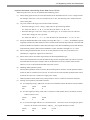
2.1 Installing the Software
2.1 Installing the Software
Install this software from the CD-ROM to your hard disk. The following explanation assumes that Windows
is already installed on your hard disk.
If you install Pro-Server V4.5 while GP-Viewer V1.0 remains on PC, a problem will occur when you install
GP-Viewer again. Be sure to uninstall GP-Viewer V1.0 and Pro-Server with Pro-Studio of the older version
from PC before installing Pro-Server V4.5.
• Prior to installing the software, exit all programs except the Pro-Server with
Pro-Studio for Windows Setup program. Be sure to quit all memoryresident programs (such as Virus detection software).
• Copying the master CD-ROM files to your hard disk does not install this
software. To be able to start this software, you must use the Setup program
(step 2 below).
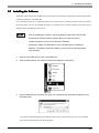
1.
Insert the CD-ROM into your PC’s CD-ROM drive.
2.
Click the [Start] button and, when the Start menu appears, select [Run].
3.
Type “D:/2WSetup.exe” and then click [OK]. (“D” represents the drive letter assigned to your
CD-ROM drive.)
The master CD-ROM supports the AutoPlay feature, which means inserting it into your CD-ROM
drive will automatically start the Setup program.
2-2
2.1 Installing the Software
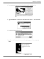
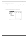
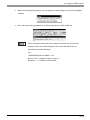
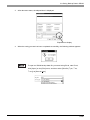
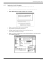
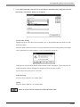
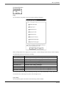
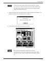
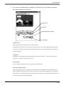
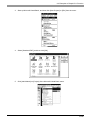
4.
The installation menu appears. Click the “Pro-Server with Pro-Studio Setup” bar.
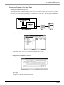
5.
Select which language you wish to use in the Setup program (English or Japanese) and click
“OK”.
6.
[InstalledShield Wizard] dialog will start.
7.
[Pro-Server with Pro-Server for Windows V4.5 Setup] dialog appears. Click on the [Next]
button.
2-3
2.1 Installing the Software
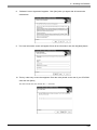
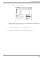
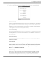
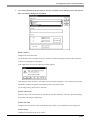
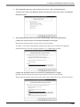
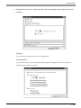
8.
“Software License Agreement” appears. Click [Yes] when you agree with all contents described here.
9.
The User Information screen will appear. Enter all the information and click the [Next] button.
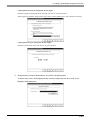
10. The key code entry screen then appears. Enter the code printed on the rear of your CD-ROM
case and click [Next].
The data entered must also include the “-” character.
2-4
2.1 Installing the Software
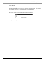
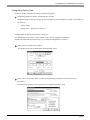
After this, follow the instructions displayed on the screen.
In addition to the Pro-Server with Pro-Studio for Windows V4.5 Setup Wizard, the “2WSetup.exe”
command can be used to start the following items.
• GP-PRO/PBIII 2-Way Driver Update
If you use the 2-Way Driver (Ver. 4.14 or older) older than GP-PRO/PB III for Windows Ver.7.0, be
sure to update the 2-Way Driver and set up GP. If you use Ethernet protocol with Factory Gateway,
you should also execute the update.
You can check the 2-Way Driver version on the status monitor.
Reference → “6.2 GP Status Monitoring”
• OPC Setup
The server and the client versions are available and support only Windows NT4.0, Windows 2000 and
Windows XP. Install the server version on the PC where you use Pro-Server and the client version on
the PC where you use client software.
• Tutorial
The tutorial uses HTML files to explain the installation, setup and usage of the Pro-Studio software.
• GP-Viewer Trial Version Setup
This is the trial version of “GP Viewer”. Install the GP-Viewer after Pro-Server installation is
completed. When you set up the trial version of “GP-Viewer”, you must have installed Microsoft
JAVA VM on your PC in advance. If not, you should obtain it from the Microsoft site.
• Setting the Factory Gateway Configration Tool
If you use this tool, you can perform the communication setup of Factory Gateway even without the
GP/PRO/PB III environment.
2-5
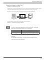
2.2 Starting and Exiting the Software
2.2 Star
ting and Exiting the Software
Starting
This section describes how to start and exit this software.
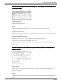
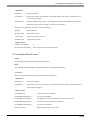
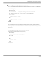
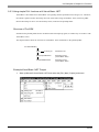
2.2.1 Using Pro-Studio
Starting Pro-Studio
The following explanation assumes that the Windows desktop is already displayed.
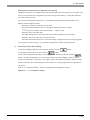
1.
Click [Start] button and when the Start menu appears, point to [Programs], [Pro-face] and
[Pro-Server with Studio], and select [Pro-Studio].
Double-clicking on the desired network project file (*.npj) in Windows Explorer automatically starts
Pro-Studio.
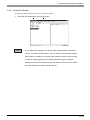
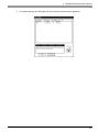
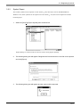
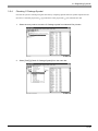
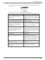
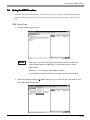
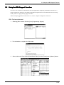
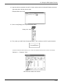
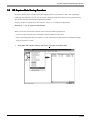
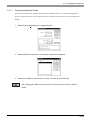
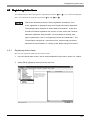
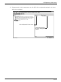
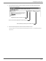
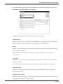
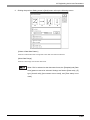
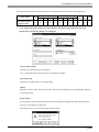
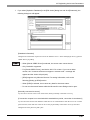
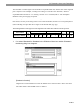
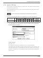
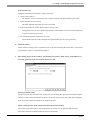
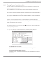
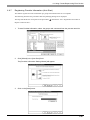
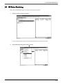
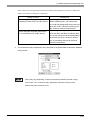
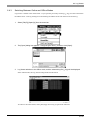
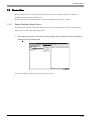
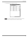
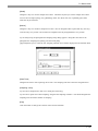
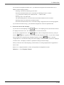
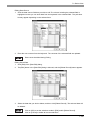
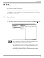
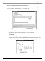
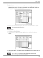
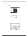
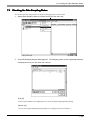
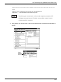
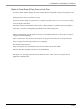
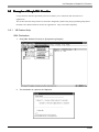
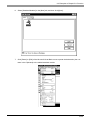
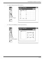
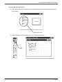
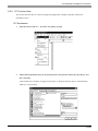
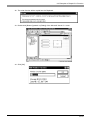
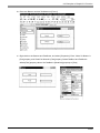
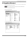
2.
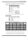
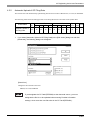
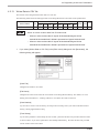
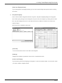
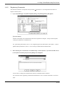
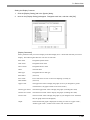
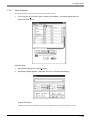
The program’s main window will appear. The left-side window shows a list of network entry
node GPs; the right-side window shows the symbols registered for each GP. Use this screen
to enter a variety of settings to configure your system.
2-6
2.2 Starting and Exiting the Software
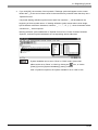
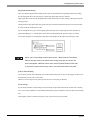
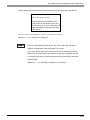
• Starting Pro-Studio automatically starts Pro-Server. Pro-Server resides in
memory and its indicator appears on the right side of the taskbar.
• Quitting Pro-Server automatically exits Pro-Studio as well.
To start Pro-Server only, click the [Start] button and, when the Start menu
appears, point to [Programs], [Pro-face] and [Pro-Server with Studio] and
then click on [Pro-Server].
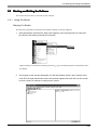
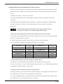
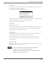
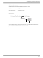
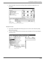
Creating a Network Project File
A network project file (*.npj) stores information such as the network entry nodes, symbols, and provider
information settings.
Creating a New Network Project
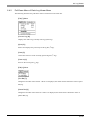
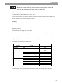
The following explains how to open a window and create new network projects.
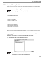
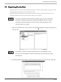
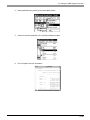
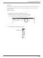
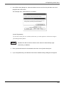
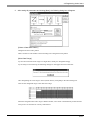
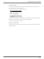
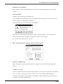
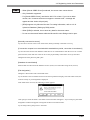
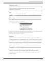
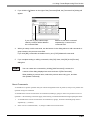
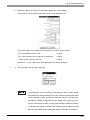
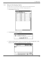
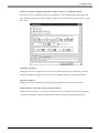
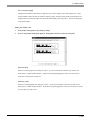
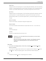
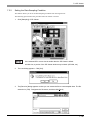
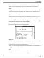
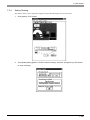
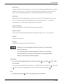
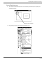
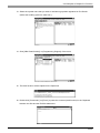
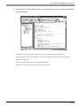
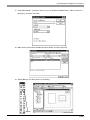
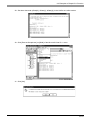
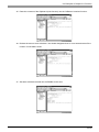
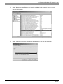
1.
Select [New(N)] in the [File(F)] menu.
2-7
2.2 Starting and Exiting the Software
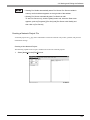
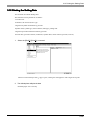
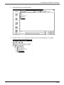
Opening/Saving a Network Project File
The following procedures explain how to open, close, and save a network project file. Before you proceed,
open the Pro-Studio main window.
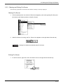
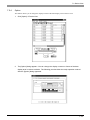
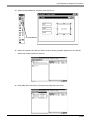
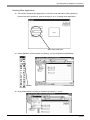
Opening a Network Project File
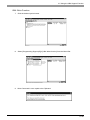
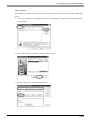
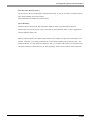
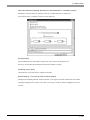
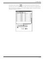
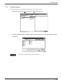
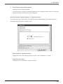
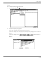
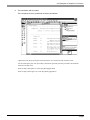
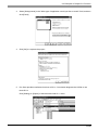
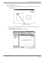
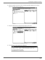
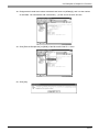
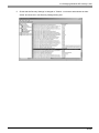
1.
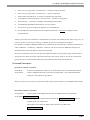
In the program’s main window, click [Open(O)] in the [File(F)] menu.
2.
Select the file you wish to open, and click [Open(O)].
3.
The file opens.
2-8
2.2 Starting and Exiting the Software
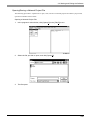
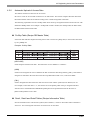
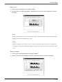
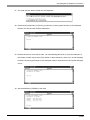
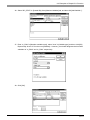
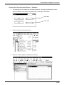
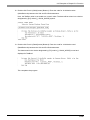
Saving a Network Project File
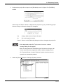
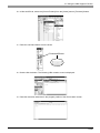
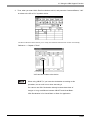
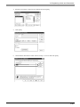
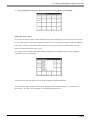
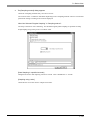
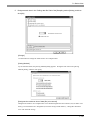
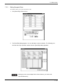
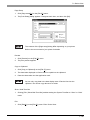
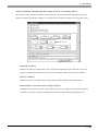
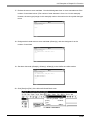
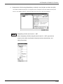
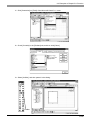
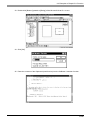
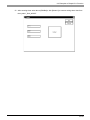
1.
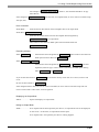
In the program’s main window, click [Save(S)] or [Save as(A)] in the [File(F)] menu.
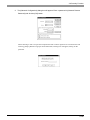
2.
If you have selected [Save(S)], the file is saved by overwriting the existing contents. If you have
selected [Save as(A)], in the following dialog box, save the file with a new file name.
2-9
2.2 Starting and Exiting the Software
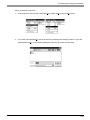
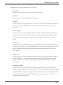
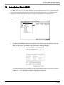
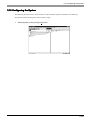
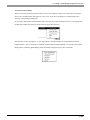
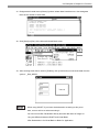
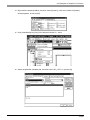
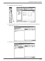
2.2.2 Exiting Pro-Studio
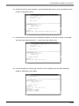
The following describes the procedure for exiting Pro-Studio.
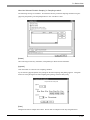
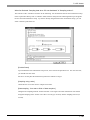
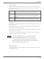
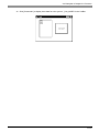
1.
Click [Exit Pro-Studio(X)] in the [File(F)] menu.
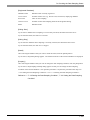
• If you change the settings of a currently open project and then attempt to
close it, you will be asked whether or not to save the new settings. Clicking
[Yes] saves the settings by overwriting the existing contents, and then exits
Pro-Studio. Clicking [No] exits Pro-Studio without saving the changes.
• Exiting Pro-Server automatically closes Pro-Studio. To be sure to terminate
all communication, be sure to exit Pro-Server.
2-10
2.2 Starting and Exiting the Software
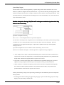
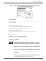
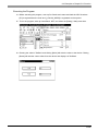
2.2.3 Starting and Exiting Pro-Server
The following explanation assumes that the Windows desktop is already displayed.
Starting Pro-Server
1.
Click the [Start] button and, when the Start menu appears, point to [Programs] [Pro-face] and
[Pro-Server with Studio], and then click [Pro-Server].
2.
While Pro-Server is running, the Pro- Server icon appears on the right side of the task tray.
Starting Pro-Studio automatically starts Pro-Server.
Exiting Pro-Server
1.
To exit Pro-Server, right-click on the Pro-Server icon on the right side of the task tray.
2-11
2.2 Starting and Exiting the Software
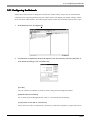
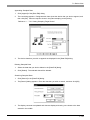
2.
When the shortcut menu appears, click [Exit].
• Exiting Pro-Server automatically exits Pro-Studio.
• If an application uses Pro-Server as a DDE client, an alarm message
will appear before you exit this software.
• An alarm message dialog will appear when you try to exit Pro-Server
while it is collecting data.
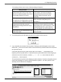
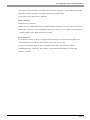
• If the OS is shutdown while a Pro-Server Action feature (See Chapter 4
Action Items) is running, the dialog [This program is not responding] may
appear. (The dialog shown below is from Windows 2000 Professional.)
If it does appear, the OS will not shut down until the dialog box is closed.
Please pay careful attention to this point when performing a remote OS
shutdown.
2-12
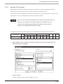
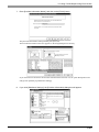
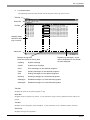
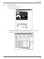
2.3 Screen Item Names and Functions
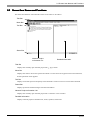
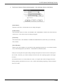
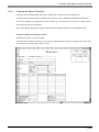
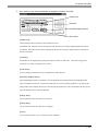
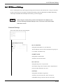
2.3 Screen Item Names and Functions
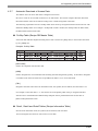
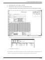
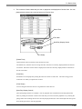
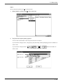
The names and functions of Pro-Studio’s main screen items are as follows:
Title Bar
Menu Bar
Tool Bar
Status Bar
Network Project
Information List
Detailed Information
Title Bar
Displays the currently open network project file (*. npj)’s name.
Menu Bar
Displays the menu to be used to operate Pro-Studio. Use the mouse or keypad to select a desired menu,
and the pull-down menu appears.
Tool Bar
Displays icons that represent frequently used commands. Click on an icon to execute that command.
Status Bar
Displays operation-related messages and other information.
Network Project Information List
Displays the currently open network project file’s contents in a tree structure.
Detailed Information
Displays network project information list, nodes, symbols, and actions.
2-13
3
Operation
This chapter describes how to register various types of system information.
3.1
3.2
Registering Network Entry Nodes
Registering Symbols
3.3
3.4
Registering Provider Data
Using the DDE Function
3.5
3.6
Using the VBA Support Function
Saving Backup Data in SRAM
3.7
3.8
Device Data Backup and Restoration
GP Capture Data Saving Function
3.9 Security Function
3.10 Configuring the System
3.11 Configuring the Network
3.12 Printing the Setting Data
3.13 Other Instructions
3.1 Registering Network Entry Nodes
3.1 Registering Netw
ork Entr
y Nodes
Network
Entry
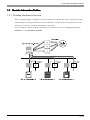
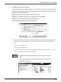
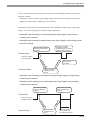
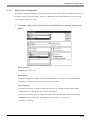
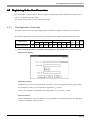
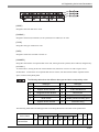
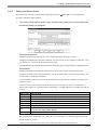
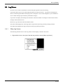
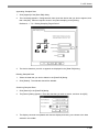
3.1.1 Registering a Network Node
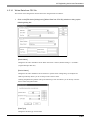
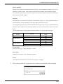
The procedure for entering the node name, IP address, sub net mask, gateway, and PLC type information is
described below. The node name can be the same as the project file name with the PLC type automatically
determined by selecting GP-PRO-PB III’s project file (*.prw). To transfer provider data from a GP to the
PC, you must first register the PC as a network entry node.
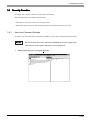
The following description assumes that Pro-Studio’s main window is open.
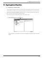
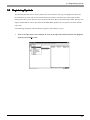
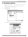
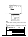
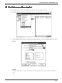
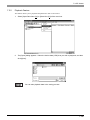
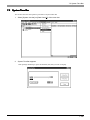
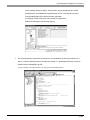
1.
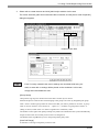
Select [Register Node] in the [Edit(E)] menu.
You can right-click on the network entry node and select [Register Node] from the shortcut menu that
appears.
3-2
3.1 Registering Network Entry Nodes
2.
The [Register Node] window will appear.
Change [Node Name]. The default value is “GP*”. It is recommended to use the node name
that you can easily understand what is connected. When you change [Node Name], you must
follow restrictions described below.
Select the equipment that you register here for [PLC Type].
Designate [IP Address] so that it does not overlap with any other addresses.
Designate [SubnetMask] and [Gateway] only when required.
Enter the necessary data for all the items and click [OK].
A [Node Name] indicates a name of a communicator (usually, GP or PC) that performs communication activities on the network, which is usually a GP unit or personal computer. This node name
must:
• Consist of 31 characters or less.
• Begin with an alphabetic letter.
• Use alphanumeric characters (no differentiation between upper and lowercase letters), _ (underscore), ~ (tilde), and 80h or higher ASCII characters.
• Select the GP-PRO/PBIII for Windows project file (.prw) you wish to
use.
• You may also drag the file from Windows Explorer and drop it in the
Pro-Studio’s main window.
3-3
3.1 Registering Network Entry Nodes
The character string data mode is set according to the data storage order of
the used PLC. Normally, it is automatically set to the mode according to the
data storage order of the used PLC, therefore, you do not have to change it.
When you changed the setting of the character string data mode, you must
reset the character string data mode in the project file (*.prw) of GP on the
entry node side to the value designated here.
Reference → “GP-PRO/PB III for Windows Operation Manual GP Setup”
(I) Device Storage
(II) Byte LH/HL
(III) Word LH/HL
Character String
Order of Data
Storage Order in
Storage Order in
Data Mode
Word
Double-Word
Store from the front
LH
data
HL
Store from the end
LH
data
HL
LH
4
HL
2
LH
5
HL
1
LH
6
HL
7
LH
8
HL
3
The detailed settings of the selected network entry node are shown in the right-side window.
3.
After registration is completed, the registered node name will be added to the network node list.
If you wish to change a node (topic)’s data after it has been registered, simply right-click on the topic to
bring up a list of selections. From these, click either the [Edit Node] or [Delete Node] selections, or,
from the menu bar, click the [Edit] menu’s [Edit Node] or [Delete Node] items.
Clicking either
or
allows you to edit the registered nodes, in
the order of registration. When
is clicked on while the last regis-
tered node is highlighted, the “edit” mode will change to the “add” mode
and a new node will be added.
3-4
3.1 Registering Network Entry Nodes
3.1.2 Searching a Network Node
You can create a list of the GPs and PCs that are active in the network and immediately register any node
that is not in the network project file (*.npj). (The following description assumes that Pro-Studio’s main
window is open)
1.
Click [Search Active Node] in the [Tools(T)] menu.
Use this function to automatically search for the nodes connected to the network. It allows you to
register network nodes easily, since information such as the PLC type is retrieved and entered
automatically by Pro-Studio.
2.
The following dialog box will appear. To register any of the detected nodes, click first the [Node
Status] “Non-Entry” text, then the [Entry] button.
3-5
3.1 Registering Network Entry Nodes
3.
The following dialog box will appear to show that the node has been registered.
3-6
3.2 Registering Symbols
3.2 Registering Symbols
The following describes how to enter symbol name, device address, data type, and polling time data. The
device address you enter will be converted internally into a device code that can be used inside the GPs.
Polling time refers to how often Pro-Server polls the GP when data is read out through a DDE. You may also
import symbols that have been exported from GP-PRO/PBIII. Symbols can be registered for each network
entry node.
(The following description assumes that the program’s main window is open)
1.
Click on the right section of the window. Or, click on the right-side window and then click [Register
Symbol] in the [Edit(E)] menu.
3-7
3.2 Registering Symbols
2.
The [Register Symbol] window then appears. Enter all items and click [OK].
A symbol must
· Consist of 31 characters or fewer.
· Begin with an alphabetic letter.
· Use alphanumeric characters (no differentiation between upper and lowercase letters), _ (underscore), ˜
(tilde), and 80h or higher ASCII characters.
[Create from Address]
After selecting a Device Address, click on this button to automatically register the Device Address as
a symbol.
[Global Symbol]
Clicking on the Global Symbol check box automatically designates the same symbol for all of the
registered network nodes. This setting will be ignored if the device specified by the symbol does not
exist in the registered network nodes.
[Data Type]
Designate the data type of the symbol to be registered. Data types that you can designate are 12 types
shown in the table below.
Data Type
Data Type
Bit
BCD 16 Bits
16 bits signed decimal
32 bits signed decimal
16 bits unsigned decimal
32 bits unsigned decimal
16 bits hexadecimal
32 bits hexadecimal
Data Type
BCD 32 Bits
Single precision floating
point
Double precision floating
point
Character string
3-8
3.2 Registering Symbols
For setting/editing C-Package symbol and GLC, there are following restrictions to the setting of these
symbols’ formats.
Device Format Designated
by Symbols
Word Type
Notes
Changeable Format
Formats other than Bit
You cannot select an
type.(signed/unsigned 16/32
unchangeable format.
bits, hexadecimal, BCD, single
precision floating point,
double precision floating
point, character string)
Bit Type
Supports only the Bit format.
32 Bits Word Type
Supports only the 32 bits
(GLC symbols only)
format.(signed/unsigned 32
bits, hexadecimal, BCD, single
precision floating point)
[Polling Time]
The data here shows an example of data being read out via the DDE feature.
Under certain conditions the polling time used for collecting or writing data for each symbol,
distributing data and monitoring devices may not be performed. These conditions include the number
of currently registered GPs, number of Tags used on each screen sent, type of PLC connection, and
number of other currently open Windows applications. Entering “0” will allow the system to operate
at maximum speed. Use this value as a benchmark when entering other values to “fine-tune” your
system.
3.
When all settings are selected, the detailed settings appear in the right-side window.
If you wish to change a symbol’s data after it has been registered, simply right-click the symbol name
(right-window) to bring up a list of selections. From these, click on either the [Edit Symbol] or [Delete
Symbol] selections, or, from the menu bar, click on the [Edit (E)] menu’s [Edit Symbol] or [Delete
Symbol] items.
3-9
3.2 Registering Symbols
3.2.1
Importing Symbols
This section describes how to import symbols. The usable symbol data include symbols imported from GPPRO/PBIII (*.lbe), symbols exported from other network project file (*. 2ws), and comment data (*.csv)
from GPP function software for Windows (Mitsubishi Electric).
1.
Click [Import Symbol] in the [Tools(T)] menu.
You can also right-click the registered network node and click [Import Symbol] on the shortcut menu.
2.
The following dialog box will appear. Select the file type to be imported. Then, click a desired
file and then the [Open] button.
3.
The following dialog box will appear, and the designated symbol will be imported.
3-10
3.2 Registering Symbols
3.2.2
Symbol Export
The created symbols can be exported in a file format (*. lbe) that can be used on GP-PRO/PBIII for
Windows. Also, these symbols can be exported in a file format (*. 2ws) that can be imported to another
network project.
1.
Select the [Tool(T)]-[Export Symbol] from the Menu Bar.
Right-clicking on a desired node can also be used to select [Export Symbol].
2.
The following dialog box will appear. Designate the format and name of the file to be exported
and click [Export].
3.
The following dialog box will appear and the symbol will be exported.
3-11
3.2 Registering Symbols
3.2.3
Importing C-Package Symbol
For Pro-Server to access to the C-Package symbol (Special Protocol symbols and GLC symbols (variables)
registered on GP-PRO/PB III), you should import Special Protocol symbols and GLC symbols defined in the
GP-PRO/PB III for Windows project file (*.prw) to the network project using Pro-Studio.
When importing screen definition symbols via Pro-Server, those symbols must
be used on the same version screen editor software used to create them.
The following 12 kinds of protocols require symbol registration for drawing data.
• MITSUBISHI MELSECNET/10
• OMRON SYSMAC-CS1 (ETHER)
• HITACHI HIDIC H (ETHER)
• Siemens S7-200 via MPI
• Siemens S7-300/400 via MPI
• SIEMENS S7-300/400 (ETHER)
• AB Slc500 DH485
• AB ControlLogix (EtherNet/IP)
• Allen Bradley SLC5/05 (ETHER)
• Schneider TSX via UNI-TELWAY
• Schneider Modbus TCP (ETHER)
• Schneider Modbus RTU 1:n comm.
These 12 kinds of protocols are regarded as “Special Protocol” on Pro-Server, and the protocol description
on Pro-Server is shown as “OMRON SYSMAC-CS1 (ETHER) *”.
For Pro-Server to support “Special Protocol”, GP-PRO/PB III for Windows for creating the project file
(*.prw) is required.
Reference → “GP-PRO/PB III for Windows Operation Manual” Symbol Editor
1.
Select the target node from the Network Entry Node list.
The “Import GLC Symbol” menu from Pro-Server ver.4.0 or earlier has been
integrated into the “Import C-Package Symbol” menu.
3-12
3.2 Registering Symbols
2.
Designate the project file to import in the [Edit Node] screen’s [Project File (PRO/PB3)]
window.
When using the "Browse" button to designate the project file (*.prw), the following project
filename change confirmation dialog box will appear.
Yes
:Change Node name to Project file name.
No
:Do not change Node name.
Cancel :Returns to the [Edit Node] dialog box without changing the project file.
• If the designated project file (*.prw) name is incorrect, an alarm
message dialog box will appear.
• When the designated GP-PRO/PBIII project file has been changed, all
of that node's previously registered symbol’s address display section
GLC Symbols/Screen Creation Definition Symbols that have become
symbols are automatically deleted.
3.
Select the [Tools(T)]-[Import C-Package Symbol] command.
3-13
3.2 Registering Symbols
If the setting contents are incorrect, following dialogs will appear.
Dialog Contents
XXX (number) undefined Screen Editor
Symbols have been used on the screen. If
they are not defined symbols, they cannot
be imported (used) by Pro-Server.
Cannot perform processing because the
PLC type set on Pro-Server does not match
to that defined in the PRO/PB III project file.
Cannot find the project file to be imported.
Designate the project file using the
[Edit(E)]-[Edit Node]-[PRO/PB III Project
File] fearture.
Cannot execute not in administrator mode.
Please login again.
Solution
To import (use) the Screen Editor Symbols
in Pro-Server, you must use drawing
software data (only the Screen Editor
Symbols used on the screen can be
imported).
Set the correct PLC type in the [PLC Type]
field of the [Edit Node] dialog box in
procedure 2.
Designate the project file (*.prw) using the
[PRO/PB III Project File] field of the [Edit
Node] dialog box in the procedure 2. If the
designated project file (*.prw) does not
exit, re-designate the correct project file.
Login again in administrator mode, and reimport the data.
4.
The following dialog box will appear and the GLC symbols will be imported.
5.
If you click [OK], the contents of the imported C-Package symbol will appear on the screen.
Nodes with “*” at the end of those names in the network entry node list means that it imported
the “Special Protocol”.
If imported Special Protocol symbol names start from numbers, “_” will be added in the
beginning of those symbol names. If Special Protocol symbol names also include single-byte
characters other than characters, numbers, “_”, “~”, “.”, “#”, “(” “)”, those characters will be
converted to “_” when imported.
The special protocol symbol cannot display the device address. Therefore, all special protocol
symbols are displayed as “Screen Creation Definition Symbols”. For other symbols, corresponding device addresses are displayed.
3-14
3.2 Registering Symbols
• When importing C-Package symbols, be sure to send the Network Project file to
the GP/GLC/Factory Gateway.
• When using Pro-Control Editor to Add or Delete GLC variables (GLC symbols),
be sure to import the C-Package symbols again.
When GLC variables are added or deleted, the related variable’s information is
remapped to GLC memory. If old mapping information is used when Pro-Server
accesses the GLC, it can result in a unit operation error.
• Do not import C-Package symbols while a Data View is performing Data
Sampling. Prior to importing symbol data, be sure to close all Data Views and
use the [Data View (D)] screen’s [Data Sampling Status] dialog box to confirm
that all data sampling is stopped.
3-15
3.2 Registering Symbols
3.2.4
Checking C-Package Symbol
Check if the system is running using the same file by comparing Special Protocol symbols imported to the
Pro-Server’s network project file (*.npj) with those in the project file (*.prw) transferred to GP.
1.
Select the entry node to check the C-Package symbol from Network Entry Nodes.
2.
Select [Tool(T)]-[Check C-Package Symbol] from the menu bar.
3-16
3.2 Registering Symbols
3.
The checking process is executed and the following dialog box will be displayed when no
errors exist.
If the checking result includes errors, following dialog boxes will appear.
Solution
Dialog Contents
The C-Package symbol may have been
If you wish to update the C-Package
changed. Do you want to import the C-
symbol and continue checking, click [Yes].
Package symbol?
If you continue checking without updating
it, click [No].
The C-Package symbol may not have been Transfer the project file (*.prw) to the entry
transferred to the designated entry node.
node using C-Package.
Cannot execute the process because the
The “PLC Type” setting is incorrect.
PLC type set on Pro-Server does not
Change the node’s PLC type to the same
match that defined in the PRO/PB III
as the “PLC Type” in the project file
project file.
(*.prw).
Cannot find the project file on the import
The project file (*.prw) may not have been
source. Designate the project file on the
designated, or the designated project file
import source to [Edit(E)]-[Edit Node]-
(*.prw) does not exist. Change the project
[PRO/PB III Project File].
file designated by the entry node to the
appropriate one.
Cannot execute not in administrator mode.
Login again in administrator mode, and re-
Please login again.
import the data.
Cannot connect to the designated entry
Cannot connect to the entry node is
node.
usually due to such a communication
setting problem (the IP address is incorrect
or a cable is disconnected). Check the IP
address and all communication cables.
Cannot acquire symbol information from
Failed to acquire information from the
the designated entry node.
symbol file.
Cannot execute the process because the
You cannot check an entry node which
designated entry node does not support
does not support online update.
online upload.
3-17
3.2 Registering Symbols
4.
If you click [OK], the contents of the imported C-Package symbol will appear on the screen.
Nodes with “*” at the end of those names in the network entry node list mean that they use a
“Special Protocol”.
If imported drawing definition symbol names start from numbers, “_” will be added in the
beginning of those symbol names. If drawing definition symbol names also include singlebyte characters other than characters, numbers, “_”, “~”, “.”, “#”, “(“ ”)”, those characters will be
converted to “_” when imported.
Drawing definition symbol addresses of “Special Protocol” are “Screen Creation Definition
Symbols”, and other symbol addresses are corresponding device addresses.
System Variables can be set to “Show” or “Hide” mode. System Variables can be set to “Show” or “Hide” by clicking the
icon, or via the
[View(V)] menu’s [System Variables(V)] setting screen.
After a Symbol is imported, the System Variable is set to “Hide” mode.
3-18
3.3 Registering Provider Data
3.3 Registering Pr
ovider Data
Pro
Designate data that GP of each node provides periodically or when the trigger condition is satisfied, as well
as data storage location for GP or PC, which receives data.
Designated provider information becomes effective by transferring the network project file to GP. The
following description starts from the state after the main screen is opened.
If constant is selected in the [Provider Information], when you open the network
project file in a different environment (Japanese OS/English OS), the contents
of [Symbol Name] are displayed incorrectly. Please make the settings of [Provider Information] once again.
1.
Select the registered entry node, and then select [Edit(E)]-[Register Provider Information] from
the menu bar.
• The maximum number of provider information that can be registered is 350.
• You can also select [Register Provider Information] by right clicking the provider
information list.
2. The [Provider Node] dialog appears. Select the data provider source node, and then click [OK].
3-19
3.3 Registering Provider Data
3.
The [Provider Information] dialog box appears. Perform necessary settings in [Providing
Condition], [Provider Completion Settings], [Receive Alert Settings], [Detailed Settings],
[Provider Node] and [Consumer Node(s)], and then click [OK].
For provider node symbols and consumer node symbols, only the same format can be selected.
Pr
oviding Condition Tab
Pro
Following items are displayed by selecting the providing condition.
Setup Items
Power ON
X
X
X
Processing
after Providing
X
On Time
X
O
X
X
Condition
Symbol Name
Time/Interval Setup
Designated Interval
Remarks
Interval
X
O
X
Rewrite Trigger
O
O
X
Status ON
O
O
X
Status OFF
O
O
X
Upper Edge Trigger
O
O
*1
Lower Edge Trigger
O
O
*2
X: Setting disabled
O: Setting enabled
: Option (need to be set when check boxes are checked)
*1 If you designate “Upper Edge Trigger” and check “OFF Time After Providing”, the device
designated by the symbol name is set to OFF (0) when the providing process is completed.
*2 If you designate “Lower Edge Trigger” and check “ON Time After Providing”, the device
designated by the symbol name is set to ON (1) when the providing process is completed.
3-20
3.3 Registering Provider Data
Each item on the [Providing Condition] tab are as following:
[Power ON]
Provides only once when the power of provider node is turned ON.
[ON Time]
Provides only once at the designated time. Enter the time.
[Interval]
Provides according to the designated interval. If you wish to limit the period, check [Limit Period] and
enter the period. Trigger condition becomes effective only during that period. Enter the providing
interval (ms).
[Rewrite Trigger]
Provides when a device value designated a symbol is rewritten. Select the symbol to designate from
the pull-down list. If you wish to limit the period, check [Limit Period] and enter the period. Trigger
condition becomes effective only during that period. Enter also the interval (ms) to check device
rewrites.
[Status ON]
Provides when a device value designated by a symbol is other than zero. Select the symbol to designate from the pull-down list. If you wish to limit the period, check [Limit Period] and enter the period.
Trigger condition becomes effective only during that period. Enter also the interval (ms) to check
device ON/OFF.
[Status OFF]
Provides when a device value designated by a symbol is equal to zero. Select the symbol to designate
from the pull-down list. If you wish to limit the period, check [Limit Period] and enter the period.
Trigger condition becomes effective only during that period. Enter also the interval (ms) to check
device ON/OFF.
[Upper Edge Trigger]
Provides when a device value designated by a symbol changes from zero to values other than zero.
Select the symbol to designate from the pull-down list. If you wish to limit the providing period, check
[Limit Period] and enter the period. Trigger condition becomes effective only during that period. After
providing this device, check [OFF After Providing] to turn it OFF automatically. Also, enter the
interval (ms) to check device values.
3-21
3.3 Registering Provider Data
[Lower Edge Trigger]
Provides when a device value designated by a symbol changes from values other than zero to zero.
Select the symbol to designate from the pull-down list. If you wish to limit the providing period, check
[Limit Period] and enter the period. Trigger condition becomes effective only during that period. After
providing this device, check [ON After Providing] to turn it ON automatically. Also, enter the interval
(ms) to check device values.
Pr
ovider Completion Settings Tab (This tab’
s settings are enab
led onl
y when the 2-W
ay
Pro
tab’s
enabled
only
2-Wa
Driver is Ver
.4.10 or later)
er.4.10
[Provider Completion Device]
Sets “0” or “1” to the designated device at provider completion.
If you wish to reset the provider completion device automatically by the 2-Way system when providing
conditions are reset, check [Automatic Device Reset after Reset of Provider Settings]. [Provider
Completion Device] supports all data types. If [Provider Completion Device] is not designated,
nothing will be set.
If provider completion device write failed 3 times continuously, an error occurs.
When one of condition a through c is satisfied, provider is regarded as being completed.
a : If the “Reply Check” option in the [Detailed Settings] tab is checked, this feature indicates that a
response was received from all providers, or indicates that polling termination was performed after
the [Provider Timeout Time] elapsed and no response was received.
b : If provider is executed with “Reply Check” unchecked in the [Detailed Settings] tab, provider is
regarded as being completed when having received replies from all provider destinations.
c : When condition a is satisfied and a [Retry] value has been entered in the [Detailed Settings] tab,
this condition indicates polling termination was performed after the Retry was performed the
specified number of times and no response was received.
Entering the following settings in the [Providing Condition] tab will disable the [Provider Completion
Device] feature.
• Checking [OFF After Providing] of [Upper Edge Trigger] or [ON After Providing] of [Lower Edge
Trigger] in the [Providing Condition] tab.
3-22
3.3 Registering Provider Data
You can set the [Automatic Device Reset after Reset of Provider Settings] checkbox only under the
following condition.
• When [OFF After Providing] of [Upper Edge Trigger] or [ON After Providing] of [Lower Edge
Trigger] in the [Providing Condition] tab are not checked.
The following timing charts describe 4 kinds of provider completion conditions using “Upper Edge
Trigger” and “Lower Edge Trigger” in the [Providing Condition] tab.
• When [OFF After Providing] is checked while [Upper Edge Trigger] in the [Providing
Condition] tab is selected:
• When [ON After Providing] is checked while [Lower Edge Trigger] in the [Providing Condition] tab is selected:
Application program
recognizes provider
completion when provider
condition device is reset.
Set providing condition
device (via application
program).
Provider Node
Device Providing
Condition Data
Re
ply
ata
ed
vid
Pro
Consumer Node
Reset by the system
after provider
completion
Writes provided
data/Executes an
action.
• When [OFF After Providing] is unchecked while [Upper Edge Trigger] in the [Providing
Condition] tab is selected:
• When [ON After Providing] is unchecked while [Lower Edge Trigger] in the [Providing
Condition] tab is selected:
Set providing condition
device (via application
program).
Reset providing condition
device (via application
program).
Provider Node
Writes provided
data/Executes an
action.
Re
ata
ed
vid
Pro
Consumer Node
ply
Device Providing
Condition Data
Wait for more than 2
check interval until
executing next provider.
3-23
3.3 Registering Provider Data
• When [Provider Completion Device] is “designated” and [Automatic Device Reset after Reset of
Provider Settings] is unchecked while [Upper Edge Trigger] is selected in the [Providing Condition] tab:
• When [Provider Completion Device] is “designated” and [Automatic Device Reset after Reset of
Provider Settings] is unchecked while [Lower Edge Trigger] is selected in the [Providing Condition] tab:
Reset both of providing
condition device and provider
completion device (via
application program).
Set providing condition
device (via application
program).
Device Providing
Condition Data
Re
e data
Provid
Device Providing
Completion Data
An application program
recognizes provider completion
when provider completion
device is reset.
ply
Provider Node
Consumer Node
Set by the system after
provider completion
Writes provided
data/Executes an
action.
Wait for more than 2
check interval until
executing next provider.
• When [Provider Completion Device] is “designated” and [Automatic Device Reset after Reset of
Provider Settings] is checked while [Upper Edge Trigger] is selected in the [Providing Condition] tab:
• When [Provider Completion Device] is “designated” and [Automatic Device Reset after Reset of
Provider Settings] is checked while [Lower Edge Trigger] is selected in the [Providing Condition] tab:
Set providing condition
device (via application
program).
Device Providing
Condition Data
vide
Pro
Device Providing
Completion Data
An application program
recognizes provider
completion when provider
completion
device is reset.
data
Consumer Node
Rep
ly
Provider Node
Reset providing
condition device
(via application
program).
If both of providing
condition device and
provider completion
device have been reset,
an application program
can set providing
condition device for the
next provider.
Writes provided
data/Executes an
action.
Set by the
system after
provider
completion
The system resets
provider completion
device when it
recognizes provider
condition device to
have been reset.
3-24
3.3 Registering Provider Data
The following shows timing among [Providing Condition Device], [Provider Completion Device],
[Provider Result Storage Bit Device] (described later), [Provider Error Code Storage Device] (described later), [Consumer IP Address Storage Device] (described later) and [Provider Receive Alert
Device] to be set in the [Receive Alert Settings] tab.
Set providing condition
device (via application
program).
Device Providing
Condition Data
Application program checks if
provider was executed successfully
from provider result when provider
completion device has been set.
Device Providing
Completion Data
Provider
completion device
is set after saving
provider result.
Provider Node
Consumer Node
Reply
e data
Provid
Provider Result
Storage Bit
Provider Error Code
Consumer IP
Address Storage
Writes provided
data/Executes an
action.
If provider reply is an error,
the provider result storage bit
will be set, the error code will
be set to the provider error
code, and the consumer IP
address will be set to the
consumer IP address storage.
If the contents of the
response are successful, the
provider result storage bit will
be reset.
Device Providing
Receive Alert Data
Provider receive alert
device is set after the
system writes provided
data.
Provider receive
alert device is reset
by an application
program at the
consumer node.
[Provider Result Storage Bit Device]
Sets “0” if provider result is normal, and “1” if not. Data will be overwritten every time provider is
received. You can set only symbols with the “Bit” format.
[Provider Error Code Storage Device]
Stores error codes when provider result is abnormal. You can set only symbols with the “16 Bits” or
the “32 Bits” format.
[Consumer IP Address Storage Device]
Stores the IP address of the provider destination when an provider error occurs. You can set only
symbols with the “32 Bits” format.
3-25
3.3 Registering Provider Data
Receive Aler
s settings are enab
led onl
y when the 2-W
ay Driver
Alertt Settings Tab (This tab’
tab’s
enabled
only
2-Wa
is Ver
.4.10 or later)
er.4.10
[Consumer Node]
Displays network entry nodes.
[Row]
Displays the number of provider record. You can set receive alert per provider record.
[Receiver Symbol Name]
Displays device symbols names to receive provider. Symbol names set on entry nodes are displayed.
[Provider Receive Alert Device]
Designate device to set to “1” (ON). Select device from the pull-down menu.
This device is set before provider completion device is set.
For details of set/reset timing between this device and other device, refer to the timing chart in the
previous page.
Detailed Settings Tab (This tab’
s settings are enab
led onl
y when the 2-W
ay Driver is
tab’s
enabled
only
2-Wa
Ver
.4.10 or later)
er.4.10
[Provider Type]
Select the provider type.
[Reply Check]
Select if the replay for provider completion should be checked. The maximum waiting time is the
provider timeout time.
[Retry]
Designates the Retry count when the “Reply Check” option is checked. Enter a numeric value from 0
to 32.
3-26
3.3 Registering Provider Data
[Provider Timeout Time]
Sets the provider timeout time. If you wish to change the provider timeout time to desired numbers,
uncheck [Use Provider Timeout Time from Network Settings].
Provider timeout time designated per the network project file (*.npj) with Pro-Server V4.0 or older can
be set per provider sheet. If you uncheck [Use Provider Timeout Time from Network Settings], you
can designate provider timeout time per provider sheet individually.
If provider is executed before provider destination GP is started such as more than one GP is started
simultaneously, an error is displayed on the provider destination GP. You can avoid unnecessary error
display by setting the number of retry.
If you use the system in the environment where communication errors frequently occur, you can avoid
unnecessary error display by setting the number of retry.
When a large volume of data is sent, the GP will not refresh its display whie data is being provided.
The volume of data which can be provided at one time differs depending on an area supported by PLC.
For the volume of data which can be provided at one time, refer to each PLC manual.
Moreover, symbols designated to provider nodes/consumer nodes depend on the maximum number of
data which can be provided. The following table shows the relationship between the maximum number
of data which can be provided and symbols to be designated.
Device Type
to Access
Bit Device
16 Bits
Device
32 Bits
Device
Format
Bit
Maximum Number of
Maximum Number of Maximum Number of Data
Data When Designating Data When Designating When Designating Other
Special Protocol Symbols Special Protocol Symbols Symbols to Provider/
to Provider Nodes
to Consumer Nodes
Consumer Nodes
255
1
16
Bit
255
1
16
16 bits
255
40
255
32 bits
Single precision
floating point
Double precision
floating point
Character string
127
20
255
127
20
255
63
10
255
255 (single byte)
80 (single byte)
255 (single byte)
Bit
255
1
255
32 bits
Single precision
floating point
Double precision
floating points
Character string
255
40
255
255
40
255
127
20
255
255 (single byte)
160 (single byte)
255 (single byte)
If you designate values exceeding those maximum numbers, the warning dialog will appear.
You can register 3 “Symbol Names” at maximum per “provider information”.
3-27
3.3 Registering Provider Data
If you select [String Fixed Number] in the [Symbol] field of the provider node, the count calculation
will be performed automatically only by entering a fixed number. Although you can change this count
to the larger number than the string number entered by a fixed number, do not change the number
calculated automatically to avoid unfixed data to be entered.
• The check interval is defaulted to “500” ms.
• The process after providing should be set to “Complete Process”. The
process is completed even when a providing error occurred.
If you designate the existing sheet name in the [Title] field of the [Provider Information] dialog,
the following dialog will appear.
Change the sheet name in the [Title] field to something new.
If you wish to change a node (topic)’s data after it has been registered, simply right-click on the topic
to bring up a list of selections. From these, click either the [Edit Node] or [Delete Node] selections, or,
from the menu bar, click the [Edit(E)] menu’s [Edit Node] or [Delete Node] items.
The contents of provider settings may affect system communication speed. In such a case, refer to “A.5
Optimizing Communication Speed” and change settings.
Reference → “A.5 Optimizing Communication Speed”
3-28
3.3 Registering Provider Data
3.3.1
Checking for Provider Data Errors
The following procedure explains how to check provider data. If, after registering provider data, you delete
the relevant symbol name or network node, or alter any symbol’s data type, an error message will appear. If
no errors are found in the provider data, the data’s file size when it is downloaded to the GP will be displayed. The file size shown in this dialog box reflects the amount of GP screen area used.
(The following description assumes that the program’s main window is open)
1.
Click the [Check Provider Information] item in the [Tools(T)] menu.
3-29
3.3 Registering Provider Data
2.
The following dialog box appears.
Although the program checks provider data automatically during saving, it will not display the file size.
In the following cases an error will occur:
After entering provider information,
· the data type of a symbol has been changed,
· a symbol name has been changed or deleted, or
· a node name has been changed or deleted.
If an error occurs, you will not be able to transfer the network project file (*.npj) to the GP.
DO NOT edit or delete a symbol, or that symbol’s designated provider node.
Maximum size of provider information data is 60 kbytes.
Rule of thumb
Base.........................................36bytes
Register Node..........................88bytes
Register Provide Information.....120bytes
3-30
3.3 Registering Provider Data
3.3.2
Action Items
Using the action item function, you can designate the desired action item(s) (called action item “contents”)
so that a Consumer (only a Windows OS personal computer) which has received provider information will
perform them.
You can start action items by setting the symbol name of the Provider node to the action name.
Action items must be set up, however, it is possible that they are not used during normal operation.
For a detailed explanation of action item functions, refer to “Chapter 4 Action Items”.
Reference → “Chapter 4 Action Items”
3-31
3.4 Using the DDE Function
3.4 Using the DDE Function
Pro-Server incorporates the DDE server function and therefore can exchange data with applications that
support the DDE client function. The following description assumes that the program’s main window is
open.
DDE: String Copy
1.
Click the desired symbol name.
• With Excel, you cannot use DDE to write data because Excel does not
support data writing as a DDE client. To write data to Excel, use the
VBA function.
Reference → “3.5 Using the VBA Support Function”
• If you use Windows XP, you cannot execute write using the DDE feature.
2.
Select [Programming Support(P)]-[DDE: String Copy]. Or, right-click the symbol name, and
then select [DDE: String Copy].
3-32
3.4 Using the DDE Function
3.
When the following dialog appears you can paste the copied string into any DDE-compatible
software.
4.
Here, the copied string is pasted into an Excel worksheet to create a DDE link.
When a symbol’s data is text and is copied to an Excel cell, only the first
character of the text will be displayed. In this case, edit that Excel cell
and add the required characters.
Ex.)
=PROSERVER|GP1!’ SYMBOL .*20’
Be sure to put “’ (quotation marks)” around “!”.
Reference → “A.1 DDE Function Details”
3-33
3.4 Using the DDE Function
Workaround Example 1 for Mass Data
Creating an LS Area inside your PC
When using the (data) distribution feature, the creation of an internal LS (Pro Server) area inside your PC
will allow you to read out data periodically via GP from one or more PLCs. The setting of the DDE feature
to read out collected data from the LS area will allow the data in the LS area to be refreshed faster.
1.
Call up the Register Node feature to register the host PC.
To Register a Node, refer to “3.1 Registering Network Entry Nodes”
2.
Designate the IP address for host PC.
[PLC Type]
Designate the “Windows Personal Computer”.
3-34
3.4 Using the DDE Function
3.
Enter the settings for the PC’s internal LS area.
[Consumer Node(s)]
Designate the LS area name that the host PC will use. You should designate the LS area name that you
wish to use among LS, LSA, LSB ... LSY and LSZ.
For detailed Provider information, refer to “3.3 Registering Provider Data”.
4.
Designate the LS area inside PC by the application which supports DDE.
3-35
3.4 Using the DDE Function
Workaround Example 2 for Mass Data
Creating an LS Area inside your GP
Creating an LS area inside your GP will allow your PC to easily read out data periodically from the GP. The
setting of this feature allows data to be read out faster. This feature also speeds up data writing.
However, you must consider validity to the system because it affects GP’s refresh speed.
PC
For registering the read area, refer to “Device/PLC Connection Manual”.
Reference → “Device/PLC Connection Manual”
The GP’s LS area will vary depending on the GP system used. The following
table shows LS area sizes according to GP system versions.
LS Area Size
GP
4096
GP77R SERIES
9999
GP-2000 SERIES/GLC2000 SERIES/IT SERIES
For the GP’s LS area size, the 2-Way Driver will automatically decide its accessible range.
GP-PRO/PBIII for Windows Ver. 7.0 or later should be installed on the GP
system to use the LS area up to 9999.
3-36
3.5 Using the VBA Support Function
3.5 Using the VB
A Suppor
VBA
Supportt Function
Pro-Server can read and write data both to and from applications supporting Visual Basic and Visual C++
using read and write functions. The following procedures explain how to write data from Excel to a designated symbol via a programming support function.
When developing applications with VB or VC, refer to “Chapter 9 Simple DLL Function”.
VBA: Declare statement
1.
Selecting [VBA: Declare Function] from [Programming Support].
2.
The declaration is copied to the Clip board.
3.
Start-up Microsoft Excel. Select [Visual Basic Editor] from the [Tools] menu’s [Macro] feature.
3-37
3.5 Using the VBA Support Function
4.
Select [Module] from [Insert] in the Visual Basic Editor.
5.
Paste the declare statement in the inserted standard module.
6.
This completes function declaration.
3-38
3.5 Using the VBA Support Function
VBA: Write Function
7.
Click the desired symbol name.
8.
Select [Programming Support(P)]’s [VBA: Write function] from the Menu Bar.
9.
Write Command is now copied to the Clipboard.
3-39
3.5 Using the VBA Support Function
10. In Microsoft Excel, select the [Control Toolbox] from the [Views] menu’s [Tool bars] feature.
11. Paste the command button onto the sheet.
Command Button
12. Double click the button. The following VBA creation screen is displayed.
13. Paste the instruction statement in the program position of the VBA creation screen.
3-40
3.5 Using the VBA Support Function
14. Input the value to be written into the PLC device whose symbol is indicated. Replace the words
‘Input value here’ with the numeric value.
Example) When set to 100,
15. Click on the [Design] icon to quit the Design Mode.
Design Icon
16. Thus, when you click Excel’s Command Button, “100” is written to the PLC symbol’s device.
The Device Monitor feature allows you to easily check that the data has been written successfully.
Reference → “Chapter 6 Tools”
“100” has been written to the device.
3-41
3.5 Using the VBA Support Function
(Reference)
Cells that have been designated as using Excel’s Range Function can write data to a GP or PLC device. If
you then change the value entered in this cell and push the Command Button, the device’s data will be
immediately refreshed.
Reference → Step 11
1.
Input the value to be written to the symbol’s PLC device.
Here, enter “Range(“A1”)” in the space shown by “Enter value here”
“IErr = WriteDevice16(“GP1”,“_DM100_WORD”, Range(“A1”),1,0)”
2.
Click the [Design] icon to quit the Design Mode.
Design Icon
3-42
3.5 Using the VBA Support Function
3.
Thus, when you enter 100 in Excel’s worksheet cell A1, and press the Command Button, “100”
is written to the GP or PLC symbol’s device.
The Device Monitor feature allows you to easily check that the data has been written successfully.
Reference → Chapter 6 “Tools”
“100” has been written to the device.
When using VB.NET, if you insert the declaration according to this
procedure, an error will occur when executing it.
You cannot use VBA: Declaration directly because data sizes of
Integer or Long are different between VB.NET and Visual Basic.
VBA: Declaration is for Visual Basic or Basic for Application.
3-43
3.6 Saving Backup Data in SRAM
3.6 Sa
ving Bac
kup Data in SRAM
Saving
Backup
Pro-Studio allows you to upload backup data stored in a GP’s SRAM to the host PC as a comma-delimited
CSV (Comma Separated Value) file. You can open CSV files using Excel, Access, or any application that
supports the CSV file editing format. There are 13 types of backup data you can upload (or save).
1.
Click [Save SRAM Backup Data] on the [Tools(T)] menu.
2.
The [Save SRAM Backup Data] window appears. After selecting the network entry node, the
data you wish to save, and the file in which the data is saved, click [Save].
For detailed information about each data, refer to GP-PRO/PBIII for Windows Tag Reference Manual.
Reference → “GP-PRO/PBIII for Windows Tag Reference Manual”
3-44
3.6 Saving Backup Data in SRAM
3.
After data save starts, the elapsed time is displayed.
Elapsed time display
4.
When the saving process has been completed successfully, the following window appears.
To open an SRAM backup data file you saved using Excel, start Excel,
click [Open] on the [File] menu, and then select [Text file (*.prn; *.txt;
*.csv]) as [Save as type].
3-45
3.7 Device Data Backup and Restoration
3.7 De
vice Data Bac
kup and Restoration
Device
Backup
The device data backup function allows you to collect a series of device data via the Internet and to save it as
data files.
The device data restoration function allows you to restore collected data from a series of devices.
The data saving format can be either BIN (binary) or CSV.
3.7.1
Device Data Backup
1.
Click the [Tools (T)] menu in the [Device Backup] window.
2.
The [Device Backup] window appears. After selecting all items, click [Backup].
3-46
3.7 Device Data Backup and Restoration
[Node Name]
Select the node name. If unselected, the error dialog will appear.
[Save Folder]
Enter the path to the folder that you wish to save data. This is defaulted to the “NPJDataBase” folder
in the current directory of Pro-Server. If not entered, the error dialog will appear.
[File Name]
Enter the file name. By default, the file name will vary depending on the node name, the device
address, the saved type and the data type. If not entered, the error dialog will appear.
[Device Address]
Enter the device address that you wish to start saving. This is defaulted to “LS0000”. If not entered or
entered incorrectly, the error dialog will appear.
[Backup Number]
Enter the number of backup data. The maximum number of data that you can backup depends on the
device. However, maximum numbers of data that you can backup from Special Protocol symbols are
restricted to the contents of the table below.
Maximum Number of
Backup Data from Other
Device
Bit Device
Bit
Maximum Number of
Backup Data from Special
Protocol Symbols
255
16 Bits
Bit
255
Device
16 Bits
255
Depends on a backup
data file
Device Type
to Access
Format
32 Bits
127
32 Bits
Bit
255
Device
32 Bits
255
If you designate values exceeding those maximum numbers, the warning dialog will appear.
[Mode]
Select the saved type. This is defaulted to “BIN” (binary).
[Format]
Select the data type. This is defaulted to “16 bits unsigned decimal”. Select the number system only
when the saved type is CSV.
If you select “CSV” for [Mode] when designating a special protocol symbol in the [Device Address]
field, nothing will be output in the “Comment” field of the CSV file for addresses without symbol
registration.
3-47
3.7 Device Data Backup and Restoration
3.
The backup processing status is displayed in the [now] dialog.
If the contents set in the [Device Backup] dialog are incorrect, following dialogs will appear.
Dialog Contents
Workaround
Designate number up to 255 for data
Reset the value in the [Backup Number]
backup in the BIT format.
field, and then execute backup.
Cannot execute bit-type symbol backup
If you designated a BIT symbol in the
other than in the BIT format.
[Device Address] field, you cannot execute
backup in formats other than BIT. Reset the
format to “BIT”, and then execute backup.
Cannot execute symbol backup other than
If you designated a symbol other than a
a bit-type in the BIT format.
bit-type in the [Device Address] field, you
cannot execute backup in BIT. Reset the
format to something else but “BIT”, and
then execute backup.
4.
When the backup process has been completed successfully, the following window appears.
Click [OK] to exit the process.
3-48
3.7 Device Data Backup and Restoration
• The following shows the data contents for CSV device data.
Node name, (Node name for backup) (CR)
Device name, (Device address to start backup) (CR)
Number, (Number of backup data) (CR)
Device length, (Bit length of the backup device) (CR)
Data type, unsigned decimal (CR)
Date, (Backup date) (CR)
(CR)
Data, comment (CR)
(Value of the first device address), (Name of the first device address) (CR)
(Value of the second device address), (Name of the second device address)
(CR)
• The backup date should be written in a format of (year)/(month)/(day) (space)
(hour):(minute). If (minute), if it is one digit, use 0 (zero) in the second digit.
3-49
3.7 Device Data Backup and Restoration
3.7.2
Restoring Device Data
1.
Click [Device Restore] on the [Tools (I)] menu of the Menu Bar.
2.
The [Device Restore] window appears. After selecting all items, click [Restore].
[File Name]
Enter the file name, which you have created according to the procedure in the section “ 3.7.1 Device Data
Backup”. All buttons except for the cancel button will stay dimmed until you designate the correct file.
[Format]
If you designate a file in the [File Name] field, the following table showing formats corresponding to files
will appear.
File Format Bit Length
Binary
CSV
Write Format
Display
1
Bit
16
16 Bits
32
32 Bits
1
Bit
16
32
Unsigned decimal
16 Bits unsigned decimal
Signed decimal
16 Bits singed decimal
Hexadecimal
16 Bits hexadecimal
Unsigned decimal
32 Bits unsigned decimal
Signed decimal
32 Bits signed decimal
Hexadecimal
32 Bits hexadecimal
3-50
3.7 Device Data Backup and Restoration
[Node Name]
Select the node name from the selection box. If unselected, the error dialog will appear.
[Device Address]
Enter the device address to start the restoration. When you enter the file name, the header address
saved in the file is entered. If not entered or entered incorrectly, the error dialog will appear.
[Restore Number]
Enter the number of restoration data. By default, the number of data saved in the file is displayed when
entering the filename. The minimum number to data to restore is one. The maximum number of data
differs depending on a backup data file, however, you cannot restore the number of data exceeding the
restriction in the table below.
Maximum Number of
Restore Data from Other
Device
Bit Device
Bit
Maximum Number of
Restore Data from Special
Protocol Symbols
255
16 Bits
Bit
255
Device
16 Bits
255
Depends on a backup
32 Bits
127
data file
32 Bits
Bit
255
Device
32 Bits
255
Device Type
to Access
Format
If the contents set in the [Device Restore] dialog are incorrect, following dialogs will appear.
3-51
3.7 Device Data Backup and Restoration
3.
The restoration processing status is displayed in the [now] dialog.
If the contents set in the [Device Restore] dialog are incorrect, following dialogs will appear.
Workaround
Dialog Contents
Cannot designate a bit-type
If you designated a Bit symbol in the [Device Ad-
symbol to data restore other
dress] field, you cannot restore data in formats other
than in the BIT format.
than BIT. Reset the symbol other than in “BIT” in the
[Device Address] field, and then restore.
Cannot designate a symbol
If you designated a symbol in formats other than BIT
other than in BIT to data restore
in the [Device Address] field, you cannot restore BIT
in the BIT format.
data. Reset the BIT symbol in the [Device Address]
field, and then restore.
The designated file is incorrect.
If you designate a Bit backup data file by Pro-Server
of the older version (V4.0) in the [File Name] field,
you cannot restore it. Reset other file in the [File
Name] field, and then restore.
4.
When the restoration process has been completed successfully, the following window appears. Click [OK] to exit the process.
3-52
3.8 GP Capture Data Saving Function
3.8 GP Capture Data Sa
ving Function
Saving
Pro-Server allows you to read the on-line GP capturing data on your network. This screen capturing is
realized by two different ways, the way to execute it using the action item function or the interactive way.
This section describes the interactive capturing procedure.
For the procedure using the action item function, refer to “4.3.12 Upload of JPEG Data”.
Reference → “4.3.12 Upload of JPEG Data”
When you use the save feature of the GP screen, there are following restrictions.
• You can use this function only on GP-2000 series/GLC2000 series/IT series.
• Prior to performing this function with the CF Card inserted into the GP because the read data is temporarily saved in the CF Card.
1.
Click [Save GP Capture Data] on the [Tools (T)] menu of the Menu Bar.
3-53
3.8 GP Capture Data Saving Function
2.
The [Screen Capture & Save] window appears. After selecting all items, click [Save].
[Node Name]
Select the node name. If unselected, the error dialog will appear.
[Folder Name]
Enter the folder name to save data. This defaults to the “NPJDataBase” folder in the current directory
of Pro-Server. If not entered, the error dialog will appear.
[File Name]
Enter the file name. This defaults to %NODE%Y%M%D%h%m%s (node name, year, month, day,
hour, minute).
[Show Browser]
Select if you wish to display it on your browser after uploading the GP screen. If you check (ON) the
box, it will be displayed on your browser. This defaults to unchecked (OFF).
When you execute [Save GP Capture Data], drawings and operations on the GP screen will stop for a
few seconds. Therefore, you cannot normally execute the GP screen capturing operation from upperlevel PCs.
You should set the bit “0” of GP’s LS2076 to “ON (1)” to capture GP screens from upper-level PCs.
During capturing, the LS2077 bit is set to “ON” on GP. After finishing carpturing, it will be automatically set to “OFF”.
3-54
3.9 Security Function
3.9 Security Function
Pro-Server has a security function to protect PLC and GP data.
The following items are included in this function:
• Passwords to set up user levels (User level password)
• Password to protect accesses from unregistered personal computers (Remote password)
3.9.1
User Level Password Settings
Pro-Server can restrict the range of functions available to a user via three different password levels.
Be sure to write down every password registered so as not to forget it. You
cannot log on to the system without the correct password.
1.
Select [Password] in the [Configure(S)] menu.
3-55
3.9 Security Function
2.
The Password window appears. Specify whether you enable or disable the password check by
turning on the corresponding option. If you select [Enable], enter all the items and then click
[OK].
Operations available for each level are as follows:
Level
Change settings Writing data
Reading data
Administrator
O
O
O
Read / Write
x
O
O
Read only
x
x
O
Disconnect
x
x
x
Change Settings...Provider information setting changes, etc.
Writing data.........Data write via device monitor
Reading data........Data read via device monitor
If you enter a password, the following Login window will appear at the start of Pro-Server.
3-56
3.9 Security Function
3.9.2
Remote Password Setup
In order to prevent illegal accesses by a personal computer that has not been registered on the network, a
password can be registered for the entire network.
When remote access is attempted from a personal computer that has not been registered as a network node, a
dialog box will appear asking for the password. After the registered password is correctly entered, remote
access can be performed.
Be sure to write down each registered password. If a password is forgotten,
remote access cannot be performed.
1.
Select [Network] in the [Configure(S)] menu.
3-57
3.9 Security Function
2.
The [Network Configuration] dialog box will appear. Enter a password in [Network Remote
Password] and click the [OK] button.
When selecting a node via a personal computer that has not been registered as a network node and
selecting [Tool]’s [Remote Logon] from the Menu Bar, a dialog box will appear, asking for the
password.
3-58
3.10 Configuring the System
3.10 Configuring the System
The following describes how to enter Pro-Server and Pro-Studio system information. The following
description assumes the program’s main window is open.
1.
Select [System] in the [Configure(S)] menu.
3-59
3.10 Configuring the System
2.
The [System Configuration] window will appear. Enter all necessary data and click [OK].
[DDE Polling Time]
The DDE polling time designated here will be used as an initial value of the polling time when a
symbol is registered.
[GP-PRO/PBIII for Windows Folder]
Designate the folder where GP-PRO/PBIII for Windows is installed.
The default is “C:\Program Files\Pro-face\ProPBWin”.
[Network Project File Auto Load]
The designated network project file is loaded automatically when Pro-Server starts.
For access rights by modes:
Reference → “3.9.1 User Level Password Settings”.
For the detailed information for other items:
Reference → On-line Help.
• The polling time used set for collecting or writing data for each symbol,
providing data and monitoring devices may not be able to be performed
under certain conditions. These conditions include the currently registered number of GPs, number of Tags used on each screen sent, type of
PLC connection, and number of other currently open Windows applications. Entering “0” will allow the system to operate at its maximum speed.
Use this value as a benchmark when entering other values to “fine-tune”
your system.
• If you create and add Pro-Server’s short-cut to the Windows Start Up
menu, Pro-Server will start automatically with a network project that has
been designated via [Network Project File Auto Load].
3-60
3.11 Configuring the Network
3.11 Configuring the Netw
ork
Network
Follow the procedure below to change the Network Port Number setting. The ports to be used should be
consecutive ports, beginning with the first port number entered. The default port number setting is “8000”
which uses ports 8000 and 8001. The following description assumes the Pro-Studio main window is open.
1.
Click [Network] in the [Configure(S)].
2.
The [Network Configuration] window will appear. Enter all necessary data and click [OK]. To
enter advanced settings, click on [Advanced].
[Port No.]
For port numbers, ten numbers in series are used, starting from the designated number.
[Network Remote Password]
For a remote password through network, refer to “3.9.2 Remote Password Setup”.
[Using 32 bit Access with a 16 bit device]
Selects the access order of sequential two 16-bit devices which are regarded as a single 32-bit device.
3-61
3.11 Configuring the Network
3.
The [Advanced Configuration] window will appear. Enter all necessary data and click [OK].
[Character Time Out]
Pro-Server is normally used via Ethernet, however, this is the reserved parameter to be used when you
improve and use Pro-Server for serial connection. This setup is not used currently. (One byte of data
will be sent at one time in serial communication, and if the interval exceeds the value designated here,
it will be regarded as receive error and also regarded as timeout.)
[Connection Time Out]
While currently establishing connection, if there is no communication via the connection for the period
of time designated here, the connection will be terminated. (You can establish only one connection for
one consumer node.)
[Device R/W Time Out]
If there is no response within the time designated here after Pro-Server raised a read/write request, it
will be regarded as timeout.
[Action Time Out]
If there is no response within the time designated here after provider or action is executed, it will be
regarded as timeout. However, in the case of provider, this is effective only when you checked [Reply
Check] and [Use Provider Timeout Time from Network Settings] in the [Detailed Settings] tab.
Reference → “3.3 Registering Provider Data”
[Frame Time out]
When working on mass data, a provider node sends data dividing those into more than one packet,
while a consumer node receives a packet sent in turn. If a consumer node cannot receive the next
packet within the time designated here after receiving one packet, it will be regarded as timeout.
3-62
3.11 Configuring the Network
[TCP/IP Time Out]
In TCP communication, “ACK” will be returned to data sent. If “ACK” is not returned, it will be
retried, however, if “ACK” is not returned even at retry time, it will be disconnected. Time designated
here is maximum waiting time for one action from data sending till ACK return.
After you have selected an advanced setting, the following message appears.
Clicking [Use Defaults] resets all values to the default values.
3-63
3.11 Configuring the Network
3.11.1
Configuring Ethernet Cards
If the PC for Pro-Server has equipped with two or more Ethernet cards, it is required to designate the
specific card for Pro-Server to use. If the PC has only one Ethernet card, there is no need to change the
settings.
1.
Select [Configure(s)]-[Network Configuration] item.
2.
Click the [Ethernet Card] button. The Ethernet Card window will appear.
3.
Select the IP address of the card to be used by Pro-Server and click [OK].
After changing the Ethernet card, make sure to restart both Pro-Server and ProStudio.
3-64
3.12 Printing the Setting Data
3.12 Printing the Setting Data
You can Print Pro-Studio Setting data.
The items that can be printed are as follows:
· Provider’s list
IP address, sub net mask, PLC type
· Registered symbol information by provider
Symbol name, symbol type, device address, data type, polling time
· Registered provider information data by provider
Provider title, provider contents (conditions, symbol name, check interval, provider, receiver)
1.
Select the [File(F)]-[Print(P)] command.
When no Network Project file (*.npj) is open, a dialog box will appear to ask a target file to print.
2.
The default printer will print the data.
Printable paper size is A4 only.
3-65
3.13 Other Instructions
3.13 Other Instructions
This section describes instructions that you need to know for the Pro-Server operation.
3.13.1
Special Protocol
Pro-Server recognizes following 12 kinds of protocols as “Special Protocol”.
• MITSUBISHI MELSECNET/10
• OMRON SYSMAC-CS1 (ETHER)
• HITACHI HIDIC H (ETHER)
• Siemens S7-200 via MPI
• Siemens S7-300/400 via MPI
• SIEMENS S7-300/400 (ETHER)
• AB Slc500 DH485
• AB ControlLogix (EtherNet/IP)
• Allen Bradley SLC5/05 (ETHER)
• Schneider TSX via UNI-TELWAY
• Schneider Modbus TCP (ETHER)
• Schneider Modbus RTU 1:n comm.
The symbol of special protocol cannot display the device address. Therefore, these symbols are described as “Screen
Creation Definition Symbol” on Pro-Studio.
All symbols for screens created by GP-PRO/PB III for Windows are normally screen creation definition symbols,
however, only “Special Protocol Symbol” is described as “Screen Creation Definition Symbol” on Pro-Studio. In
dialogs, if it is described as “Screen Creation Definition Symbol”, it means the symbol of special protocol.
The following figure shows the operation flow for the symbol of Special Protocol.
If all of symbols (
,
and
) aren’t the same, Pro-Server can’t access Special Protcol Symbol.
PC
Ethernet
The Inside of PC
GP-PRO/PB III
for Windows
Pro-Server
Import created symbols
to Pro-Server
(Importing C-Package Symbol
Symbol)
Checks if symbols imported to Pro-Server are
same as those in GP/GLC. (Checking CPackage Symbol)
Creates
screens for
GP/GLC on
GP-PRO/PB III
for Windows.
Symbols are
created.
Symbol
GP/
GLC
Transfers created screens
(symbols) to GP/GLC.
Symbol
PLC
3-66
3.13 Other Instructions
Restriction When Using Drawing Definition Symbols with Pro-Server’s Various Features
When you use Special Protocol symbols defined by special protocols with Pro-Server’s various features,
there are following restrictions.
Action
Pro-Server Features
O
Print
Restriction Contents
No restrictions.
Provider (trigger, provider
The number of device is restricted.
node, consumer node)
Symbol Import, Export (2-Way, ProPB)
O
No restrictions.
Device Monitor
The number of write device is restricted.
Device Backup
The number of device is restricted.
Device Restore
The number of device is restricted.
Read Time Measurement
The number of device is restricted.
The number of device is restricted.
ProEasyAPI (ReadDevice, WriteDevice)
DDE
O
No restrictions.
The number of device is restricted. For the database
Device View
storage feature, if symbol device definition is changed
on the way, you cannot refer to precise past data.
For the play-back feature, if symbol device definition is
GP-Viewer
changed on the way, you cannot refer to precise past data.
For the database storage feature, if symbol device
Data Storage
definition is changed on the way, you cannot refer to
precise past data.
When you imported the project file (*.prw) on Pro-
GP-Web
Server, you must re-compile it.
O ........ no restrictions
......... with restrictions
The maximum access number to special devices is as the following.
Device Type to
Format
Access
Maximum Number of
Maximum Number of
Read
Write
Bit Device
Bit
255
1
16 Bits Device
Bit
255
1
16 bits
255
40
32 bits
127
20
127
20
63
10
Single precision
floating point
Double precision
floating point
Character string
32 Bits Device
510 (single byte)
80 (single byte)
16 bits
255
1
32 bits
255
40
255
40
127
20
1020 (single byte)
160 (single byte)
Single precision
floating point
Double precision
floating points
Character string
3-67
3.13 Other Instructions
3.13.2
Address for Windows Computer
You can use up to 27 names as Windows computer exclusive device names, that is, LS, LSA, LSB, LSC,
LSD ... LSY and LSZ. The device address ranges from 0000 to 9999 in decimal word.
In BIT, upper 4 digits are designated in decimal and the lowest 1 digit is in hexadecimal ranging from 00000
to 9999F.
The PC exclusive LS area and be used as the setup area for simple DLL
functions, the provider feature or the action item feature.
3-68
4
Action Items
This chapter describes how to set up and use Action Items.
4.1
4.2
Overview
Registering Action Items
4.3
4.4
Registering Action Item Parameters
Using ‘Create Report using Excel’ Action
4.1 Overview
4.1 Over
vie
w
Overvie
view
When you add an Action Item to your PC’s existing Provider data (registered in “3.3 Registering Provider
Data”), that Action (called an Action Item) will operate based on a trigger received from a Windows PC or
GP on the network.
16 types of Action Items are installed during the Pro-Server software’s standard installation. These include
Actions for uploading GP log data, writing data to a designated Excel book, and others.
To use Action Items, you must first register the desired Action and then set the conditions that will trigger
that Action.
• Depending on the Action Item chosen, you may need to install Excel,
Access or a RDB (Relational Database) in both the Provider and
Consumer nodes.
This chapter’s description assumes that the required Excel, Access and/
or RDB have already been installed.
• If your PC is running Windows 98, Windows 98SE or Windows Me, and
you have set up multiple Action Items, you may not be able to start an
Action Item due to insufficient memory. This problem cannot be solved,
however, by adding more RAM memory.
4-2
4.1 Overview
4.1.1
Action Item Registration
The following procedure describes how to register an Action Item.
Designate Action conditions
Set up the type of Action to perform on a GP or on a
Windows computer. These conditions (power ON,
timing, switch ON/OFF, etc) areused to perform
Actions (known as “triggers”) when you register
Provider information in the registration procedure .
Reference → “GP-PRO/PB III for
Windows Operation Manual”
Register entry nodes
Register Provider and consumer nodes as entry nodes.
Reference → “3.1 Registering Network
Entry Nodes”
Register symbols
Register symbols used for Action triggers.
Reference → “3.2 Registering Symbols”
Register and set Actions
Select Actions to register, and set Action parameters.
The setup contents differ depending on each selected
Action.
Reference → “4.2.1 Registering Action Items”
Reference → “4.2.2 Setting Action Parameters”
Reference → “4.3 Registering Action Item
Parameters”
Register Provider information
Register Provider conditions, or Provider and
consumer nodes. Set an Action to perform as a
symbol name of a consumer node.
Reference → “4.2.3 Registering Provider Information”
Reference → “3.3 Registering Provider
Data”
Transfer the network project file
Transfer the designated contents to entry nodes.
Reference → “8.1 Transferring Network
Project Files”
Registering the ‘Create Report using Excel’ Action Item is different from
others. For procedures
and
, refer to “4.4 Using ‘Create Report using
Excel’ Action”.
4-3
4.1 Overview
4.1.2
Available Action Items
The following Action Items are available.
These Action Items are installed during the Pro-Server standard installation.
Start Application
This starts desired applications installed in Windows computers on the network.
Writes Data to Excel Book
This writes designated Provider data to an Excel book.
Alarm Log (with Sound Alert Feature)
This compares provided alarm log data with pre-defined data on the Access table and displays designated
contents in a table (e.g. alarm messages) using Table View. You can also add a sound to an alarm notification
by designating a Wav file in a table.
Upload of GP Log Data
This reads backup data online from SRAMs and CF Cards of Provider nodes by designating a reading
source. You must set the logging and the alarm features on GP-PRO/PB III for Windows in advance and
transfer it to GP of the Provider node.
Automatic Download of GP Filing Data
This writes filing data automatically. You can write filing data to SRAMs, CF Cards and internal memories
(FROM) of Provider nodes by designating a writing target.
You must set the filing feature on GP-PRO/PB III for Windows in advance and transfer it to GP of the
Provider node.
Automatic Upload of GP Filing Data
This reads filing data automatically. You can read filing data from SRAMs, CF Cards and internal memories
(FROM) of Provider nodes (GPs) by designating a reading source.
You must set up the GP unit’s filing feature in advance using GP-PRO/PB III for Windows. Once it is
created, it must be transfered to the Provider node (GP).
Automatic Upload of Access Data
This reads device data into the Access file.
First, create a Access table in the desired format. This Action will compare Provider data with table data and
read device data according to the table’s designated contents.
4-4
4.1 Overview
Automatic Download of Access Data
This writes data from the Access file to the designated device data.
Create the Access table in advance according to the designated format. If you set this Action, it compares
Provider data with table data and writes device data according to the contents designated in a table.
Download Recipe data for Excel
This writes data described in the Excel sheet to the designated device address.
Writes Data to E-Mail
You can send e-mails without programming. You can either use Provider data or choose a message created
by Excel in advance as e-mail contents to send.
Upload to the database
This reads data at the device address designated by Excel or Access and writes to the designated relational
database server.
- When you use Excel, data will be directly written to relational database.
- When you use Access, data will be written to the Access file once and then to relational database. Even if
you fail to connect to the relational database, previously saved data will be written to relational database next
time when the Action is started, so no data is lost. The table field for designated contents must exist in the
designated relational database.
Download from the database
This reads data saved in the relational database server designated by the Excel or Access file and writes to
the designated device address.
When you use Excel, data saved in relational database will be directly written to the designated device
address. When you use Access, data saved in relational database will be written to the Access file once and
then to the designated device address.
Upload of JPEG Data
This takes in capture data of a GP screen online to your PC. If a VM unit is mounted on a GP, you can also
take in video capture data.
You must set the filing feature on GP-PRO/PB III for Windows in advance and transfer it to GP of the
Provider node.
Writes Data to CSV file
This writes designated Provider data to a CSV format file.
4-5
4.1 Overview
Writes Data from CSV file
Writes data from the designated CSV file to the designated device address.
Create Report using Excel
You can create a Excel book that includes a variety of information, that is based on PLC device data, GP screen
data or backup data within GP. You can also create various reports such as a work report or an error report.
Available data types will differ depending on the Action Item to be used.
The following table shows data types that can be designated as a Provider node symbol name.
Action Name
16 Bits
Bit
Signed Unsigned HEX
32 Bits
BCD
Signed Unsigned HEX
BCD
Single Double
Character
Precision Precision
Start Application
O
O
O
O
O
O
O
O
O
O
O
O
Writes Data to Excel Book
O
O
O
O
O
O
O
O
O
O
O
O
Alarm Log (with Sound
Alert Feature)
O
O
O
O
O
O
O
O
O
O
O
×
Upload of GP Log Data
O
O
O
O
O
O
O
O
O
O
O
×
O
O
O
O
O
O
O
O
O
O
O
×
Automatic Upload of
GP Filing Data
O
O
O
O
O
O
O
O
O
O
O
×
Automatic Upload of
Access Data
O
O
O
O
O
O
O
O
O
O
O
×
Automatic Download
of Access Data
O
O
O
O
O
O
O
O
O
O
O
×
Download Recipe
data for Excel
O
O
O
O
O
O
O
O
O
O
O
×
Writes Data to E-Mail
(Title name)
O
O
O
O
O
O
O
O
O
O
O
O
Writes Data to E-Mail
(Table)
×
O
O
O
×
×
×
×
×
×
×
×
Writes Data to E-Mail
(no designations)
×
×
×
×
×
×
×
×
×
×
×
O
Upload to the database
O
O
O
O
O
O
O
O
O
O
O
O
Download from the database
×
O
O
O
×
×
×
×
×
×
×
O
Upload of JPEG Data
O
O
O
O
O
O
O
O
O
O
O
O
Writes Data to CSV file
O
O
O
O
O
O
O
O
O
O
O
O
Writes Data from CSV file
O
O
O
O
O
O
O
O
O
O
O
O
Create report using Excel
O
O
O
O
O
O
O
O
O
O
O
O
Automatic Download of
GP Filing Data
4-6
4.2 Registering Action Items
4.2 Registering Action Items
The information given here corresponds to registration procedures
tion). See references for registration procedures
through
and
and
(4.1.1 Action Item Registra-
.
This section describes a series of Action registration procedures - from
Action registration to parameter setup and Provider information registration.
The example Action used here is “Writes Data to Excel Book”. Action and
Provider information registration are common to each Action Item, however,
parameter registration steps will differ. For an example of entering other
types of parameters, refer to “4.3 Registering Action Item Parameters”. The
“Create Report using Excel” Action has its own, unique setup procedures,
and these are summarized in “4.4 Using ‘Create Report using Excel’ Action”.
4.2.1
Registering Action Items
Here you can register the name used for an Action Item.
1.
In the Pro-Studio main screen, click to select theNetwork Project tree’s “Action List” feature.
2.
Select [Edit (E)]-[Register Action] from the menu bar.
4-7
4.2 Registering Action Items
3.
In the [Edit Action] dialog box, select the desired Action Item from the pull-down menu and
designate the Action name.
This example uses “Writes Data to Excel Book” .
[Action Registration]
If you wish to create your own (custom) Action Item, you must register the Action Item using the
[Action Registration] feature.
Standard Pro-Server with Pro-Studio Action Items are automatically registered during installation.
4.
Enter your desired name for the selected Action Item in the [Action Name] box.
5.
If you click [Parameter], the selected Action Item’s detailed settings dialog box will appear.
4-8
4.2 Registering Action Items
4.2.2
Setting Action Parameters
The following describes the entering of sample parameters for the “Writes Data to Excel Book” Action. For
parameter setups of other Action Items, refer to “4.3 Registering Action Item Parameters” and “4.4 Using
‘Create Report using Excel’ Action”.
1.
If you select “Writes Data to Excel Book” and click [Parameter], the following dialog box will
appear.
[Book Location:]
Designate the folder to save.
[Book Name]
Designate the book name. Books can be designated indirectly. For details, see 4.2.2 Setting Action
Parameters - Creating a Macro to Use Same Save File for Actions
[Zero Suppress]
If you check this option, no zeros are used in the file name even though the folder name includes
“%M%D%h%m%s” (month, day, hour, minute, second) data.
If you do not check this option, 0 (zeroes) are retained in the file name if the folder name includes
“%M%D%h%m%s” (month, day, hour, minute, second) 0 data, i.e. “07” or “02”.
The default is “checked”.
4-9
4.2 Registering Action Items
Writing in the Excel sheet is performed while searching blank line. A large
amount of data in a sheet can slow down the writing process.
If a sheet is allocated using a book name like “%Y%M%D%h%m%s” , the
writing process will be faster.
[File Save Method]
When you always wish to create a new book, check [Create new Book]. If you wish to add/append
new data to old data, etc, check [Append data to Book].
If you check [Append data to Book], you can use the high-speed data write
feature. For details, refer to the next page.
[Template File Location]
If you wish to use an existing template file, check [Use template file], and then designate the template
file name (*.XLT).
The designated template file should contain only sheet1.
[Book is Currently Open]
Check this option when books with the same filename will be open during writing. Select either [Do
not save data] or [Use Temporary Book].
If you check [Do not save data], written data will not be saved and it will be deleted.
If you check [Use Temporary Book], written data will be temporarily saved under a separate filename
(The temporary filename will be “%Y%M%D%h%m%s.xls”.).
[After data were written]
Check this option when you print out written data. Select the printing timing from either [Printing is
every time] or [Printing is one every the sheet].
If you check [Printing is every time], printing will be performd every time data is written.
If you check [Printing is one every the sheet], printing will be performed after all data is written to the
designated range.
4-10
4.2 Registering Action Items
2.
After setting all parameters and clicking [Next], the following dialog box will appear.
[Select a Data Write Pattern]
Designate the sheet write pattern.
Data is written on cells within a sheet according to the designated write pattern.
[Write Data Range]
If you wish to limit the write range to a single sheet, check [Use designated range].
If you click [Use Excel sheet], the following dialog box will appear and Excel will start.
After designating the write range in Excel (shown below), click [OK] in the above dialog box.
This sets the designated range as the data write range.
When the designated data write range is filled with data, a new sheet is automatically created and the
write process is continued on a newly created sheet.
4-11
4.2 Registering Action Items
[High-Speed Data Write]
After you check [Append data to Book] as the data saving method in the [Setting Parameters] dialog
box and designate the write cell range, [Utilizes high-speed data write] is enabled.
High-speed data write uses the designated data write cell location to start writing, which speeds up the
writing process.
Check [Utilizes high-speed data write] and enter the cell where information for the write start location
is saved in [Write Position Save Cell].
If you click [Reference], you can designate [Write Position Save Cell] using the same operation as
[Write Data Range], i.e. calling up the Excel sheet and designating the position with your mouse..
You cannot designate a cell designated by [Write Data Range] for the [Write Position Save Cell].
When you set up multiple Actions that use the “Writes Data to Excel Book”
feature and then write to the same sheet using more than one Action, be
sure to designate a different cell for each Action’s [Write Position Save Cell].
If you use the same cell for every Action, the write start location may shift.
[Call up Excel display]
If you check [Call up Excel display], Excel will automatically start as soon as the trigger conditions are
satisfied and you can refer to write data.
However, Excel will quit (exit) after a preset interval once writing is finished.
[Time Stamp]
If you check [Attaches a Time Stamp in front of data], the provided time will be written in the starting
cell. If you check [Attaches a Time Stamp behind data], the provided time will be written in the ending
cell.
Time display format is fixed and written in [%Y %M %D %h:%m:%s] format.
4-12
4.2 Registering Action Items
3.
Designate each Action’s parameters and click [OK]. All the registered settings for the Action
will then be registered.
User-designated Action name
Action Item used by
the User-designated
Action
4-13
4.2 Registering Action Items
Creating a Macro to Use Same Save File for Actions
If the macro codes shown below are designated for the [Save File] name in an Action’s parameter settings,
the file name can be changed to [Node Name] or [Save data in Device Name (Symbol Name) of Provider
Node)].
• Provider’s Node Name - Macro Code: %NODE
Ex.) If the participating Node (GP1) is designated using “Data_%NODE”, the filename will become
“Data_GP1”.
• Save data in Device Name (Symbol Name) of Provider Node - Macro Code: %DEV[Device or Symbol name]
Ex.) When saving “2043” to D100, if “Data_%DEV[D100] is used, the filename will change to
“Data_2043”.
When the data saved to the Provider’s device name (symbol name) is
converted to a filename, the following usage cautions apply.
• Data Types when designating the Device Name (Default: Decimal, signed 16-bit)
The data type can be changed if after the device name a single-byte space and one of the data type designation shown in the table below are attached.
Ex.) When using decimal, unsigned 16-bit, and storing “40505” to D100, designating
“Lot_No%DEV[D100 .WORD]” will change the filename to “Lot_No40505”.
Bit
Designated
Characters
.BIT
Decimal Unsigned 32-bit
Designated
Characters
.DWORD
Decimal Signed 16-bit
.+WORD
Hexadecimal 32-bit
.HEXDWORD
Decimal Unsigned 16-bit
.WORD
BCD 32-bit
.BCDDWORD
Hexadecimal 16-bit
BCD 16-bit
Decimal Signed 32-bit
.HEXWORD
.BCDWORD
.+DWORD
Single precision floating decimal
Double precision floating decimal
Character string
.FLORT
.DOUBLE
.STR
Data Type
Data Type
• Cautions when using Non-character Strings for Symbol Names
The filename is created using the data type registered in the “Register Symbol” dialog box.
Ex.) If the value “0x999” is saved to the BCD format symbol “Product_3”, when “Data_%DEV[Product_3]”
is designated, the filename changes to “Data_9999”.
• Cautions when using Character Strings for Symbol Names
Attaching an asterisk (*) plus a number after a symbol name allows you to designate the number of characters. Default value is 32 characters, and the maximum is 255 characters.
Ex.) A string %DEV[MOJI .STR .*10] means that the 10 characters after the symbol name “MOJI” are read
out, and file names are created until the string NULL is reached.
4-14
4.2 Registering Action Items
4.2.3
Registering Provider Information
The following describes how to register Provider information using an Action Item.
1.
Select the Provider information list from the main screen’s network project tree.
2.
Select [Edit(E)]-[Register Provider Information] from the menu bar.
3.
Select the Provider source node to use and click [OK].
4.
The [Provider Information] dialog box appears.
5.
Enter the desired Provider information name in the [Title] entry box.
Here, “Sheet2” is entered as an example.
6.
Select the [Providing Condition] item and enter the device address to be written to as the
Provider Node symbol name.
4-15
4.2 Registering Action Items
The following table shows data types that can be designated for the Provider Node symbol name.
16 Bits
Action Name
Bit
Writes Data to Excel Book
Signed Unsigned HEX
O
O
O
O
32 Bits
BCD
Signed Unsigned HEX
O
O
O
O
BCD
Single Double
Character
Precision Precision
O
O
O
O
Be sure to use the following codes/values when you designate an Action Item’s data type.
Value
Data Type
Value
Data Type
1
Bit
7
Unsigned 32 bits decimal
2
Signed 16 bits decimal
8
32 bits hexadecimal
3
Unsigned 16 bits decimal
9
BCD 32 bits
4
16 bits hexadecimal
10
Single precision floating point
5
BCD 16 bits
11
Double precision floating point
6
Signed 32 bits decimal
12
Character string
When an Action receives data from Provider Node:
• When an Action receives data of “signed 16 bits decimal/unsigned 16 bits
decimal/16 bits hexadecimal”, all data is processed as “signed 16 bits decimal”.
• When an Action receives data of “signed 32 bits decimal/unsigned 32 bits
decimal/32 bits hexadecimal”, all data is processed as “signed 32 bits decimal”.
7.
Designate the Action Name used for the Consumer Node’s Symbol Name.
When entering Provider settings, only Consumer Nodes that are Windows PCs can be assigned an
Action Name. For Provider registration setting details, refer to “3.3 Registering Provider Data”.
4-16
4.2 Registering Action Items
8.
After all desired Provider Information settings are entered, click [OK], and that Provider
Information will be registered.
Registered Provider information name
Action name used by registered Provider information
Device address provided by the Provider node
9.
Save the network project file, and then transfer the data to the GP.
For the procedure to save and to transfer the network project file, refer to “8.1 Transferring Network
Project Files”.
4-17
4.3 Registering Action Item Parameters
4.3 Registering Action Item P
arameter
s
Parameter
arameters
For the procedure of designating an Action to register or registering Provider information using an Action,
refer to “4.2 Registering Action Items”.
This section describes how to enter Action Item settings.
4.3.1
“Start Application” Action Item
This feature allows you to start desired applications in Windows computers connected to your network.
The following table shows data types that can be designated as the Symbol Name of the Provider Node.
1.
16 Bits
Action Name
Bit
Start Application
O
Signed Unsigned HEX
O
O
O
32 Bits
BCD
O
Signed Unsigned HEX
O
O
O
BCD
Single Double
Character
Precision Precision
O
O
O
O
Select [Start Application] in the [Edit Action] dialog box, click [Parameter], and the following
dialog box will appear.
[Application Name]
Designate the *.exe file for the application to be started. If you click [Reference], the [Open] dialog
box will appear so that you can designate the application’s *.exe file.
You can also designate user-defined software applications (e.g. *.EXE or *.COM).
[Startup Options]
When a startup option or Provider data is used as a parameter, enter that data and click the appropriate
check box to designate the type of data.
4-18
4.3 Registering Action Item Parameters
[Node name]
The Provider node name is automatically added as a startup option.
[Write data]
Provider data (write data) is automatically added as a startup option. If there is multiple Provider data,
<single-byte space> is added between <Provider data> entries .
Example : <starting options><single-byte space><Provider data><single-byte space><Provider data> ...
[Current Folder]
Designate the current folder that contains the [Application Name].
4-19
4.3 Registering Action Item Parameters
4.3.2
Alarm Log (with Sound Alert Feature)
This feature allows the simultaneous output of sound data and display of alarm data, while automatically
saving a Provider’s Alarm history data.
Also, after creating the following Access table data, the Action Item’s table designation settings can be used
to compare the Provider data and a Key Code, and then, based on the result, perform the designated Actions.
Example Access Table
mdb file name:
ProAlarm.mdb
Table name:
ProAlarm
Field name
Enter the message you
wish to have appear
when the Action Item is
started.
Designate the WAV files.
Value
The sample file “ProAlarm.mdb” is available in the “\Pro-Server with ProStudio\Pro-SDK” folder.
The following table shows the data types that can be designated for the Provider Node symbol name.
16 Bits
Action Name
Bit
Alarm Log (with
Sound Alert Features)
O
Signed Unsigned HEX
O
O
O
32 Bits
BCD
O
Signed Unsigned HEX
O
O
O
Single Double
Character
Precision
Precision
BCD
O
O
O
×
4-20
4.3 Registering Action Item Parameters
1.
If you select [Alarm Log (with Sound Alert Feature)] in the [Edit Action] dialog box and click
[Parameter], the following dialog box will appear.
Designate the table and field in the mdb file which have been created.
[mdb Filename]
Displays the name of the current folder's Access database file (*.mdb). Select the file with the desired
alarm conditions, message(s) and sound (*.wav) information. Ex.“ProAlarm.mdb”
[Table]
Displays the table(s) found in the Access database file designated above. (Any table names containing
spaces will not be displayed)
Select the table with the desired alarm condition, message(s) and sound (*.wav) information.
Ex.“ProAlarm”
[Key Field]
Designate the key field. After designating the table, the field within the table will be displayed automatically. Ex.“KEY”
You must also set the number data type to the field within the table designated by the KEY field.
[WAV Data Field]
Designate the sound field. After designating the table, the field within the table will be displayed
automatically. Ex.“WAV”
[Message Display Field]
Select the field where you display a message. After designating the table, the field within the table will
be displayed automatically. Ex.“DISP1, DISP2”
4-21
4.3 Registering Action Item Parameters
[Log Data Save Table]
If you check the Save To Folder location in the Action parameter display, and if the folder exists, the
contents will display exactly as you designated.
If the folder does not exist, the following window appears.
Click [Yes] to create the folder. The folder creation window will appear. If you click [No], the folder
designation window will appear to designate the [Save To] Folder location.
If you click [Cancel], the process is canceled.
[Number of Log Data Items]
Enter the number of items to be logged. When the number of items exceeds this value, the oldest (last
saved) item is deleted.
4-22
4.3 Registering Action Item Parameters
4.3.3
Upload of GP Log Data
Back-up data can be read online from the Provider GP unit’s SRAM or CF Card by designating the read source.
If XLS format is selected for the data save format, Excel must be installed in the PC.
You must also set the GP-PRO/PB III for Windows logging feature to upload GP log data. For details of the
logging feature, refer to “GP-PRO/PB III for Windows Operation Manual”.
When you open the network project file that contains the [Upload of GP Log
Data] action in a different environment (Japanese OS/English OS), the
contents of the [Data type] are displayed incorrectly. Please make the
settings of the [Setting Parameters] once again.
The following table shows the data types that can be designated for the Provider Node symbol name.
16 Bits
Action Name
Bit
Upload of GP Log Data
O
1.
Signed Unsigned HEX
O
O
O
32 Bits
BCD
O
Signed Unsigned HEX
O
O
O
Single Double
Character
BCD Precision Precision
O
O
O
×
Select [Upload of GP Log Data] in the [Edit Action] dialog box and click [Parameter]. The
following dialog box will appear.
[Read Location]
Select the reading source from either SRAM or CF Card.
4-23
4.3 Registering Action Item Parameters
[Data type]
Select one of the following items from the pull-down box
Logging Data
Trend Graph Data
Sampling Data
Alarm History Data
Alarm Log Data
Block 1 (When designating an alarm block in GP-PRO/PBIII for Windows)
Block 2 (When designating an alarm block in GP-PRO/PBIII for Windows)
Block 3 (When designating an alarm block in GP-PRO/PBIII for Windows)
Block 4 (When designating an alarm block in GP-PRO/PBIII for Windows)
Block 5 (When designating an alarm block in GP-PRO/PBIII for Windows)
Block 6 (When designating an alarm block in GP-PRO/PBIII for Windows)
Block 7 (When designating an alarm block in GP-PRO/PBIII for Windows)
Block 8 (When designating an alarm block in GP-PRO/PBIII for Windows)
[Save To Folder]
If you check the Save To Folder location in the Action Parameter display, and if the folder exists, the
contents will appear exactly as you designated.
If the folder does not exist, the following window appears.
Click [Yes] to create the folder. The folder creation window will appear. If you click [No], the folder
designation window will appear to designate the Save To Folder location.
If you click [Cancel], the process is canceled.
[File Name]
Designate the name of the file that data are saved to. “%Y%M%D%h%m%s” (Year Month Date Hour
Minute Second) has been set as default. File names can be designated indirectly. For details, see 4.2.2
Setting Action Parameters - Creating a Macro to Use Same Save File for Actions.
4-24
4.3 Registering Action Item Parameters
[Zero Suppress]
If you check this option, no zeros are supplied to the file name even if the file name includes zeros
“%M%D%h%m%s” (month, day, hour, minute, second). Ex. “04”, or “07”.
If you do not check this option, 0 (zero) is added to the file name if the file name includes
“%M%D%h%m%s” (month, day, hour, minute, second) data and that number is a single digit.
Default is “checked”.
[File Save Method]
Select either [Create new Book] or [Append data to Book].
If you designate a fixed file name, it will be written in sheet1.
[Book is Currently Open]
Select an Action from [Do not save data] or [Use Temporary Book] when books with the same
filename are open during writing.
If you selected [Do not save data], written data is not saved when book files with the same filename are opened.
If you selected [Use Temporary Book], data is temporarily saved under a separate filename. The
temporary filename will be “%Y%M%D%h%m%s.xls”.
[Save form]
Select either Excel (.xls) or text (.csv) file formats. You can also select both file types, and both types of
files will be created.
[Template File Location]
If [Use template file] is selected, be sure to enter the Drive, Folder and Template File name.
• The designated template file should contain only Sheet1.
• If you designate the GP unit’s CF Card as a reading source, you must designate
the file No. to be uploaded when entering Provider information, since more than
one file exists in the CF Card.
4-25
4.3 Registering Action Item Parameters
2.
Clicking the previous Setting screen’s [Next] button calls up the following screen.
[Select a Data Write Pattern]
Select the radio button that corresponds to the data write direction desired.
[Write Data Range]
Select the data range used for the data saved.
When CSV is selected as the data save format, the [Template] and [Data
write] patterns cannot be selected. Settings are fixed to [Data write] : [Z]
type, [Use all cells], [Item names are not used], and [Time stamp is not
used].
4-26
4.3 Registering Action Item Parameters
4.3.4
Automatic Download of GP Filing Data
This Action Item will automatically download filing data to a Provider GP unit’s SRAM area, CF-Card, or
internal memory FEPROM.
Data that has been previously uploaded from a GP can only be downloaded once. Also, only uploaded Excel
data or CSV data can be changed, and even that data cannot be added to or deleted. Also, Comments,
Addresses, Data Formats and other data settings cannot be edited.
When data is being written to a GP’s internal memory (FEPROM) or to its
CF Card, the GP will switch to OFFLINE mode until the data transfer is
completed. After the transfer is completed, the GP will be reset.
However, the “Online Transfer” option can be selected when writing to the CF
Card.
The following table shows the data types that can be designated for the Provider Node symbol name.
Action Name
Automatic Download
of GP Filing Data
1.
16 Bits
Bit
O
Signed Unsigned HEX
O
O
O
32 Bits
BCD
O
Signed Unsigned HEX
O
O
O
BCD
O
Single Double
Character
Precision Precision
O
O
×
If you select [Automatic Download of GP Filing Data] in the [Edit Action] dialog box and click
[Parameter], the following dialog box will appear.
[Save Folder]
Select the folder where the downloaded filing data will be saved.
4-27
4.3 Registering Action Item Parameters
[Filename]
Designates where the write data source file will be saved. (.bin, .xls or .pfg)
When designating CSV files that were uploaded via GP Filing Data’s
Automatic Upload Function, be sure to select a “pfg” file. A pfg file contains
CSV file header information.
[Write to]
Designates the write data’s destination.
• When a CF Card is the write destination, selecting the “Online Transfer”
option enables “online” download to the CF Card, i.e., data can be
transferred even while the GP is online. This feature is available only with
GP2000 Series units. And you will need to install both GP-PRO/PBIII CPackage02 or later and the 2-Way Driver version 4.10 or later.
• If you designate CF Card/(FEPROM) as a data read source, you must
designate the file No. to be uploaded when entering Provider information
settings, since more than one file exists in the CF Card/(FEPROM).
• After an Excel file is uploaded and saved as a CSV file, it cannot be
downloaded.
• Grouping uploaded CSV files into an Excel file and downloading them is
not possible.
• A CSV file exported from GP-PRO/PBIII can be downloaded to the GP
unit by overwriting it with the corresponding uploaded CSV file. However,
Comments, Addresses and Data Formats specified in the uploaded CSV
File will then be downloaded to the GP unit, and all GP-PRO/PBIII
settings will be lost.
4-28
4.3 Registering Action Item Parameters
4.3.5
Automatic Upload of GP Filing Data
This Action Item will automatically upload filing data from a Provider’s SRAM area, CF-Card, or FEPROM.
The following table shows the data types that can be designated for the Provider Node symbol name.
Action Name
Automatic Upload of
GP Filing Data
1.
16 Bits
Bit
O
Signed Unsigned HEX
O
O
O
32 Bits
BCD
O
Signed Unsigned HEX
O
O
O
Single Double
Character
BCD Precision Precision
O
O
O
×
If you select [Automatic Upload of GP Filing Data] in the [Edit Action] dialog box and click
[Parameter], the following dialog box will appear.
[Read from]
Designates the read data source file:
SRAM, CF Card, FEPROM
If you designate the CF Card/(FEPROM) as the data read source, you must
designate the file No. to be uploaded when entering Provider information
settings, since more than one file exists in the CF Card/(FEPROM) .
4-29
4.3 Registering Action Item Parameters
[Save Folder]
If you check the Save To Folder location in the Action parameter display, and if the folder exists, the
contents will appear exactly as you designated.
If the folder does not exist, the following window appears.
Click [Yes] to create the folder. The folder creation window will appear. If you click [No], the folder
designation window will appear to designate the Save To Folder location.
If you click [Cancel], the process is canceled.
[Save Name]
Designate the file name used.
Default value is %Y%M%D%h%m%s. The [Reset] button will make your entry back to the default
value. File names can be designated indirectly. For details, see 4.2.2 Setting Action Parameters Creating a Macro to Use Same Save File for Actions.
[Zero Suppress]
If you check this option, no zeros are supplied to the file name even if the file name includes zeros
“%M%D%h%m%s” (month, day, hour, minute, second). Ex. “04”, or “07”.
If you do not check this option, 0 (zero) is added to the file name if the file name includes
“%M%D%h%m%s” (month, day, hour, minute, second) data and that number is a single digit.
Default is “checked”.
[File’s Save format]
Designates the format used when the file is saved. Select either Excel (*.xls), Binary (*.bin - for GPPRO/PBIII for Windows) or CSV (*.csv) format.
If a CSV file was selected, a “.pfg” file, which contains CSV file header
information, is created in the selected destination folder.
Uploaded CSV file data is saved in the same folder as the .pfg file. See the
next page for an example folder structure.
4-30
4.3 Registering Action Item Parameters
CSV format folder structure:
The folder structure used when GP filing data is saved in CSV formatData save destination :
C:\Program Files\Pro-face
Filename
FileData
:
Zero suppress feature :
Unchecked (Not used)
[Folder structure]
C:\Program Files\Pro-face\
FileData.pfg
\FileData\
0001.csv
0002.csv
0003.csv
The “Zero Suppress” feature is reflected even in the names of CSV files being saved. If “Zero Suppress” is used, the CSV filenames will be 1.csv, 2.csv, 3.csv etc.
4-31
4.3 Registering Action Item Parameters
4.3.6
Automatic Upload of Access Data
This feature reads device data into an Access file.
Be sure to create an Access table in advance to use this feature. This Action compares Provider Data with
table data and then reads device data according to the contents designated in the table.
The following explanation uses the “ProRcp.mdb” file from the [C:\Program Files\Pro-face\Pro-Server with
Studio\Pro-SDK\] folder as an example. ProRcp.mdb contains 4 tables, the ProRcp table, the Data1 table,
the Data2 table and the Data3 table.
ProRcp Table (Recipe DB Master Table)
If Provider data matches the [KEYCODE], device data is read to the [TBL] table, in the location described
by the [MDB] cell.
Example : ProRcp Table
[KEYCODE]
Field compared with Provider data. The field in the Access database is “Number”.
[MDB]
Field used to designate the Access database file that contains the table designated by [TBL]. If the table to
designate is included in the same file where the recipe DB master table is set, it can be left blank.
[TBL]
Field to designate the table where the data read source node and the symbol (device address) are set.
For example, if Provider data is “1”, the contents set in the [Data1] table in the [C:\Program Files\Proface\Pro-Server with Studio\Pro-SDK\ProRcp.mdb] file will be performd because the first line of
[KEYCODE] matches to the value.
Data1, Data2 and Data3 Tables (Recipe Information Table)
Sets the read data source node and the symbol (device address). These are also tables where read data is
written to. You can designate more than one read source for one table.
4-32
4.3 Registering Action Item Parameters
Writes here when
data are read.
[NODE]
Designates the read data source node.
[SYMBOL]
Designates the head (first address) of the symbol (device address) to be read.
[TYPE]
Designates the type of data to be read.
[DATA]
Designates where the read data is written to.
[NUMBER]
Designates the amount of sequential data to be read, starting from the symbol (device address) designated by
[SYMBOL].
As shown above, starting at GP unit internal address 100, data from 3 devices is read as signed 16 bit
decimal data. Then, the TBL contents are copied to the file designated as the saving file, and data is written
to the [DATA] field of the file. If more than one sequential data item is read, each data item is written
separated with a comma.
However, in addition to the [DATA] field, read data is also written to the file designated in the Action as the
save file.
The following table shows the different data types and their corresponding codes.
Value
DataType
Value
DataType
1
Bit
7
Unsigned 32 bits decimal
2
Signed 16 bits decimal
8
32 bits hexadecimal
3
Unsigned 16 bits decimal
9
BCD 32 bits
4
16 bits hexadecimal
10
Single precision floating point
5
BCD 16 bits
11
Double precision floating point
6
Signed 32 bits decimal
12
Character string
4-33
4.3 Registering Action Item Parameters
The following table shows the data types that can be designated for the Provider Node symbol name.
Action Name
Automatic Upload
of Access Data
1.
16 Bits
Bit
O
Signed Unsigned HEX
O
O
O
32 Bits
BCD
O
Signed Unsigned HEX
O
O
O
Single Double
Character
BCD Precision Precision
O
O
O
×
If you select [Automatic Upload of Access Data] in the [Edit Action] dialog box and click
[Parameter], the following dialog box will appear.
[Access Data Folder]
Enter the save destination (drive and folder).
(Ex. C:\ProgramFiles\Pro-face\Pro-Server with Studio\Pro-SDK\)
[mdb Filename]
Designate the mdb filename. (Ex. ProRcp.mdb)
[Table]
Select the reference table. When an mdb file is selected, all the mdb tables are automatically displayed.
(Ex. ProRcp table)
[Save Folder]
If you check the Save To Folder location in the Action parameter display, and if the folder exists, the
contents you designated are displayed.
If the folder does not exist, the following window appears.
4-34
4.3 Registering Action Item Parameters
Click [Yes] to create the folder. The folder creation window will appear. If you click [No], the folder
designation window will appear to designate the Save To Folder location.
If you click [Cancel], the process is canceled.
[Save Filename]
Designate the save filename.
Default value is %Y%M%D%h%m%s. The [Reset] button will delete your entry and revert back to the
default value. File names can be designated indirectly. For details, see 4.2.2 Setting Action Parameters
- Creating a Macro to Use Same Save File for Actions.
[Zero Suppress]
If you check this option, no zeros are supplied to the file name even if the file name includes zeros
“%M%D%h%m%s” (month, day, hour, minute, second). Ex. “04”, or “07”.
If you do not check this option, 0 (zero) is added to the file name if the file name includes
“%M%D%h%m%s” (month, day, hour, minute, second) data and that number is a single digit.
Default is “checked”.
4-35
4.3 Registering Action Item Parameters
4.3.7
Automatic Download of Access Data
This feature writes to device data from a designated Access file.
Be sure to create an Access table in advance to use this feature. This Action compares Provider Data with
table data and then reads device data according to the contents designated in the table.
The following explanation uses the “ProRcp.mdb” file from the [C:\Program Files\Pro-face\Pro-Server with
Studio\Pro-SDK\] folder as an example. ProRcp.mdb contains 4 tables, the ProRcp table, the Data1 table,
the Data2 table and the Data3 table.
ProRcp Table (Recipe DB Master Table)
If Provider data matches the [KEYCODE], device data is read to the [TBL] table, in the location described
by the [MDB] cell.
Example : ProRcp Table
[KEYCODE]
Field to be compared with Provider data.
[MDB]
Field to designate the Access database file including the table designated by [TBL]. If the table to designate
is included in the same file where the recipe DB master table is set, it can be left blank.
[TBL]
Designates the table where the write destination node, the symbol (device address) and write data is set.
For example, if Provider data is “1”, the contents set in the [Data1] table in the [C:\Program Files\Proface\Pro-Server with Studio\Pro-SDK\ ProRcp.mdb] file will be performed because the first line of
[KEYCODE] matchesthe value.
Data1, Data2 and Data3 Tables (Recipe Information Table)
Sets the write destination node, the symbol (device address) and write data.
You can designate more than one read source for one table.
4-36
4.3 Registering Action Item Parameters
[NODE]
Designates the read data source node.
[SYMBOL]
Designates the head (first address) of the symbol (device address) to be read.
[TYPE]
Designates the type of data to be read.
[DATA]
Designates where the read data is written to.
[NUMBER]
Designates the amount of sequential data to be read, starting from the symbol (device address) designated by
[SYMBOL].
As shown above, starting at GP unit internal address 100, data from 3 devices is read as signed 16 bit
decimal data. If more than one sequential data item is written, each data item should be separated with a
space (comma) in the [Data] field.
The following table shows the different data types and their corresponding codes.
Value
DataType
Value
DataType
1
Bit
7
Unsigned 32 bits decimal
2
Signed 16 bits decimal
8
32 bits hexadecimal
3
Unsigned 16 bits decimal
9
BCD 32 bits
4
16 bits hexadecimal
10
Single precision floating point
5
BCD 16 bits
11
Double precision floating point
6
Signed 32 bits decimal
12
Character string
The following table shows the data types that can be designated for the Provider Node symbol name.
Action Name
Automatic Download
of Access Data
16 Bits
Bit
O
Signed Unsigned HEX
O
O
O
32 Bits
BCD
O
Signed Unsigned HEX
O
O
O
BCD
O
Single Double
Character
Precision Precision
O
O
×
4-37
4.3 Registering Action Item Parameters
1.
If you select [Automatic Download of Access Data] in the [Edit Action] dialog box and click
[Parameter], the following dialog box will appear.
[Access Data Folder]
Designate the Access file name (drive and folder). (Ex. C:\ProgramFiles\Pro-face\Pro-Server with
Studio\Pro-SDK\)
When the folder where Access files are saved is checked in the Action setting display, if the folder
exists, information set will be displayed. If not, the following will appear.
Click [Yes] to create the folder and the folder creation window will appear. If you click [No], the
folder designation window will appear to designate the Save To Folder location.
If you click [Cancel], the process is canceled.
[mdb Filename]
Select the desired mdb file. (Ex. ProRcp.mdb)
[Table]
Select the desired Table file. (Ex. ProRcp table)
Select the mdb file which includes the recipe DB master table.
4-38
4.3 Registering Action Item Parameters
4.3.8
Download Recipe data for Excel
This feature writes Excel sheet data to a specified device address. The following two types of Excel sheet
data can be used for designating write data.
When writing to sequential single-area addresses: Column Change [One Sheet Mode]
When writing to sequential multi-area addresses: Column Change [Any Sheet Mode]
• Device access is performed at a rate of 255 times per scan. Thus, if you
designate more than 255, a time lag will occur.
• If you designate a device address that does not exit, a device access
error will occur.
Column Chang
e [One Sheet Mode] Type
Change
Block
3
Item
5
D108
Address
2
Data Type
Block1
Block3
Block2
1
12
21
13
2
6
18
7
3
8
17
10
22
9
14
If the Provider’s data and a Block No. matches, the data in that column will be written to the device address
specified in [Address]. Only one device address can be specified. [Item] specifies the number of sequential
words (up to 10,000 words) to write from the first (top) address specified in [Address].
Designate the write data format (type) in [Data Type].
The following table shows the different data types and their corresponding codes.
Value
Data Type
Value
Data Type
1
Bit
7
Unsigned 32 bits decimal
2
Signed 16 bits decimal
8
32 bits hexadecimal
3
Unsigned 16 bits decimal
9
BCD 32 bits
4
16 bits hexadecimal
10
Single precision floating point
5
BCD 16 bits
11
Double precision floating point
6
Signed 32 bits decimal
Sample table file is in the folder “\Pro-Server with Pro-Studio\Pro-SDK”.
4-39
4.3 Registering Action Item Parameters
Column Chang
e [An
y Sheet Mode] Type
Change
[Any
Block
4
Block Name
1
2
3
4
D100
D200
D300
D400
Item
7
5
7
2
Data Type
2
2
2
3
1
2
1
4
2
4
2
4
2
5
2
3
6
3
Address
Sheet1
Sheet2
Sheet3
If the Provider data and a Sheet No. match, the data in that sheet will be written to the device address(es)
specified in [Address]. Multiple device addresses can be specified at one time. [Item] specifies the number of
sequential words to write from the first (top) address specified in [Address].
Designate the write data type to [Data Type].
Designate the [Data Type] using the same method as used in “Column Change [One Sheet Mode]” on the
previous page.
The following table shows the data types that can be designated for the Provider Node symbol name.
Action Name
Download Recipe
Data for Excel
16 Bits
Bit
O
Signed Unsigned HEX
O
O
O
32 Bits
BCD
O
Signed Unsigned HEX
O
O
O
BCD
O
Single Double
Character
Precision Precision
O
O
×
4-40
4.3 Registering Action Item Parameters
1.
If you select [Download Recipe Data for Excel] in the [Edit Action] dialog box and click [Parameter], the following dialog box will appear.
[Book Location]
Designate the Excel file name.
If you check the Save To Folder location in the Action parameter display, and if the folder exists, the
contents you designated are displayed.
If the folder does not exist, the following window appears.
Click [Yes] to create the folder. The folder creation window will appear. If you click [No], the folder
designation window will appear to designate the Save To Folder location.
If you click [Cancel], the process is canceled.
[Select Cell:Sheet]
Select the desired Excel sheet name to read. When [Any Sheet Mode] is selected in [Column change],
sheet name will change to [Sheet%n].
[Select Cell:Cell]
Designate the first cell to be read. Click [Reference] to allow you to designate the cell using Excel.
[Select Mode]
Designate the data sheet type to be written.
4-41
4.3 Registering Action Item Parameters
4.3.9
Writes Data to E-Mail
This Action feature allows you to automatically send an E-Mail without special programming. Mail
data can be the Provider’s data or the message sheet created by Excel. Multiple error information
items can also be sent by E-Mail. This feature allows you to quickly contact employees or managers
about site problems, without having to rely on an operator to send the message.
There are three email types.
• Send Provider data as Title
• Send fixed Title
• Send Title and message using Provider data
The following describes how to enter setting data for each method.
“Send Provider Data as Title”
Uncheck [Title name] and [Table] and use the same Symbol Type data used for Provider information.
“Send Fixed Title”
Check the [Title name] field and designate a Title.
“Send Title and Message Using Provider Data”
Check [Table name] and designate the Excel template file created.
If Provider data matches the value in the Key_Code field, the data in that line will be sent by email.
Example Excel Messa
ge Sheet
Messag
Device A Failure Valve 1 failed.
Device A Failure Stopped device A due to a failure.
Device A Failure Valve 1 failed. The repair part is at F1.
Device C Failure Valve 2 failed.
Device C Failure Stopped device C due to a failure.
Device C Failure Valve 2 failed. The repair part is at F1.
Device B Failure Oil pressure of device B is abnormal.
Device B Failure Oil pressure of device B is abnormal.
Device B Failure Stopped device B due to a failure.
When sending the same message to more than one destination, enter those addresses in
the Key_Code field, separating them with commas.
If you do not create the [Address] column, an email is sent to the address designated in the
[Send Mail Address] field of the [Setting Mail Information] dialog box.
4-42
4.3 Registering Action Item Parameters
• You can register, at maximum, 5 messages with the same Key_Code.
• If an email cannot be sent, an error message will appear in the log
viewer.
The following table shows the data types that can be designated for the Provider Node symbol name.
16 Bits
32 Bits
Single Double
Character
Precision Precision
Action Name
Bit
Writes Data to EMail (Title name)
O
O
O
O
O
O
O
O
O
O
O
O
Writes Data to EMail (Table)
×
O
O
O
×
×
×
×
×
×
×
×
Writes Data to E-Mail
(no designations)
×
×
×
×
×
×
×
×
×
×
×
O
1.
Signed Unsigned HEX
BCD
Signed Unsigned HEX
BCD
If you select [Writes Data to E-Mail] in the [Edit Action] dialog box and click [Parameter], the
following dialog box will appear.
[Mail server settings]
Specify the mail server used to send the email.
[POP before SMTP]
Check this setting to authenticate the POP address when sending mail. If selected, a authentication is
performed using a POP3 server prior to connecting to an SMTP server and sending data.
[POP server name]
Designates the POP3 server used for POP authentication.
[POP3 port number]
Designates the port used to communicate with the POP3 server. Range is from 1 to 65535.
4-43
4.3 Registering Action Item Parameters
[User name] *1
Designates the user name used when performing POP3 authentication.
[Password] *1
Designates the password used when performing POP3 authentication.
[Mail address]
Enter the sender’s email address
[Send Mail address]
Enter a receiver’s email address.
Enter addresses separated by commas per Key_Code, as shown in the previous page’s sheet example, to
send to more than one destination. If the “Address” column does not exist in the sheet, an email is sent
to the mail address designated here.
[Message type]
Set when sending a fixed message.
[Table information]
Designates when a Excel message sheet is used.
If the Provider’s data matches the Key_code, the title and message in the specific line will be sent.
If you check the Save To Folder location in the Action parameter display, and if the folder exists, the
contents you designated are displayed.
If the folder does not exist, the following window appears.
Click [Yes] to create the folder. The folder creation window will appear. If you click [No], the folder
designation window will appear to designate the Save To Folder location.
If you click [Cancel], the process is canceled.
*1 Pro-Server Ver. 4.5 uses the [User Name]and [Password] settings for POP confirmation.
4-44
4.3 Registering Action Item Parameters
4.3.10
Upload to the database
Reads data from device address(es) specified by Excel or Access and writes the data to a designated relational database. This inserts a new record into the database and saves data to that record.
Enter the device address to read from, or the database to write data to using an Excel book file (*.xls) or an
Access database file (*.mdb).
You can change the device address to read from or database to write to via the Provider data settings.
Using Excel, the data will directly be written to the relational database. Using Access, data will be temporarily saved in a file and then be written to the relational database. Even if the attempt to connect to the
relational database fails, the saved data is not deleted and can be written to the relational database when the
Action is triggered again. Be sure to create the table fields in the desired relational database.
Relational Database
table1
table1
field1
....
field2
Uploaded data is written here.
Example Excel Sheet
Data Base
Table
Device
Field
Type
DBA
table1
D100
field1
2
DBA
table1
D101
field2
2
DBB
table2
D102
field1
2
Enter titles in cells on the first line.
Example Access Table
Data Base
Table
Device
Field
Type
DBA
table1
D100
field1
2
DBA
table1
D101
field2
2
DBB
table2
D102
field1
2
Enter titles in field names.
4-45
4.3 Registering Action Item Parameters
The following describes each Excel sheet and Access table item.
[Data Base]
Designates the name of database to write to.
[Table]
Designate the table name of database to write to.
[Device]
Designate the name of device to write to.
[Field]
Designate the field of device to write to.
[Type]
Designate the data type of data to write.
Data types are designated by the following values.
Value
Data Type
Value
Data Type
1
Bit
7
Unsigned 32 bits decimal
2
Signed 16 bits decimal
8
32 bits hexadecimal
3
Unsigned 16 bits decimal
9
BCD 32 bits
4
16 bits hexadecimal
10
Single precision floating point
5
BCD 16 bits
11
Double precision floating point
6
Signed 32 bits decimal
12
Character string
In the case of Microsoft Excel Sheet Example (or Microsoft Access Table Example), the value of [D100]
device of the provider node is written to the [field1] field of the [table1] table in [DBA] database as signed
16 bits decimal data (Data Type [2]). Equally, the value of the [D101] device and that of the [D102] device
are written to the [field2] field of the [table1] table in [DBA] database and to the [field3] field of the [table2]
table in [DBB] database respectively as signed 16 bits decimal data (Data Type [2]).
• The sample table file (ProDB.xls) is available in the “\Pro-Server with ProStudio\Pro-SDK” folder. When using ProDB.xls, DataBase.mdb is in the same
folder as the relational database sample.
• When [Type] is designated as “12 (Character string)”, 255 characters are read in
from the device address designated in [Device] and until a NULL string is
reached, data is written to the database.
The following table shows the data types that can be designated for the Provider Node symbol name.
Action Name
Upload to Database
16 Bits
Bit
O
Signed Unsigned HEX
O
O
O
32 Bits
BCD
O
Signed Unsigned HEX
O
O
O
BCD
O
Single Double
Character
Precision Precision
O
O
O
4-46
4.3 Registering Action Item Parameters
1.
If you select [Upload to Database] in the [Edit Action] dialog box and click [Parameter], the
following dialog box will appear.
[Database information]
Designate the information required to access the database server. Select either [SQL Server], [Oracle
ODBC Driver] or [DSN].
• When [Oracle ODBC Driver] is selected, the server name cannot be set.
• Only Oracle8 is supported.
• For [Oracle ODBC Driver], use Version 8.0.5.5.0 or later. If you use an older
version, the “A reverse set does not support a reverse scroll.” message will
appear and the Action will quit (exit).
• [DSN] supports only Microsoft Access. For setting information, refer to the
following [Setting up DSN] section.
• When [DSN] is selected, do not enter any data for the server name.
• Do not use the search feature while the Microsoft Access Design view is open.
[Normally connected to server]
If you wish to connect to the server all the time, check [Normally connected to server].
[If connection request is not received within standard time period, connection is terminated.]
If you wish to disconnect from database when there is no communication with the server for a certain
period of time, check this item. This can be set only if [Normally connected to server] is checked.
Designate the time period in [Min.] box.
4-47
4.3 Registering Action Item Parameters
[Database Access Method]
Select whether to write to the database at once (Excel) or to write to the database after saving data
(Access).
[File designation]
Designate a file location and a sheet/table name.
If you check the Save To Folder location in the Action parameter display, and if the folder exists, the
contents exactly as you designated is displayed.
If the folder does not exist, the following window appears.
Click [Yes] to create the folder and the folder creation window will appear. If you click [No], the
folder designation window will appear to designate the Save To Folder location.
If you click [Cancel], the process is canceled.
2.
When clicking [Details], the following setting window will appear.
[Automatic establishment]
Select when Provider’s name and/or data time are required to be written, and enter the target field
name(s).
[A setup of a server]
Enter the communication time-out time and the number of retries used when connecting to the database
server . If you have checked [If connection request is not received within standard time period,
connection is terminated.] in the [Upload from the database] dialog, designate the time allowed until
connection is cut with the database server.
4-48
4.3 Registering Action Item Parameters
Setting up DSN
This example uses Microsoft Access running on Windows 2000 when registering a DSN to the ODBC Data
Source.
1. Click on [Control Panel] -> [Administrative Tools] -> [Data Sources (ODBC)] and the following dialog
box will appear.
2. Select [Microsoft Access Driver (*.mdb)] and click [Finish].
3. Enter the Data Source Name and click [Select].
4-49
4.3 Registering Action Item Parameters
4. Select the previously created Access mdb file and click [OK].
5. Click [OK].
6. Check that the Data Source Name entered in step 3 is correct and click [OK].
4-50
4.3 Registering Action Item Parameters
4.3.11
Download from the database
Reads data from the relational database specified by Excel or Access and writes to the specific device
address(es).
Device address to write to or database where write data is located is entered in the Excel book file (*.xls) or
the Access database file (*.mdb).
You can change the designation of the device address to write to, or the database where where write data is
located using the Provider data settings.
Using Excel, the data will directly be written into the specified device address(es). Using Access, data will
once be written once as Access file and then be written into the specified device address(es).
Example Excel Sheet
Data Base
Table
Device
Field
Type
DBA
table1
D100
field1
2
DBA
table1
D101
field2
2
DBB
table2
D102
field1
2
Enter titles in cells on the first line.
Example Access Table
Data Base
Table
Device
Field
Type
DBA
table1
D100
field1
2
DBA
table1
D101
field2
2
DBB
table2
D102
field1
2
Enter titles in field names.
Table Example in Database (Contents of table1 in “DBA” (database name))
seqNo
F1
F2
F3
1
100
110
130
2
101
111
131
3
102
112
132
4
103
113
133
This value will be acquired (read) if you designate
“field1” as the field name.
If “2” is designated as the “seqNo” to read by the Provider data, this row of data will be read.
4-51
4.3 Registering Action Item Parameters
The following describes each item in the Excel sheet and the Access table.
[Data Base]
Designate the name of database to be read.
[Table]
Designate the table name of database to be read.
[Device]
Designate the name of device to be read.
[Field]
Designate the field of device to be read.
[Type]
Designate the data type of data to be read.
Data types are designated by the following values.
Value
Data Type
Value
Data Type
1
Bit
7
Unsigned 32 bits decimal
2
Signed 16 bits decimal
8
32 bits hexadecimal
3
Unsigned 16 bits decimal
9
BCD 32 bits
4
16 bits hexadecimal
10
Single precision floating point
5
BCD 16 bits
11
Double precision floating point
6
Signed 32 bits decimal
12
Character string
The following describes the operation contents of this action using “Microsoft Excel Sheet Example”,
“Microsoft Access Table Example”, and “Table Example in Database (the contents of table1 in database
called ‘DBA’)” in the previous page as reference examples.
If provider data indicating a line within the sheet/table is [1], it means that the 2nd line of the sheet/table has
been designated. The [table1] table in [DBA] database (refer to “Microsoft Excel Sheet Example” and
“Microsoft Access Table Example” in the previous page) is acquired according to the setting in the 2nd line.
Next, the line where the same value as that of provider data designating “seqNo” is stored is searched from
the acquired “seqNo” field of the “table1” table in [DBA] database. For example, if the value of provider
data designating “seqNo” is “2”, the line with “seqNo” (refer to “Table Example in Database” in the
previous page) of “2” will be searched.
When the provider data's data type is not string, if the provider data's value
is "0", the bottom-most row is searched. Do not use "0" with "seqNo".
4-52
4.3 Registering Action Item Parameters
The sheet/table is searched again on the action side to acquire the field name, and the value of the designated
part is acquired. In this example, according to the setting of the 2nd line in the sheet/table, “field1” is
acquired, and then the value of “101” existing in “field1” in the “2”nd line (refer to “Table Example in
Database” in the previous page) is acquired.
Finally, the acquired value is written to device designated in the sheet/table in the designated data type. In
this example, according to the setting of the 2nd line of the sheet/table, the value is written to [D100] device
(Device=[D100]) of the provider node as signed 16 bits decimal data (Type=[2]).
The following table shows data types that can be designated to the symbol name of the Provider node per Action.
16 Bits
Action Name
Bit
Download from Database
×
1.
Signed Unsigned HEX
O
O
O
32 Bits
BCD
×
Signed Unsigned HEX
×
×
×
BCD
×
Single Double
Character
Precision Precision
×
×
O
If you select [Download from Database] in the [Edit Action] dialog box and click [Parameter],
the following dialog box will appear.
[Database information]
Designate the required information to access the database server. You can select the driver name from
either [SQL Server], [Oracle ODBC Driver] or [DSN].
4-53
4.3 Registering Action Item Parameters
• When [Oracle ODBC Driver] is selected, the server name cannot be set.
• Only Oracle8 is supported.
• For [Oracle ODBC Driver], use Version 8.0.5.5.0 or later. If you use an older
version, the “A reverse set does not support a reverse scroll.” message will
appear and the Action will quit (exit).
• [DSN] supports only Microsoft Access. For setting information, refer to 4.3.10
Upload to Database [Setting up DSN] section.
• When [DSN] is selected, do not enter any data for the server name.
• Do not use the search feature while the Microsoft Access Design view is open.
[Normally connected to server]
If you wish to connect to the server all the time, check [Normally connected to server].
[If connection request is not received within standard time period, connection is terminated.]
If you wish to disconnect from database when there is no communication with the server for a certain
period of time, check this item. This can be set only if [Normally connected to server] is checked.
Designate the time period in [Min.] box.
[Database Access Method]
Selected data is written from the database at once (Excel) or written after being saved (Access).
[File designation]
Designate a file location and a sheet/table name.
If you check the Save To Folder location in the Action parameter display, and if the folder exists, the
contents exactly as you designated is displayed.
If the folder does not exist, the following window appears.
Click [Yes] to create the folder. The folder creation window will appear. If you click [No], the folder
designation window will appear to designate the Save To Folder location.
If you click [Cancel], the process is canceled.
4-54
4.3 Registering Action Item Parameters
2.
When clicking [Details], the following setting window will appear.
[A setup of a server]
Enter the communication time to the database server and the number of retries performed.
If you have checked [If connection request is not received within standard time period, connection is
terminated.] in the [Upload from the database] dialog, designate the time until connection is established
with the database server.
4-55
4.3 Registering Action Item Parameters
4.3.12
Upload of JPEG Data
Pro-Server allows you to read the on-line GP screen data in your PC. If the VM unit is attached to the GP,
video capture data can also be read.
Prior to performing this Action, be sure you have a CF Card inserted into the GP, since read data is temporarily saved in the CF Card.
You can use this Action on GP2000 Series, GLC2000 Series and IT Series units.
The following table shows the data types that can be designated for the Provider Node symbol name.
16 Bits
Action Name
Bit
Upload of GP JPEG Data
O
1.
Signed Unsigned HEX
O
O
O
32 Bits
BCD
O
Signed Unsigned HEX
O
O
O
Single Double
Character
BCD Precision Precision
O
O
O
O
If you select [Upload of GP JPEG Data] in the [Edit Action] dialog box and click [Parameter],
the following dialog box will appear.
[Capture Data Type]
Select data to read.
If you selected “GP Capture Data”, the displayed GP screen is captured and uploaded.
If you selected “Video Capture Data”, the video screen data saved in the CF Card is uploaded. If you
select [Video Capture Data], you cannot designate [File Name], [Zero Suppress] or [Show Browser].
The default is “GP Capture Data”. Also, the maximum number of JPEG files that can be uploaded at
one time is 32767.
4-56
4.3 Registering Action Item Parameters
[Upload from CF Card]
You should select either to upload all the video screen data in the CF Card, or to upload only files that
do not exist in the directory designated by [Save To] or that have been updated.
This defaults to “Upload All Files”.
This item can be designated only when [Video Screen Saving Data] has been selected in [Select Data to
Read].
For information about how to capture video screens:
Reference → “GP-PRO/PBIII for Windows Tag Reference Manual Extended Functions of VM Unit”
[Save To Folder]
If you check the Save To Folder location in the Action parameter display, and if the folder exists, the
contents exactly as you designated is displayed.
If the folder does not exist, the following window appears.
Click [Yes] to create the folder. The folder creation window will appear. If you click [No], the folder
designation window will appear to designate the Save To Folder location.
If you click [Cancel], the process is canceled.
[File Name]
Designate the file name to save JPEG files read. The extension is “*.jpg”. This is defaulted to
“%NODE%Y%M%D%h%m%s” (node name, year, month, day, hour, minute, second). The exact file
name in the CF Card is used if [Video Screen Saving Data] has been selected at [Select Data to Read].
File names can be designated indirectly. For details, see 4.2.2 Setting Action Parameters - Creating a
Macro to Use Same Save File for Actions.
[Zero Suppress]
If you check this option, no zeros are supplied to the file name even if the file name includes zeros
“%M%D%h%m%s” (month, day, hour, minute, second). Ex. “04”, or “07”.
If you do not check this option, 0 (zero) is added to the file name if the file name includes
“%M%D%h%m%s” (month, day, hour, minute, second) data and that number is a single digit.
Default is “checked”.
4-57
4.3 Registering Action Item Parameters
[This file name already exists.]
If you wish to overwrite existing files, check [Save Rewrite]. If you do not want to overwrite existing
files, check [Number End of File Name].
This is defaulted to [Number End of File Name].
[Show Browser]
When this item is checked, the data uploaded is displayed using a special JPEG file browser.
This browser can be used to print, copy or call (start up) other Windows JPEG “viewer” applications
(Internet Explorer, Paint, etc.).
When you perform [Save GP Capture Data], GPunit screen displays and operation will stop for a few
seconds. Therefore, you cannot perform the GP screen capture operation from a host-level PC. You
should set the bit “0” of the GP unit’s LS2076 to “ON (1)” to capture GP screens from a host-level PC.
The 0 bit of LS2077 will become ON (1) during capturing, and it becomes OFF (0) when completed.
4-58
4.3 Registering Action Item Parameters
4.3.13
Writes Data to CSV file
This Action writes designated Provider data to a CSV file.
The following table shows the data types that can be designated for the Provider Node symbol name.
16 Bits
Action Name
Bit
Writes Data to CSV File
O
Signed Unsigned HEX
O
O
O
32 Bits
BCD
O
Signed Unsigned HEX
O
O
O
BCD
O
Single Double
Character
Precision Precision
O
O
O
When an Action receives data from Provider Node:
• When an Action receives data of “signed 16 bits decimal/unsigned 16 bits
decimal/16 bits hexadecimal”, all data is processed as “signed 16 bits decimal”.
• When an Action receives data of “signed 32 bits decimal/unsigned 32 bits
decimal/32 bits hexadecimal”, all data is processed as “signed 32 bits decimal”.
1.
If you select [Writes Data to CSV File] in the [Edit Action] dialog and click [Parameter], the
following dialog will appear.
[Save File]
Designate the folder to save files.
[File Name]
Designate the name of the CSV file. File names can be designated indirectly. For details, see 4.2.2
Setting Action Parameters - Creating a Macro to Use Same Save File for Actions
[Save Method]
If you wish to create a new file always, check [Create new file], and if you wish to add data such as
history, check [Append data to file].
[Time Stamp]
If you select [Attaches a Time Stamp in front of data.], the time the data was provided will be written
in front of data. If you select [Attaches a Time Stamp behind data.], the time the data was provided
will be written at the end of data.
4-59
4.3 Registering Action Item Parameters
4.3.14
Writes Data from CSV file
This Action writes designated CSV file data to the designated device address.
1.
Click on the [Edit Action] dialog box’s [[Writes Data from CSV file] selection to bring up the
following dialog box.
[Node Name]
Designates the write destination Node. When the action is started, default setting is “ %NODE”
(original data provider GP).
[Device Name]
Designates the write destination device address or symbol name. Designating “% DEV[Device
Address] indirectly allows you to use the provider’s device name.
Clicking the [Reference] button calls up the following screen and allows you to directly enter the
device name and symbol name.
[Data Type]
Designates the data type of write data.
4-60
4.3 Registering Action Item Parameters
[Readout File Name]
Designates the CSV file to be read. Filenames can be designated indirectly. For details, see 4.2.2
Setting Action Parameters - Creating a Macro to Use Same Save File for Actions.
[Readout Method]
Designates how the CSV data file will be read out. The [Readout Detail Configuration] area can be used to
designate detailed readout information, which will vary depending on the data readout method used.
All the Row
Readout Detail
Configuration
Start Row
Number of Rows
Description
Designates the start row. Entering 0 or a negative number starts from the last row.
Designates the number of rows. Entering 0 or a negative number starts from the last
row.
The shaded area in the following table indicates what data will be read out from a CSV file. Data readout
order is from (1) to (10).
From the Middle to the Last of a Row
Readout Detail
Configuration
Start Row
Number of Rows
Start Position
Description
Designates the start row. Entering 0 or a negative number starts from the last row.
Designates the number of rows. Entering 0 or a negative number starts from the last
row.
Designates the data read start column. Entering 0 or a negative number starts from the
last column.
The shaded area in the following table indicates what data will be read out from a CSV file. Data readout
order is from (1) to (6).
4-61
4.3 Registering Action Item Parameters
Number of Readouts from the Middle of a Row
Readout Detail
Configuration
Start Row
Description
Designates the start row. Entering 0 or a negative number starts from the last row.
Designates the number of rows. Entering 0 or a negative number starts from the last
Number of Rows
row.
Designates the data read start column. Entering 0 or a negative number starts from the
Start Position
last column.
Number of Readouts Designates the readout data column.
The shaded area in the following table indicates what data will be read out from a CSV file. Data readout
order is from (1) to (6).
All the Column
Readout Detail
Configuration
Description
Designates the start column. Entering 0 or a negative number starts from the last
column.
Designates the number of columns. Entering 0 or a negative number starts from the
Number of Columns
last column.
Start Column
The shaded area in the following table indicates what data will be read out from a CSV file. Data readout
order is from (1) to (10).
4-62
4.3 Registering Action Item Parameters
From the Middle to the Last of a Column
Readout Detail
Configuration
Description
Designates the start column. Entering 0 or a negative number starts from the last
column.
Designates the number of columns. Entering 0 or a negative number starts from the
Number of Colums
last column.
Designates the data read start row. Entering 0 or a negative number starts from the
Start Position
last row.
Start Column
The shaded area in the following table indicates what data will be read out from a CSV file. Data readout
order is from (1) to (8).
Number of Readouts from the Middle of a Row
Readout Detail
Configuration
Description
Designates the start column. Entering 0 or a negative number starts from the last
column.
Designates the number of columns. Entering 0 or a negative number starts from the
Number of Columns
last column.
Designates the data read start row. Entering 0 or a negative number starts from the
Start Position
last row.
Number of Readouts Designates the readout data row.
Start Column
The shaded area in the following table indicates what data will be read out from a CSV file. Data readout
order is from (1) to (6).
4-63
4.3 Registering Action Item Parameters
Important Information when Writing Device Data from a CSV file
When using this action, be sure to understand the following points.
(1)
When setting up the action, the write data format for the destination device is set to a single format.
For example, If the first 5 rows of CSV data are set to “bit”, the following rows of data cannot be
read as string data.
(2)
Any rows of data with empty cells will be treated as follows.
• When the data type is set to “string”, empty cells are ignored during readout.
Ex. If the CSV data is “ A, , B, C, , D” then the write order is “ A, B, C, D”.
• When the data type is not set to “string” (any other type), “0” is written, however if the last
cell of data is empty, the row is ignored.
Ex. If the CSV data is “ 1, , 2, 3, , 4, ,” then the data write will look like “ 1, 0, 2, 3, 0, 4, 0 “.
(3)
Except for hexadecimal data, when writing non-string data, only “+”, “-”, and “.” are handled as special
single-byte number and value characters. Data is read from the left-most digit and when a character that
cannot be handled as a number is found, data read stops at the value immediately prior to that character.
If the left-most position’s data cannot be handled as a value, that data is changed to a “ 0 ” value.
(4)
When writing hexadecimal data, be sure to use only data that is from 0 to 9, and from A to F.
(Double-byte, single-byte, uppercase or lowercase).
(5)
When values read in exceed the range allowed for the designated data type,
All 16 and 32-bit data that exceeds the allowed range for the designated data type will be converted
to hexadecimal and the lower 4 digits (with 32-bit data the lower 8 bits) of data will be written.
However, 16 bit (32 bit) hexadecimal data will cause an error.
(6)
•
Handling double-quotation marks.
When double-quotation marks are used in the first data position, until the second quotation mark is
found, the data is considered to be one unit. If in that row the second double quotation mark cannot
be found, the entire row is treated as a single piece of data.
•
(7)
Double-quotation marks found in any other position in the row of data are treated as characters.
Writing of string data is performed as follows.
Ex. 1) If single-byte string “ AB,CD,E” is written to word address LS100, the data is stored as follows.
LS100
LS101
LS102
AB
CD
E
Ex. 2) If the single-byte string “ABC, DE” is written to LS100 (Word device), the data is stored as
follows in the LS area.
LS100
LS101
LS102
AB
C
DE
Ex. 3) To write the single character “E” mentioned in Ex. 1 to LS103, insert two single-byte spaces
between “D” and the next comma (“ AB,CD_ _,E”) to push this data to LS103.
LS100
LS101
AB
CD
LS102
LS103
E
4-64
4.4 Using ‘Create Report using Excel’ Action
4.4 Using ‘Create repor
reportt using Excel’ Action
You can create an Excel book that includes a variety of information, such as PLC device data, GP screen data
and GP backup data. You can use this data to create various reports such as a work report or an error report
The following describes the steps for using this Action.
First, create an Excel report template book and designate what kind of information will be written to
which part of this template book.
Use a Provider to send this Action’s special command(s).
The Action analyzes the command and performs it.
If the Action receives the command for the first time, the Action reads information from the
template book.
The Action performs various operations according to the command such as creating (copying) (
-1
in the figure below) the output book, or reading data from GP/GLC and writing it to the designated
output book (
-2 in the figure below). For details of operations you can use, refer to “4.4.2
Information Available in the Report”.
Register the action area in the
report template created by Excel
to create the template book.
Template
book created
by Excel
Action
area
Template
book
Action
area
‘Create Report using Excel’ Action
Sends the
command.
If the action receives the
command for the first time,
the action reads information
from the template book.
The action analyzes
the command and
execute it.
GP/GLC
Creates
(copies) the
output book.
Action
area
Output book
Reads data
from GP/GLC
and writes to
the output book.
GP data
4-65
4.4 Using ‘Create Report using Excel’ Action
Overall System Designing Stage
Flow from System Design to Operation Using ‘Create Report using Excel’ Action
Creating the prototype by Excel while
considering the report format.
Planning the data sampling method.
This becomes the template book.
If you save data in GP/GLC, you must
perform the setting on GP-PRO/PB III
for Windows and transfer it to GP/GLC.
Registering entry nodes in the network
project.
Register entry nodes of data source and
PCs where the action actually runs.
Selecting the “Create Report using
Excel” action.
Open the [Edit Action] dialog, select
[Create Report using Excel], and then
click [Parameter].
Designating the template and output
books.
Inserting the
action area
Designate the action area in the template
book.
Designating the data
type of the action area
Editing the action setting
Pro-Server Designing Stage
Editing the template book.
Adding
command lines
Command setup
Frequently used command lines have
been set by default. You can add your
own command lines.
Using the
provider feature
Creating provider information
using the provider wizard.
When executing the
action using provider.
Using the
command panel
Creating the command panel
layout
When executing the
action manually from PC
Define the action for
which part is created
at what timing when
creating the report.
You can use both
provider and the
command panel.
Transferring the network project file to
GP/GLC
Operation Stage
System Operation Start
Using the provider feature
Form the providing condition by
touching the GP/GLC screen.
Using the command panel
Click the command panel button.
The action is executed.
4-66
4.4 Using ‘Create Report using Excel’ Action
4.4.1
Registration Procedure of ‘Create report using Excel’ Action
The following describes the registration procedure to use the ‘Create Report using Excel’ Action.
Designing Action conditions
Registering entry nodes
Registering symbols
For details of the registration procedure
for
through , refer to “4.1.1 Action
Item Registration”.
Creating the Original Report
Create the book using Microsoft Excel, which
becomes the prototype of the report.
Reference → “4.4.3 Creating the Report
Prototype”
Registering and Setting Actions
Select ‘Create Report using Excel’ as the Action to be
registered and set parameters. Edit the report
prototype created in procedure 4 as the template.
Reference → “4.4.4 Setting the Report
Action”
Registering commands.
Register commands to be used by the Action.
Reference → “4.4.5 Registering Commands”
Creating the Command
Panel
Register it when using
the Command Panel to
operate the output book.
Reference → “4.4.6 Creating Command
Panel (Manual Start)”
Reference → “4.4.7 Registering Provider Information (Automatic Start)”
Registering Provider
information
Register Provider
information according
to the Provider information wizard to perform a
Provider command.
Transferring the network project file
Transfer the registered contents to entry nodes.
Reference → “8.1 Transferring Network
Project Files”
4-67
4.4 Using ‘Create Report using Excel’ Action
4.4.2
Information Writable to the Report
The following information can be written to the report.
You can create various types of report such as work-site status or production information by placing the
following data in the template.
• Real time device value of, for example, PLC, GP/GLC/Factory Gateway or Pro-Server.
• Data saved in SRAM or CF Card of GP/GLC.
- Logging data
- Trend data
- Sampling data
- Alarm data
- CSV data (CSV display data)
- GP screen data (JPEG data)
• GP screen data of GP/GLC captured real time
• Clock data within GP/GLC and Factory Gateway
• Clock data of the PC where Pro-Server is running
• Provider’s node name
In addition, you can perform the following operations on the output book.
• Create a new Excel book (begin on a new book)
• Create a new sheet (begin on a new sheet)
• Printing per book
• Printing per sheet
• Perform a desired macro
• Display a book
• Hide a book
• Close a book
4-68
4.4 Using ‘Create Report using Excel’ Action
4.4.3
Creating the Report Prototype
Create the report including blank cells where number data is previously written using Excel.
Create the report prototype while considering the contents of “4.4.2 Information Available in the Report”.
Use it as the template by designating what kind of data (e.g. device data, GP screen data) is written in blank
cells created on this report prototype.
The “Create Report using Excel” Action creates the report (output book) based on this template book.
Example of Report (Prototype) Creation
The following report is only an example.
Create the report template according to your needs by setting the title of data to be written to the report and/
or the format of the cell(s) where data is written.
4-69
4.4 Using ‘Create Report using Excel’ Action
4.4.4
Setting the Report Action
The contents described here correspond to registration procedure
described in “4.4.1 Registration
Procedure of Report Creation Action”.
1.
If you select [Create Report using Excel] in the [Edit Action] dialog box and click [Parameter],
the following dialog box will appear.
[Template Designation]
Designate the sheet file created in the “4.4.3 Creating the Report Prototype” section.
Designate the filename using the file’s full path. You can enter up to 217 single-byte characters. Also,
you cannot use ‘,’ (comma) for the template sheet name.
Click [Reference] and designate the file which becomes the report prototype from the [Open] dialog box.
[Output Book]
Designate the folder where the Excel file written by the Action is saved and the filename used.
Designate the folder name using the full path. You do not need to put “\” at the end of the name. Use
no more than 74 single-byte characters.
The total number of characters for the full path folder name plus filename should be 216 single-byte
characters or less.
If you use a macro, the filename can be the node name, device name or a time. For node name or
device name details, see 4.2.2 Setting Action Parameters - Creating a Macro to Use Same Save File for
Actions.
Macro Sign
%Y
%M
%D
%h
%m
%s
%n
%%
Returned Data
The current year
Year in 4 digits
The current month
2 digits
The current date
2 digits
The current hour
2 digits
The current minute
2 digits
The current second
2 digits
Number of output book creation. 1 or more. (For details, refer to 4.4.8 Record
File of the Last Output Book Name)
%
For example, when designating “%Y_%M_%D”, if it is November 1st, 2002, the output book name
will be “2002_11_01.xls”.
Date and time on the server PC when newly created are added to the default filename.
4-70
4.4 Using ‘Create Report using Excel’ Action
[Start from Displayed State]
If you check [Start from Displayed State], you can start with the output book opened when executing
the Action.
2.
Click [Edit Template].
Excel is started and the designated sheet file is opened. The [Edit Template] dialog box also appears.
The created report prototype can be changed to suit your needs, for example, by entering the write data
title. You must designate the area to write data and set device addresses of data to be written in the
report prototype.
The area set here is called the Action area.
[Add Area]
Use to create the Action area to write data on the template.
[Settings]
Designate the method to perform the Action area or commands for Excel.
[Action Area Display]
If you uncheck [Action Area Display], the template’s Action area will be hidden. You can hide it when
you wish to modify a template format.
4-71
4.4 Using ‘Create Report using Excel’ Action
3.
Select cells to create the area and click [Add Area] to add the Action area.
The Action area with grids around selected cells is inserted, and the [Action Area Properties]
dialog box appears.
Inserted Action area
Even if a newly created Action area's settings are cancelled while being created, an area with no settings will be placed on the worksheet. In this case,
simply select and delete the area.
[Group Name]
Group means a group of an Action area where data is written by one Action.
Perform the process of the Action area belonging to the group at one time by designating the group
name. Enter a common group name for Action areas that you wish to perform at one time. A group
name is not case sensitive. You cannot use ‘ ‘ (space) or ‘,’ (comma) in a group name, and not ‘#’
(sharp) in front (A name with ‘#’ in front is regarded as a command.), either.
The number on the right of the [Group Name] entry field is the number that the system automatically
assigns to this Action area so that you do not have to designate it.
The default value of [GROUP1] is set in the [Group Name] entry field.
[Area Cell Range]
It indicates a cell range occupied by an Action area.
4-72
4.4 Using ‘Create Report using Excel’ Action
[Write Method]
You can select any of the following 4 types.
- Overwrite Type
In Overwrite type, data write is always started from the same location (cell on the upper left corner of
the Action area) when writing data repeatedly.
- Historical Type
In Historical type, data write is started from the next line of the line that writing was completed at the
previous time when writing data more than one time. Data written previously remains as historical data.
When the write area is exceeded, writing continues on the next sheet.
- Scroll Type
When performing multiple data writes, the row following the previously written row is used to begin
writing, with the previously written data retained as a history.
If the data write area is exceeded, rows of old data are deleted as new data is written. (see below)
Data scrolls
upwards as
new data is
added.
Newest data is
added here
- Loop Type
When performing multiple data writes, the row following the previously written row is used to begin
writing, with the previously written data retained as a history.
If the data write area is exceeded, the oldest row of data is overwrited as each new data row is written. (see below)
Newest data
overwrites old
data here
4-73
4.4 Using ‘Create Report using Excel’ Action
The following data types are not available when the Scroll or Loop functions are used.
• 4 - Logging Data
• 5 - Trend Graph Data
• 6 - Sampling Data
• 7 - Alarm Block 1 Data
• 8 - Alarm History (Block 2)
• 9 - Alarm Log (Block 3)
• 10 - CSV Data (CSV Display Data)
• 13 - Alarm Block 4 Data
• 14 - Alarm Block 5 Data
• 15 - Alarm Block 6 Data
• 16 - Alarm Block 7 Data
• 17 - Alarm Block 8 Data
[Write Pattern]
Designate the write direction when writing data in cells.
[Time Stamp]
If you select [Time Stamp in Front], time of a PC’s internal clock when executing a command will be
written in front of data. If you select [Time Stamp Behind], time of a PC’s internal clock when
executing a command will be written at the end of data.
Time display format is designated via the cell’s “Write Setting/Display Format” settings.
[Data ID]
Select data to write in an Action area from among 13 available kinds of data. Since setup items
displayed under data IDs differ depending on data IDs, select a data ID first.
4-74
4.4 Using ‘Create Report using Excel’ Action
Data ID and Setup Items
The following data shows the contents of data IDs and setup items per data ID.
0 - Device Value
Writes device values such as GP/GLC/Factory Gateway, PLC or PC in cells.
[Node Name]
Normally, designate the Provider node.
If you do not designate the node name, data is read from the Provider source node when an Action is
started by Provider information. When the Action is started by the Command Panel, data is read from
the PC where the Command Panel exists.
[Device Name]
Designate the data source device name.
[Device Type]
Designate the data type.
[Number]
Designate the number of data items used.
Reads data designated by [Device Type] as many times as designated by [Number] from the device
designated by [Device Name], and writes those in designated cells. If there are too many devices, data
which cannot be written within the cell range of the Action area will be truncated.
1 - PC Time
Use this ID to write PC internal clock time to a cell. You can use this ID, for example, if you wish to
record time when a job is performed. Time display format is designated via the cell’s “Write Setting/
Display Format” settings.
2 - GP Time
Use this ID to write GP/GLC/Factory Gateway internal clock time to a cell. You can use this ID, for
example, if you wish to record time when a job is performed. Time display format is designated via the
cell’s “Write Setting/Display Format” settings.
[Node Name]
Normally, designate the node name of your GP/GLC/Factory Gateway.
If you omit designating the node name, data is read from the Provider source node when an Action is
started by Provider information. You cannot omit the node name when the Action is started by the
Command Panel.
4-75
4.4 Using ‘Create Report using Excel’ Action
3 - Provider Node
Writes the node name of the Provider source if the Action is started by Provider information. Writes the
node name of the PC where the Command Panel exists if the Action is started by the Command Panel.
4 - Logging Data, 5 - Trend Data, 6 - Sampling Data, 7 - Alarm Block 1 Data, 8 - Alarm History (Block 2)
Data, 9 - Alarm Log (Block 3) Data, 10 - CSV Data (CSV Display Data), 13 - Alarm Block 4 Data,
14 - Alarm Block 5 Data, 15 - Alarm Block 6 Data, 16 - Alarm Block 7 Data, 17 - Alarm Block8 Data.
Writes designated data from the GP/GLC’s SRAM and CF Card.
[Node Name]
Normally, designate the GP/GLC node name.
If you omit designating the node name, data is read from the Provider source node when an Action is
started by Provider information. You cannot omit the node name when the Action is started by the
Command Panel.
[File Number Set]
Designate which SRAM and CF Card data will be processed.
0 - Current data
: Data in SRAM is processed.
1 - Latest data (data in CF Card)
: The latest file in the CF Card is processed.
2 - Indirect designation by device address (data in CF Card)
: Among data in CF Card, the file with the same number as the device value designated by
[Device Name] is processed.
3 - File number designation (data in CF Card)
: The file with the number designated by [File Number] in CF Card is processed.
If [Write Method] is set to [Overwrite Type], data that cannot be written within a cell range of an
Action area will be truncated. Adjust a cell range so that data can be written within an Action area.
11 - GP Screen Data (JPEG Data)
Writes captured data of the GP/GLC screen in GP/GLC’s CF Card or captured data from current GP/
GLC screens into cells.
[Node Name]
Normally, designate the name of the entry node which reads screen data.
If you omit designating the node name, data is read from the Provider source node when the Action is
started by Provider information. You cannot omit designating the node name when starting the Action
using the Command Panel.
4-76
4.4 Using ‘Create Report using Excel’ Action
[File Number Set]
Designate which data in the GP/GLC will be processed.
0 - Current data (capture)
The GP/GLC screen is captured when the Action is started, and captured data is processed.
1 - Latest data (data in the CF Card)
The latest captured data in the CF Card is processed.
2 - Indirect designation by device address (data in the CF Card)
Among data in the CF Card, captured data with the same number as the device value designated
by [Device Name] is processed.
3 - File number designation (data in the CF Card)
Captured data with the number designated by [File Number] in CF Card is processed.
12 - Character String
Writes character strings given as a parameter into a cell when executing this Action area. For designating parameters, refer to “Command Description”.
4.
After setting [Action Area Property], set [Details] if necessary. When using “Write Method” to
set Scroll Type/Loop Type, this feature cannot be used.
[Spacing between data]
If you write more than one data in one Action area, you can designate spacing between data using the
number of cells in Row and Column directions. In the case of GP screen data (JPEG data), designate
those not by the number of cell but by the number of points.
[When creating sheet, clear designated cell range before starting]
If any unnecessary data exists in cells designated as an Action area, by checking this item, that
unnecessary data will be deleted when the Action is preformed.
4-77
4.4 Using ‘Create Report using Excel’ Action
5.
After setting [Action Area Property], click [OK].
6.
Create another Action area, referring to setup procedures 3 and 4.
After setting the necessary Action area in the report prototype sheet, the template appears as follows.
Moreover, setup information for the created Action area is displayed in the [Edit Template] dialog box.
Your template is now complete.
If you create many Action areas in the template, it may take a long time to update the setup information (2 to
3 minutes per 100 Action areas). Please keep this in you mind when you create Action areas.
4-78
4.4 Using ‘Create Report using Excel’ Action
4.4.5
Registering Commands
The items described here correspond to the procedure
described in “4.4.1 Registration Procedure of
Report Creation Action”.
1.
If you click [Settings] in the [Edit Template] dialog, the [Settings] dialog will appear.
[Process Name]
9 kinds of frequently used command lines have been registered as samples. Groups created in [Edit
Action] are registered as command lines.
For [Auto Start] information, refer to “4.4.7 Registering Provider Information (Auto Start)”. And for
[Manual Start] information, refer to “4.4.6 Creating Command Panel (Manual Start)”.
2.
After selecting the command line to set/edit using a mouse pointer, if you either double click it
or click [Edit Command], the [Process] dialog box will appear.
You can enter or change the command line name, the command and the comment.
For restrictions when registering commands/command lines, refer to “About Commands” on the next
page.
4-79
4.4 Using ‘Create Report using Excel’ Action
3.
If you click the [
] button on the right of the [Command] field, the [Command List] dialog will
appear.
If you click it, group names separated by commas will be added in
the command field.
4.
Buttons to add each command
separated by a comma in the
command field.
When you setup or edit commands, use the buttons in the dialog above to add commands or
group names to the process name field.
If you click [BS], commands are deleted one by one. [CLR] deletes all commands.
5.
If you complete setting or editing commands, click [OK]. Next, click [OK] in the [Process]
dialog box.
You can create new commands by clicking [Add Command], however, the
contents of the dialog displayed are same as those of [Edit Command].
When deleting a process name, select the process name using your, and then
click [Delete Command].
About Commands
A command is a specific operation that you wish the designated Action to perform, and you can perform one
operation using one command.
A command line consists of more than one command (including a group) so that it can perform a series of
operations. The following restrictions apply when naming a command/command line/group/template sheet.
1.
A command line consists of more than one command (or group), and each command/group name is
separated by ‘,’ (comma).
2.
In the case of a command name, ‘#’ (sharp) is added in front of the name.
4-80
4.4 Using ‘Create Report using Excel’ Action
3.
In the case of a group name, you cannot use ‘#’ (sharp) in from of the name.
4.
In the case of a group name, you cannot use ‘ ‘ (space) in the name.
5.
Names which start other than ‘#’ (sharp) are regarded as group names.
6.
A command may have a parameter. You cannot use ‘,’ (comma) in a parameter.
7.
You cannot use ‘,’ (comma) in a template sheet/group/parameter name.
8.
A command/group/template sheet name is not case sensitive.
9.
You can enter up to 255 single-byte characters in a command line.
10. If a command line name includes the ‘&’ (ampersand) character, it may not be displayed on the
Command Panel.
If there is more than one command in a command line, the Action will perform each in order, one by one. If,
however, an error occurs when executing a command, the process is terminated at that point.
For example, If “GROUP1,GROUP2,GROUP3” are defined in the command line, it will be performd in the
order of GROUP1 → GROUP2 → GROUP3. However, if an error occurred in GROUP2, the process is
terminated at that point and GROUP3 will not be performd.
Moreover, if more than one Action area has been registered within one group (when group names for those
Action areas are same), the Action will perform the Action area in turn, however, if an error occurred midprocess, the process is terminated at that point, and remaining Actions will not be performd.
Command Description
New Book Creation Command
#New Book .......... Creates a new blank book. However, an Action report sheet is automatically attached.
#Copy Book ......... Copies a template book newly and creates an output book. This command functions
equally as “#New Book, #Copy Sheets”.
When you create a new book, an error will occur and exit the process if there are no template books existing.
New Sheet Creation Command
#Copy Sheets ....... Creates copies of all template sheets within a template book in an output book.
#Copy Sheet Template Sheet Name
Creates a copy of the template sheet designated by Template Sheet Name within a
template book in an output book.
There must be more than one blank space between #Copy Sheet and
Template Sheet Name .
4-81
4.4 Using ‘Create Report using Excel’ Action
For example, if Template Sheet Name is “Sheet1”, the command should be “#Copy
Sheet Sheet1”.
If the designated Template Sheet Name does not exist in a template book, an error will occur and the setup
will quit (exit).
Print Command
#Print Book .......... Prints all sheets other than an Action template sheet in an output book.
#Print Sheet Template Sheet Name
........... Prints the last created sheet based on the template sheet designated by
Template Sheet Name in an output book.
There must be more than one blank space between #Print Sheet and
Template Sheet Name .
Executing a Macro
#Run Macro Name .......... Performs the macro designated by Macro Name . There must be more than one
blank space between #Run and Macro Name .
#Run Macro Name Parameter
........... Performs the macro designated by Macro Name with Parameter as the first
argument (character type). There must be more than one blank space among
#Run, Macro Name and Parameter .
If you set the same name to Macro Name as cell names used by Excel such as A1 or B1, an error will
occur.
Do not set these names to Macro Name .
If the designated macro does not exist or a macro call failed, an error will occur and the setup will exit.
Even if a macro has a return value, it will be ignored.
Displaying an Output Book
#Show .................. Opens and displays an output book.
Hiding an Output Book
#Hide ................... If an output book has been opened by Pro-Server, an output book will not be displayed
on the screen. At this time, an output book remains open.
If an output book is not opened by Pro-Server, nothing happens.
4-82
4.4 Using ‘Create Report using Excel’ Action
Closing an Output Book
#Close .................. If an output book has been opened by Pro-Server, an output book will be closed after
saving it automatically. Excel will also exit at this time.
Performing the Contents Designated by “Group Name”
Group Name ........ Pro-Server searches the write area equal to the group name designated by Group Name
within the write area designated by the template book.
When Pro-Server finds the write area, it writes values in cells of the output book
according to the settings. If there is more than one write area in the template book, it
writes to all write areas (you cannot designate the write order).
If an output book contains more than one sheet created from the same template sheet, the
latest sheet will be written.
For example, if there are template sheets, Sheet1 and Sheet 2 including “Group1” in the
template book and that Sheet1-1, Sheet1-2 and Sheet1-3 were created from Sheet1 and
Sheet2-1 was created from Sheet-2 in the output book.
If you perform “Group1” in this situation, data will be written in Sheet1-3 and Sheet2-1
in the output book.
Group Name String
.......... If the Data ID of the Action area is character strings, character strings are written in the
cell. Character strings are designated next to a group name as String (parameter).
Insert a space between a group name and character strings.
You cannot use commas in String .
4-83
4.4 Using ‘Create Report using Excel’ Action
4.4.6
Creating Command Panel (Manual Start)
To create (write data to) the output book according to the contents designated in the template, you must
perform the command to start the Action.
The Command Panel is the toolbar-like dialog box used to issue the “Perform the command” on PCs.
You can perform Actions easily by simply assigning the command line registered in the [Settings] dialog to
the button on the Command Panel and clicking the button.
You can perform commands also by using Provider information, in addition to using the Command Panel
described here.
For how to use Provider information, refer to “4.4.7 Registering Provider Information (Auto Start)”.
When you perform commands with the Command Panel, the PC that performs the Command Panel becomes
the provider Node and the action is performed.
The contents described here correspond to the procedures
described in “4.4.1 Registration Procedure of
‘Create Report using Excel’ Action”.
1.
If you click [Settings] in the [Edit Template] dialog, the [Settings] dialog will appear.
[Use Command Panel. (PC Screen)]
If you check this option, the Command Panel will be displayed when starting Pro-Server.
[Auto Register to Panel when adding Command]
If you check this option, commands are added automatically to the Command Panel when selecting
new commands.
4-84
4.4 Using ‘Create Report using Excel’ Action
2.
If you click [Panel Layout], the [Command Panel Layout] dialog box will appear.
Editing the Panel Layout
If you move the mouse pointer to right/left/bottom edges of the dialog box, the mouse pointer will change to
the size-adjust pointer. You can also adjust the dialog box’s size to change the number of buttons displayed
in the panel. Moreover, the panel display location can be set by moving the [Command Panel Layout]
dialog to the desired location on the screen.
If you right-click command buttons, the following command list will appear so that you can designate
commands to set to those buttons.
You can use left-click and drag to move existing commands to different locations.
The maximum number of buttons which can be displayed on the Command Panel is 7 (vertical) by 10
(horizontal) = 70 (total). You can display one Command Panel per Action.
4-85
4.4 Using ‘Create Report using Excel’ Action
Command Panel Display
When you read the network project file that uses the ‘Create Report using Excel’ Action after starting ProServer, the Command Panel will appear on a PC screen if you have checked [Use Command Panel.(PC
Screen)] in the [Settings] dialog box.
If you wish to display the Command Panel after closing it once, right-click the Pro-Server icon displayed in
the Windows taskbar and select an Action name from [Action Execute].
The following control list appears. If you select [Show Command Panel], the Command Panel will be
displayed again. In the control list, in addition to [Show/Hide Command Panel], you can also select [Show
Book] (Show command), [Hide Book] (Hide command) and [Quit Excel] (Close command).
4-86
4.4 Using ‘Create Report using Excel’ Action
4.4.7
Registering Provider Information (Auto Start)
This feature registers Provider information per group and command line set in a template.
The following describes the procedures after the [Settings] dialog box is displayed.
The steps described here correspond to the procedures
described in “4.4.1 Registration Procedure of
Report Creation Action”.
1.
To enter Provider information, select the groups and commands from the process name list.
2.
Click [Wizard] in the [Auto Start] field.
The [Provider Information Setting Wizard] will appear.
3.
Click on the [Next] button.
4-87
4.4 Using ‘Create Report using Excel’ Action
4.
After designating the entry node to perform the Action, click on the [Next] button.
To add an entry node, click [Register Node], and register the new entry node in the [Register
Node] dialog box.
5.
After designating the Action to use for the Action trigger, click on the [Next] button.
If [When the screen’s button is touched] is designated as the trigger:
Designate the [Symbol Name], and then click on the [Next] button.
To register a new symbol, click [Register Symbol], and register the new symbol in the [Register
Symbol] dialog box. For how to register symbols, see “3.2 Registering Symbols”.
If [When the designated device is turned ON] is designated as the trigger:
Designate [Symbol Name] and [Check Interval], and then click on the [Next] button.
When registering symbols, the procedure is the same as that of [When the screen’s button is touched].
4-88
4.4 Using ‘Create Report using Excel’ Action
If [Designated Interval] is designated as the trigger:
Designate [Symbol Name] and [Time Interval], and click on the [Next] button.
When registering symbols, the procedure is the same as that of [When the screen’s button is touched].
If [Designated Time] is designated as the trigger:
Designate [Action start time], and click on the [Next] button.
6.
Designate the [Consumer Node Name], and click on the [Next] button.
To add an entry node, click [Register Node], and then register the new entry node in the
[Register Node] dialog box.
4-89
4.4 Using ‘Create Report using Excel’ Action
7.
Enter [Provider Information Name], and click on the [Finish] buton.
The [Provider Information Setting Wizard] will quit (exit).
The Provider Information name now appears in the designated [Process Name].
If you select Process Name for the Provider information that has been set, the [Auto Start] button will
change from [Wizard] to [Distributor Settings].
8.
If you click [Distributor Settings], the [Provider Information] dialog box will appear.
4-90
4.4 Using ‘Create Report using Excel’ Action
If you enter Provider information, all character strings in a command line will be registered as <String>. In
this case, if you wish to add or edit command line character strings, you should edit only the contents of the
fixed value because the data count is calculated automatically.
If you set the data count to more than the number of character strings in the fixed value, unfixed data may be
written, so you may not change the count.
For [Provider Information] dialog box information, refer to “4.2.3 Registering Provider Information”.
4-91
4.4 Using ‘Create Report using Excel’ Action
4.4.8
When Registering/Using ‘Create report using Excel’ Action
The following information should understand prior to registering/using the “Create Report using Excel”
Action.
Important:: When Starting Excel on PCs Running ‘Create Report using Excel’ Action
Be aware of the following points in environments where files with “.xls”, “.xlt” or “.csv” extensions are
registered to be started by Excel.
When Excel is started by an Action, if you try to open files by double clicking them in Explorer, files may
not be opened or may not act as expected. Normally, if Excel has already been started, if you double click
files on Explorer, Excel will try to open files. However, the “Create Report using Excel” Action only
supports and controls files opened by the Action. Therefore, while this Action starts Excel, if files which
have not been opened by this Action are opened by, for example, double clicking, the control will be out of
this Action and Action operation will become unstable.
Also, do not open files using any other methods, since the same problem(s) can occur.
If you use Excel as follows, the Action will be uneffected.
In addition to Excel started by the Action, if you start Excel from the [Start] menu of “Windows” and open
files from Excel’s [Open] menu, or if you open files by the dragging and dropping on Excel, the Action will
not be effected adn will operate normally.
Sheet Name of Template Book
You can use macros to the sheet name of the template book as well as the output book name. When creating
a sheet in the output book, this Action adds the sheet name by replacing the registered macro sign with a
specific value. The following shows the content of Excel macro symbols.
Macro Sign
%Y
%M
%D
%h
%m
%s
%n
%%
Replacement Contents
The current year
Year in 4 digits
The current month
2 digits
The current date
2 digits
The current hour
2 digits
The current minute
2 digits
The current second
2 digits
Number of sheets created within the book. 1
%
For example, if you wish to create one sheet per day (with date attached) in the output book, set the sheet
name of the template book as “%M (month) %D (day)”. If the sheet is created in the output book on
October 31st, the sheet name will be “10 (month) 31 (day)”.
4-92
4.4 Using ‘Create Report using Excel’ Action
Even if you designate other characters than those in the table in the previous page right after “%”, it will not
be recognized as the macro sign, and “%” will be ignored.
If you designate the sheet name in the “#Copy Sheet Template Sheet Name ” or ”#Print Sheet
Template Sheet Name ” command, you should designate the sheet name of the template book in the
original way (macro sign before replacement)
Action Report Sheet
When creating the output book, this Action automatically adds the sheet with the name of “Action Report” in
the output book.
In this Action Report sheet, the latest record about what kind of data this Action has output to the output
book is always written. You can refer to it when checking, for example, the progress state of the process.
Also, when the output book was once closed and then opened again, this Action starts the next operation
based on the record in the Action Report sheet.
If you rewrite the contents of the Action Report sheet, it can cause unexpected conditions, such as that the
Action does not run correctly. As a result, do not change/rewrite these contents if it is not necessary.
Record File of the Last Output Book
When creating the output book in the output folder for the first time, this Action creates the file to record the
output book name. This filename will be the name of the created output book with the “.INI” extension
added (*.INI). For example, if the output book name is “Report_%Y%M%D”, the
“Report_%Y%M%D.INI” file will be created.
The name of the latest output book which performd output and the number of output book creation are
recorded in this file.
When switching the output destination to other output book, this Action refers to the contents of this file. If
you change the contents of the file or delete the file, it can cause unexpected conditions, such as that the
Action does not run correctly.
4-93
4.4 Using ‘Create Report using Excel’ Action
Important Matters When Using “Create Report using Excel” Action
Be sure to understand these items prior to actually using this Action.
Timing of Opening/Closing Output Book
This Action opens the output book using the following timing.
When running the Action from Provider, the Command Panel or user-defined applications (however,
“#Close” and “#Hide” commands are excluded).
When right clicking the Pro-Server icon in the task tray, selecting [Action Perform] → [ Action Name ],
and then executing other menu options than [Hide] or [Close] (refer to “Displaying Command Panel” ).
This Action closes the output book using following timing.
When clicking [Close] in the Command Panel.
When executing the “#Close” command from Provider or user-defined applications (however, it also
exits Excel).
When executing the “#NEW Book” or “#Copy Book” command from Provider or user-defined
applications. In this case, the new book will be opened automatically after the old book is closed.
When the network project is reloaded.
When Pro-Server exits.
When you close the output book, close it using steps from
through
described above. Do not close it
directly using the [Exit] or the [Save As] menu option of Excel. If you close Excel using these menu
options, it can cause unexpected conditions, such as that the Action does not run correctly.
Common Usage Violation of Output Book
While the output book is opened by this Action, if you try to open the output book by another version of
Excel, it will cause a common usage violation of the output book so that you may not be able to open it.
When the output book is not opened by this Action, you can open the output book by another version of
Excel, though, you should close it before starting this Action. If you leave the corresponding output book
open, a common usage violation will occur on the Action side (PC) and the process may not be performd.
To avoid this problem, while the Action is running or when the Action may be started, open the corresponding output book by clicking the [Display] button in the Command Panel.
4-94
4.4 Using ‘Create Report using Excel’ Action
Environment to Use This Action
This Action starts one Excel book per one Action, and the Action will occupy Excel when the output book is
opened (“Timing of Opening/Closing Output Book” in the previous page).
Therefore, even if you have registered more than one Action within the network project, this Action may not
be started simultaneously due to resource problems such as PC or OS memory (the number of Actions which
can be started simultaneously differs depending on your PC environment).
If there are any problems when starting this Action simultaneously, adjust the timing of starting or closing
Excel, for example, using the “#Close” command.
Opening Template Book
The template book will be opened automatically in [hide] mode when the Action needs to refer to it (e.g.
when creating a new output book or sheet). When the Action completes referring to the template book, it
will be closed automatically.
Switching Timing of Output Book
If you do not change the output destination intentionally using the “#New” or the “#Copy” command, the
output book will not be changed automatically. For example, when the file that the output book name is
“Report_%Y_%M_%D” is used, if this Action uses the output book on October 29th, 2002, the Action result
will be output to the output book of “Report_2002_10_29.xls”. If this Action uses the output book on the
next day, October 30th, 2002, the Action result will be output to the “Report_2002_10_30.xls” output book,
however, “Report_2002_10_29.xls” and “Report_2002_10_30.xls” are the same output book of
“Report_%Y_%M_%D” and it means that a new output book will not be created every time the day changes.
Version Compatibility
- When a version of Pro-Server that is lower than 4.5 is used with a template set for either [Write method/
Scroll Type] or [Loop Type], the action area's OCX is copied as it is to the output file. In this case, delete
the action area.
- When a version of Pro-Server that is lower than 4.5 is used with a template that has the data type of
alarm blocks 4 to 8, the action area's OCX is copied as it is to the output file. In this case, delete the
action area.
4-95
5
GP Setup
This chapter explains how to transfer a Pro-Studio network project file (*.npj) and
a GP-PRO/PB III project file (*.PRW) to a connected GP.
5.1
Transferring Data to GPs
5.1 Transferring Data to GPs
5.1 Transf
erring Data to GPs
ransferring
In the GP-PRO/PBIII screen editor software, select the network project file and node name and transfer the
desired data to the connected GPs. The following description assumes that the GP-PRO/PBIII Ver. 3.0
Transfer feature’s window is open.
Be sure to first install the 2-Way driver in order to transfer a network project file
(*. npj) from the GP-PRO/PB III for Windows to a GP unit.
Reference → “2.1 Installing the Software”
1.
Click on [2WayDriver] in the [Setup] menu.
• When transferring the network project file with GP-PRO/PBIII for
Windows, use the data transfer cable.
• Transferring your screen data in the on-line mode temporarily causes
the GP to display the transfer screen. The initial screen will be restored
as soon as the data transfer is completed.
5-2
5.1 Transferring Data to GPs
2.
Select [2WayEther] from the [Driver Type] pull-down list.
To send to GP77R series, be sure to click on the [Use 2Way Driver]
checkbox.
Otherwise, the 2-Way Driver will not function. [Use 2Way Driver]
checkbox is initially checked for GP2000, GLC2000 series.
3.
Select [2WayEther] from the [Driver Type] pull-down list.
If you transfer the GP screen data alone to the GP to which the network
project file has been already downloaded, the network project file might
be deleted depending on transfer settings or a transfer method.
Transfer Method
Setting
Transfer Cable
Ethernet Transfer
Transfer with [Send All Screens]
Delete
Remain
Transfer with [Automatically Send Changed Screens]
Remain
Remain
Transfer with [Force System Setup]
Delete
Remain
5-3
5.1 Transferring Data to GPs
4.
Select the network project file and the network node to which you wish to transfer the information and then click [OK].
5. Click [Send] on the Transfer menu or the Send Screen button to transfer the information to the GP.
Send Screen
button
6.
The transfer is completed if no error message is displayed.
5-4
6
Tools
This chapter describes monitoring tools.
6.1
6.2
Device Monitoring
GP Status Monitoring
6.3
6.4
Read Performance Measuring Tool
Log Viewer
6.1 Device Monitoring
6.1 De
vice Monitoring
Device
Any selected device can be monitored via this feature, which allows you to check the status of data communication. Also, in the [Device Monitor] window, you can specify the IP and device addresses.
1.
Click on the symbol name you want to monitor.
[Symbol (Item)]
The registered symbol names are listed here.
2.
Click [Device Monitor] in the [Tools(T)] menu.
You can right-click the symbol to select [Device Monitor] from the shortcut menu.
6-2
6.1 Device Monitoring
3.
You can be monitored via the device.
To change the polling time and the number of displayed decimal places, click [Polling Time].
You can type in the IP address or device address directly.
Reference → “On-line Help”
When monitoring Special Protocol symbols, the maximum number of symbols to be displayed on the
device monitor is restricted to “Maximum Number of Read” in the table below.
Writing is possible only to the head device, and the maximum write number is restricted to “Maximum
Number of Write” in the table below.
If you execute writes exceeding those maximum numbers, the warning dialog will appear.
Device Type to
Format
Access
Maximum Number of
Maximum Number of
Read
Write
Bit Device
Bit
255
1
16 Bits Device
Bit
255
1
16 bits
255
40
32 bits
127
20
127
20
Double precision
floating point
63
10
Character string
Single precision
floating point
32 Bits Device
510 (single byte)
80 (single byte)
16 bits
255
1
32 bits
255
40
Single precision
floating point
255
40
Double precision
floating points
127
20
Character string
1020 (single byte)
160 (single byte)
6-3
6.1 Device Monitoring
The polling time set for collecting or writing data for each symbol, distributing data and monitoring devices may not be able to be performed under
certain conditions. These conditions include the currently registered number of GPs, number of Tags used on each screen sent, type of PLC connection, and number of other currently open Windows applications. Entering “0” will allow the system to operate at its maximum speed. Please use
this value as a benchmark when entering other values to “fine-tune” your
system.
If you try to monitor non-existing devices, a communication error will be
displayed on the GP screen so that you should be careful about it.
•
Setting the Display of Polling Time and Decimal places
Within the [Device Monitor] box, click [Polling Time].
Enter values for [Polling Time(ms)], [Integer places] and [Decimal places], and click [OK]. The
maximum value that can be entered for [Integer places] and [Decimal places] is 15.
For each item’s details, refer to Online Help.
Reference → “Online Help”
•
Device Write Method
Double-click the desired section to enter device address data.
Enter the value. Pressing [Enter] will write the value to the device address, and the next device
address’s Write Dialog Box will appear.
Clicking [0] or [1] will write a value of 0 or 1 to the device address.
Writing address data with the [Address Hold] button pressed down will continue to write data
to the same address.
6-4
6.2 GP Status Monitoring
6.2 GP Status Monitoring
Here, you can monitor the status of any GP connected to the network.
1.
Click the node you wish to monitor.
You can right-click the symbol to select [Status Monitor] from the shortcut menu.
2.
Click [Status Monitor] in the [Tools(T)] menu.
6-5
6.2 GP Status Monitoring
3.
Monitor the status of the GP. To change the polling time, click [Setting].
Click [Clear] to clear communication error codes of the selected node.
If you click [Clear], the following communication error codes will be cleared.
• PLC communication error code
: LS2039
• PLC communication error code (for an extension)
: LS2070
• 2-Way communication error code
: LS2075
Reference →“A.2.2 2-Way Driver Error Messages and Syslog Features”
4.
Set the polling time and then click [OK].
The polling time set for collecting or writing data for each symbol, distributing data and monitoring devices may not be able to be performed under
certain conditions. These conditions include the number of currently registered GPs, number of Tags used on each screen sent, type of PLC connection, and number of other currently open Windows software. Entering
“0” will allow the system to operate at its maximum speed. Please use this
value as a benchmark when entering other values to “fine-tune” your system.
6-6
6.3 Read Performance Measuring Tool
6.3 Read P
erf
ormance Measuring Tool
Perf
erformance
This tool allows you to measure the data read performance from the designated node.
1.
Click [Data Read Performance Measurement] on the [Tools (I)] bar of the Menu Bar.
2.
The [Data Read Performance Measurement] dialog appears. After designating all items, click
[Begin].
[Node]
Select the node name. All entry node names have been registered. If unselected, the error dialog will
appear.
6-7
6.3 Read Performance Measuring Tool
[Device Address]
Enter the device address or the symbol name to start measuring. This is defaulted to “LS0000” (This will vary
depending on the PLC model). If not entered or entered an incorrect address, the error dialog will appear.
If you click the right-side icon, the [Device Address Entry] window appears and you can designate the
device address from this window.
[Number]
Enter [Number]. 255 has been set as default. The minimum number is 1, and the maximum number is
65535 although it changes depending on the device address and the access type.
If you designate Special Protcol symbols imported from the project file (*.prw) on GP-PRO/PB III for
Windows to device addresses, the maximum number to be read is restricted to the contents of the table
below.
If you designate values exceeding those maximum numbers, the warning dialog will appear.
Device Type to
Format
Access
Maximum Number of
Read
Bit Device
Bit
255
16 Bits Device
Bit
255
16 bits
255
32 bits
127
Bit
255
32 bits
255
32 Bits Device
[Access Type]
Select the access type. This is defaulted to “16 Bit”.
[Read Type]
Designate the read type. This is defaulted to “Direct”.
[Time]
The measured read performance value after the execution is displayed.
3.
The processing status of the read performance measuring is displayed in the [now] dialog.
6-8
6.3 Read Performance Measuring Tool
If the contents set in the [Data Read Performance Measurement] dialog are incorrect, a dialog will
appear. The contents of dialog are as following.
Dialog Contents
Workaround
Cannot designate a bit-type symbol to
If you designated a BIT symbol in the
measurement other than in the BIT format.
[Device Address] field, you cannot measure read time designating the access type
other than in Bit. Reset the access type to
“Bit”, and then execute measurement.
Cannot designate a symbol other than in
If you designated a symbol in formats
BIT to measurement in the BIT format.
other than Bit in the [Device Address] field,
you cannot measure read time designating
the access type in Bit. Reset the access
type to something else but Bit, and then
execute measurement.
4.
The measured result is displayed in the [Time] field of the [Data Read Performance Measurement] window.
[Time] may vary depending on the environmental condition (number of tags
on a screen, PLC connection style, application software running on Windows at the same time and so on).
6-9
6.4 Log Viewer
6.4 Log Vie
wer
Viewer
Pro-Server saves various information occurred during the operation in the internal log.
Log Viewer allows you to view internal log information saved by Pro-Server. Log Viewer can display ProServer’s internal log information classifying it into 8 categories. You can also designate if you would like to
save or delete messages per internal log information category.
Log Viewer can display 500 messages at maximum. When the number of messages exceeds 500, the oldest
message will be deleted in turn.
Moreover, Log Viewer has online and offline modes.
The online mode displays the online log which is equal to the system log currently running real time.
The offline mode displays the log in the past saved by Log Viewer previously.
6.4.1
2Way Log Viewer
The following describes how to start Log Viewer and the display contents in the screen.
1.
Right-click the icon in the right of the task tray, and then select [2Way Log Viewer].
6-10
6.4 Log Viewer
2.
Log Viewer starts.
The following shows the name and the role of each part of the Log Viewer screen.
Title Bar
Menu Bar
Tool Bar
Displays dates
and times when
logs occurred.
Status Bar
Displays the log level.
There are 8 kinds of the log level:
Displays log messages. Action
names designated on Pro-Studio
are also displayed.
• SysMsg
System message
• SysErr
System error message
• Error
Error messages of user-defined programs
• Start
Starting messages of user-defined programs
• End
Ending messages of user-defined programs
• Warning
Warning messages of user-defined programs
• Message1
Detailed messages 1 of user-defined programs
• Message2
Detailed messages 2 of user-defined programs
Title Bar
Displays the name of the opened log file (*.2lg)
Menu Bar
Displays menus to operate Log Viewer. If you click those using a mouse, pull-down menus will be displayed.
Tool Bar
Displays icons of frequently used commands. If you click those icons, commands will be executed.
Status Bar
Displays messages for operations.
6-11
6.4 Log Viewer
6.4.2
Pull-Down Menu of Each Log Viewer Menu
The following describes the pull-down menu of each menu in the menu bar.
[File(F)] Menu
[Current Log (N)]
Displays the online log (currently running system log).
[Open(O)]
Selects and displays the previously saved log file (*.2lg).
[Save(S)]
Overwrites and saves to the currently opened log file (*.2lg).
[Save as(A)]
Saves as the new log file (*.2lg).
[Edit(V)] Menu
[Tool Bar(T)]
Designates ON/OFF of the tool bar. When it is displayed, the check mark is attached in front of [Tool
Bar(T)].
[Status Bar(S)]
Designates ON/OFF of the status bar. When it is displayed, the check mark is attached in front of
[Status Bar(T)].
6-12
6.4 Log Viewer
[Configure(S)] Menu
[Log]
If you click this, the [2Way Event Log Property] dialog will appear.
Select message kinds to be displayed on Log Viewer. Check messages names that you wish to display.
The following shows the contents per message.
Message Kind
Contents
System Message
Indicates system messages for starting and shutting down the server.
System Error
Indicates system level errors (e.g. system fatal error).
Application Error
Indicates action error messages.
Application Start
Indicates action starting messages.
Application End
Indicates action ending messages.
Application Warning
Indicates action warning messages.
Application Message1 Indicates detailed action messages 1 (for debugging).
Application Message2 Indicates detailed action messages 2 (for debugging).
If you check [When a message is remaining in the log, it is saved automatically to a file.], data will be
overwritten to the online log every time a new message occurs.
[Log Clear]
If you click this option, all contents of the online log will be deleted.
6-13
6.4 Log Viewer
6.4.3
Switching Between Online and Offline Modes
Log Viewer is started in the online mode. If you open the previously saved log (*.2lg), it will be switched to
the offline mode. New log messages occurred during the offline mode will remain in the online log.
1.
Select [File(F)]-[Open(O)] from the menu bar.
2.
The [Open] dialog box appears. Designate [File name:], and then click [Open].
3.
Log Viewer switches to the offline mode, and the selected log file (*.2lg) will be displayed.
In the offline mode, the Log Viewer background becomes black.
To return to the online mode, select [File(F)]-[Current Log (N)] from the menu bar.
6-14
7
Data View
This chapter describes data sampling/viewing tools, “GP-Viewer” and “Device
View”.
7.1
7.2
Data View Overview
Device View
7.3
7.4
GP-Viewer
Checking the Data Sampling Status
7.5
System Time Bar
7.1 Data View Overview
7.1 Data Vie
w Over
vie
w
View
Overvie
view
The [Data View(D)] menu of the menu bar allows you to start the tool to display data saved on Pro-Server in
various formats.
The following shows the overview of the display tool.
Device View
Device View allows you to sample data from devices connected to Ethernet to monitor the status or to
playback saved device data on Device View.
GP-Viewer
GP-Viewer allows you to sample screen data from the GP system connected to Ethernet to display
screen data or to playback saved GP data on GP-Viewer.
In addition to the above, you can also use the [Data Sampling Status] dialog showing the
data sampling status on Pro-Server or the tool such as System Time Bar applicable to user
created application software.
The frame structures of Device View, GP_ Viewer and the [Data Sampling Status] dialog differ
from other windows. The following shows the general view.
Operation Window
Show/Hide Switching Bar
Time Bar Display Area
(The display area size is fixed
and you cannot change it.)
Operation Description Window
7-2
7.1 Data View Overview
You can only install the trial version of “GP-Viewer V1.1” from the “Pro-Server
with Pro-Studio for Windows Ver.4.5” CD-ROM. When a trial version of the GPViewer software is used, the words “Trial Edition” will appear on the splash
screen. All the program’s features, however, are the same as the official
version.
Following four files are created by Device View.
***.#DV ............. Sampled device information (text format)
***.#DB ............. Sampling method information (text format)
***.#SR ............. Sampled device optimal information (text format)
***.#DR ............. Saved data (binary format)
When using Data View, the database accessed, even if it is only temporarily,
will be registered as a network project. If, during data polling the system
should go down, once the system is restored, simply restarting Pro-Server
will automatically restarts the data polling. (Polling data is saved in a file using
the same file extension as a Network Project file - NPJ_DBs.)
When Pro-Server is started, the Network Project’s registered databases are
read. As a result, if a large number of databases are registered, Pro-Server’s
startup will be slowed, and can result in the use of a large amount of system
resources. As a result, please be sure to delete any temporary databases that
are no longer used from the Network Project’s registry. To do this, open ProStudio’s [DataView (D)] menu’s [Data Sampling Status] dialog box. Click on
the unneeded database names and press your PC keyboard’s [Delete] key.
Even though this deletes the database from the Network Project, the database itself is not deleted. If needed, the database file can reopened by simply
re-registering it in the Network Project.
7-3
7.2 Device View
7.2 De
vice Vie
w
Device
View
Device View allows you to sample data from devices connected to Ethernet to monitor the status or to
playback saved device data on Device View.
You can also view non-sequential devices or devices of multiple entry nodes at one time.
7.2.1
Setting Sampling Target Device
This section describes how to designate the device that you wish to sample data. After you completed the
setup, you can monitor data of the target device.
1.
After selecting the entry node that you wish to sample data, click [Device View] on the [Data
View (D)] menu of the Menu Bar.
You can also right-click the entry node to select “Device View”.
7-4
7.2 Device View
2.
The [Data sampling source] window appears. After designating each item for the device that
you wish to sample data, click [Next].
[Node Name]
Enter the node name to sample data. Node names registered in the network project file are displayed.
[Device Name]
Enter the device name to sample data. If you click [...], the symbol entry window appears.
[Device Type]
Designate the device model to sample data.
7-5
7.2 Device View
[Count]
Designate the number of sequential device from the device to sample. The maximum numbers to be
designated are shown in the following table below.
Maximum Number of
Device Type to
Format
Access
Device When
Designating Special
Maximum Number of
Device When Desig-
Protocol Symbols
Bit Device
nating Other Device
Bit
255
255
16 Bits Device Bit
255
255
16 bits
255
255
32 bits
127
255
Single precision floating point
127
255
Double precision floating point
63
255
510 (single byte)
510 (single byte)
32 Bits Device 16 bits
255
255
32 bits
255
255
Single precision floating point
255
255
Double precision floating point
127
255
1020 (single byte)
1020 (single byte)
Character string
Character string
If you designate values exceeding those maximum numbers or if all devices within the restricted range
have not registered as Special Protocol symbols, the warning dialog will appear.
3.
The [Data Input] window appears. Conditions that you have designated so far are displayed in
the window. You can also click and edit each item. If you have made a mistake, click [Back]. If
you do not have other devices to sample data, click [OK].
7-6
7.2 Device View
Be sure to connect to the GP system since the communication process will
start with the designated GP system when you click [OK].
[Append]
Use this button to append the device to sample data.
If you click this button, the [Append] dialog box (same as the [Data sampling source] dialog) will
appear so that you can designate devices to append.
[Delete]
Use this button to delete lines.
Select lines to delete and then click [Delete].
[Upper], [Lower]
Use these buttons to change the order of lines.
Select the line that you wish to change the order, and then click either [Upper] or [Lower].
If you designate Special Protcol symbols to [Device name] when you edit items directly in the [Data
Input] dialog, the maximum number of read that you can input in the “Number of Data” field will be
restricted to the contents of the table below.
Device Type to
Format
Access
Maximum Number of
Read
Bit Device
Bit
255
16 Bits Device
Bit
255
16 bits
255
32 bits
127
Single precision floating point
127
Double precision floating point
63
Character string
32 Bits Device
510 (single byte)
16 bits
255
32 bits
255
Single precision floating point
255
Double precision floating points
Character string
127
510 (single byte)
If you designate values exceeding those maximum numbers, the warning dialog will appear.
7-7
7.2 Device View
4.
The selected device data is displayed on Device View.
The contents here displayed on Device View are device data at the moment
when you click [OK] in the procedure 3. This data is not updated.
7-8
7.2 Device View
7.2.2
Setting the Data Sampling Condition
This feature allows you to setup the data sampling condition from the sampling target device.
This section describes operations after you selected the sampling target device.
1.
Click [Sampling] of Device View.
2.
The following dialog appears. Click [Yes].
3.
The [Save As] dialog appears, and you can create the file to save the sampled data. The file
extension is (.DB). After you designated the file name, click [Save].
7-9
7.2 Device View
4.
The [Sampling method] dialog appears.
Check the “Sampling method” that you wish to execute.
The contents of the “Condition” field differ depending on the “Sampling method” selected. You should
perform the setting according to the contents displayed.
When You Selected “Regular Sampling” in “Sampling method” :
The setup contents are as the following. You should designate [Data sampling in specified seconds]
and [Sampling using cache] in the “Condition” field.
[Data Sampling in specified seconds]
Designate the device data capturing interval in second. This is defaulted to “1 second”.
[Sampling using cache]
Check this box to use the cache to sample device data.
7-10
7.2 Device View
When You Selected “Periodic Sampling” in “Sampling method” :
The following settings are available. You should create the periodical sampling schedule using the
[Append], the [Delete], and the [Edit] buttons in the “Condition” field.
[Delete]
After selecting unnecessary schedules, click [Delete] to delete selected schedules.
[Append]
Click this button to create the new sampling schedule.
If you click the [Append] button, the [Designate the data sampling date] dialog appears. Designate
each item in the [Designate the data sampling date] dialog, and then click [Next].
[Date]
Designate the date to sample device data. Device data are sampled on the day designated here.
7-11
7.2 Device View
[Week]
Designate a day of a week to sample device data. Check the day that you wish to sample device data.
You can also click [Everyday] (Fri), [Weekday] (Mon, Tue, Wed, Thu, Fri) or [Holiday] (Sat, Sun)
under the day check boxes.
[Month]
Designate a day of a month to sample device data. You can designate either a particular day (one day)
or the last day every month. Device data are sampled on the day designated here every month.
If you click [Next], the [Designate the sampling time] dialog appears. Designate each item in the
[Designate the sampling time] dialog, and then click [OK].
[Append] allows you to create the new sampling schedule and it will be displayed in the schedule field.
[Start Time]
Designate the time to start capturing device data. The sampling will start at the time designated here.
[Sampling count]
If you wish to sample device data once, check [One time only].
If you wish to repeat device data sampling, designate the sampling condition. You should designate the
sampling interval and the number of sampling.
[Edit]
Click this button to change the contents of the selected schedule.
7-12
7.2 Device View
When You Selected “Sampling data after change in device” in “Sampling method”:
The contents of the “Condition” field are as the following. You should designate [Sampling Condition], [Interval Condition], and [Data sampling - from start to finish of data reception] in the “Condition” field.
[Sampling Condition]
Designate the timing to sample device data. You should designate the node name that you wish to
perform a sampling, the target device name, the device model, and the device change condition.
[Interval Condition]
Designate intervals to check the device change and to sample data when the status changed.
[Data sampling - from start to finish of data reception]
Designate the intervals to save data “before and after” the device change occurred and the sampling
condition was satisfied. Intervals designated here should be longer than the sampling interval.
7-13
7.2 Device View
When You Selected “Sampling data when PC was distributed” in “Sampling method”:
Sampling is executed when PC where Pro-Server to sample data runs is distributed.
The contents of the “Condition” field are as the following.
[Provide Sheet]
If pre-defined Provider information setups exist, select it from the pull-down list.
Be sure to set the [Provide Information] interval to 1000ms or longer.
[Sampling using cache]
Check this box to use the cache to sample device data.
[Data Sampling – from start to finish of data reception]
Designate the sampling method “before and after” receiving the Provider information. You should
designate sampling times “before” and “after” receiving (in second), and the sampling interval (in
second).
7-14
7.2 Device View
5.
Designate each item in the “Polling data file” field of the [Sampling method] dialog, and then
click [OK].
[Change]
Use this button to change the folder used to save sampled data.
[Saving Method]
If you click this button, the [Saving Method] dialog appears. Designate each item in the [Saving
Method] dialog, and then click [OK].
[Designate the maximum size of data (file) to be stored]
Designate the folder to save sampled data. You should designate the total volume (size) of data to save
among “No maximum size is designated (as much as storage media allows)”, “Designate maximum
size” and “Periodic saving”.
7-15
7.2 Device View
If you selected “Designate maximum size”, you should also designate the maximum data size (in
MByte) and the sampling method.
- Selecting “Continuous numbering for new files”
When the maximum allowed size is exceeded, the following new file is created:
****.[Sequence number]. #DT
ABCD.0.#DT -> ABCD.1.#DT
- Selecting “Save over oldest data”
The oldest Polling data is overwritten when the maximum allowed size is exceeded.
- Selecting “Do not save files after size limit reached”
When the maximum allowed size is exceeded, Polling is stopped and an error message appears.
If you selected “Periodic saving”, you should also designate the interval to upload the files.
6.
Execute the device data sampling.
If you wish to test the sampling, click
button. The sampling process starts and the contents
are displayed on Device View. The sampled data are not saved at this time.
If you wish to sample data once, click
click the
button. Data are sampled and saved every time you
button regardless of the designated data sampling condition. If you wish to sample
data according to the designated data sampling condition, click the
button. The data
“Sample & Save” is executed according to the data sampling condition, and the contents are displayed
on Device View. The display contents are updated according to the data change.
When you start the device data sampling, various buttons for viewing sampled data are appended on
Device View.
Refer to “7.2.5 Playback Feature” for the viewing method of sampled device data.
Reference → “7.2.5 Playback Feature”
7-16
7.2 Device View
When gathering data, clicking the
icon, or selecting the [File | Show/Hide Time Bar] menu
item allows you to set the Time Bar as “Show” or “Hide”. The System Time Bar is not displayed when
[Device View] starts up. It is displayed, however, after “Sampling” operation is performed. Show/Hide
status data is contained in the #DV file.
7-17
7.2 Device View
7.2.3
Editing Sampled Data
This feature allows you to edit saved device data.
1.
Click [Data Edit] of Device View.
2.
The [Data Edit] dialog appears. You can edit data in various methods. The following part
describes the major operation method after the [Data Edit] dialog appeared.
Although you can start multiple Device View windows, you cannot edit
data simultaneously.
7-18
7.2 Device View
Appending Sampled Data
1.
Click [Append] of the [Data Edit] dialog.
2.
The next dialog appears. Designate each item about the device that you wish to append, and
then click [OK]. Items are equal to those in the [Data sampling source] dialog.
Reference → “7.2.1 Setting Sampling Target Device”
3.
The device data that you wish to append are displayed in the [Data Edit] dialog.
Deleting Sampled Data
1.
Select the data that you wish to delete in the [Data Edit] dialog.
2.
Click [Delete]. The selected data will be deleted.
Searching Sampled Data
1.
Click [Search] in the [Data Edit] dialog.
2.
The [Search] dialog appears. Enter the date that you wish to search, and then click [OK].
3.
The display contents are updated and data are displayed showing one closest to the date
entered in the middle.
7-19
7.2 Device View
Editing Data Source
1.
Click the data source field that you wish to edit. The column including the selected field is
highlighted so that you can enter data from the keyboard in the selected field. The pull-down
list may appear depending on the selected item.
2.
Enter the new contents from the keyboard. The contents of the selected field are updated.
Data cannot be edited during Polling.
Editing Saved Data
1.
Click [Edit] of the [Data Edit] dialog.
2.
The [Edit] button in the [Data Edit] dialog is dimmed, and the [Delete Record] button appears.
3.
Select the data that you wish to delete, and then click [Delete Record]. The selected data will
be deleted.
Click on [OK] to set the selections made in [Edit] and/or [Delete Record].
Click on [Cancel] to delete all current selections.
7-20
7.2 Device View
7.2.4
Option
This feature allows you to change the display format of the data display area in Device View.
1.
Click [Option] of Device View.
2.
The [Option] dialog appears. You can change the display contents or format of the data
display area in various methods. The following part describes the major operation method
after the [Option] dialog appeared.
7-21
7.2 Device View
Setting a Line
1.
Click the [Line setting] tab in the [Option] dialog.
2.
Items on the [Line setting] tab appear. Designate each item in the [Line Style] field, and then
click [OK].
[Line]
Select the ruled line that you wish to use among 6 styles. Also designate the thickness of the ruled line.
The unit is point and it is defaulted to 1 point.
[Color]
Select the ruled line color among 16 colors. If you do not find one that you wish to use among those,
click [Other]. The [Color Setup] dialog appears so that you can select or create the color that you wish
to use.
Setting a Character
1.
Click the [Character Setting] tab in the [Option] dialog.
2.
Items on the [Character Setting] tab appear. Designate each item, and then click [OK].
7-22
7.2 Device View
[Select]
Select which texts you wish to change, “Title” texts on the top or “Data” texts.
[Foreground color]
Select the text color among 16 colors. If you do not find the color that you wish to use among those,
click the [Other] button. The [Color Setup] dialog appears so that you can select or create the color
that you wish to use.
[Background color]
Select the background color among 16 colors. If you do not find the color that you wish to use among
those, click the [Other] button. The [Edit Color] dialog appears so that you can select or create the
color that you wish to use.
[Font]
Select the font that you wish to use. Click [Font]. The [Font] dialog appears. Designate each item
such as the “font to use”, the “font style”, the “font size” and the “type”, and then click [OK].
[Row height]
Designate the row height of the data display area. The unit is “point” and it is defaulted to 3 points.
7-23
7.2 Device View
Setting the Display Contents
1.
Click the [Display Setting] tab in the [Option] dialog.
2.
Items on the [Display Setting] tab appear. Designate each item, and then click [OK].
[Display Parameter]
Select parameters that you wish to display in the data display area. Check each item that you wish to
display. The following describes the overview of each item.
Item name:
Designated symbol name.
Node name:
Designated node name.
Device name:
Designated device name.
Value:
The latest data.
Data Type:
Designated device data type.
Item Status:
(reserved)
Error Code:
Error code when an error occurred in sampling. (normaly 0)
Data number:
(reserved)
Upper Limit:
The upper limit value to display the graph. (Even if you designate a greater
value than this, the graph remains in the 100% status.)
Alarm Upper Limit:
The alarm upper limit value to display the graph. (including this value)
Alarm Lower Limit: The alarm lower limit value to display the graph. (including this value)
Lower Limit:
The lower limit value to display the graph. (If you designate a less value than
this, the graph will not be displayed.)
Graph:
The horizontal bar graph is displayed according to values of “Upper Limit”,
“Alarm Upper Limit”, “Alarm Lower Limit” and “Lower Limit”.
7-24
7.2 Device View
[Line count per page]
Designate the number of data lines per page that you wish to display in the data display area. If the
actual number of data exceeds the number of data per page, the [Previous] and the [Next] buttons are
displayed in the left and the right sides under the data display area respectively. You can switch pages
using these buttons.
Setting the Graph Color
1.
Click [Graph Setting] tab in the [Option] dialog.
2.
Items in the [Graph Setting] tab appear. Designate each item, and then click [OK].
[Normal color]
Select the normal graph color among 16 colors. If you do not find the color that you wish to use
among those, click the [Other] button. The [Color Setup] dialog appears so that you can select or
create the color that you wish to use.
[Warning color]
Select the warning graph color among 16 colors. If you do not find the color that you wish to use
among those, click the [Other] button. The [Edit Color] dialog appears so that you can select or create
the color that you wish to use.
7-25
7.2 Device View
7.2.5
Playback Feature
This feature allows you to playback sampled device data on Device View.
1.
Select [Open Data View (O)] on [Data View (D)] of the menu bar.
2.
The [Open] dialog appears. Select the device data (.#DV) that you wish to playback, and then
click [Open].
You can also playback data in the saving process.
7-26
7.2 Device View
3.
The contents of device data that you wish to playback are displayed on Device View. You can
playback device data using various buttons on Device View.
Saved Time
Time Bar
Now/Play Display Switch
Time Setup
[Saved Time]
This field shows the saved time of the saved device data.
The field shows, from the left, the saving start time, the time for currently displayed data and the last
saved time. When the current status is displayed, the time for currently displayed data is identical to
the last saved time.
[Time Bar]
Saved data can be displayed by sliding the time bar control to either side. The data saving process
continues even while you operate the control.
[Time Setup]
You can designate the time unit for one graduation of the time bar.
[Now/Play Display Switch]
[Now] and [Play] buttons are available. You can playback the saved data from the designated time
either by sliding the time bar control to the time that you wish to start the playback or by clicking the
[Play] button after clicking the time for currently displayed data (the center field of [Saved Time]) and
then entering the time to start the playback.
7-27
7.2 Device View
7.2.6
Other Features
This section describes the File menu and options of Device View.
1.
If you click [File (F)] of Device View, 9 options are available. The following describes the
overview of each option.
Exporting Data
1.
Select [Data Export] on the [File(F)] menu.
2.
The [Export] dialog appears. Designate each item, and then click [Export].
[Export File Name]
Designate the location and the file name to save exported data. The file extension is (.CSV).
7-28
7.2 Device View
[Start Time]
Designate the time to start exporting data. To export Polling data immediately, click on the [The First]
checkbox. To export Polling data after a specific period of time elapses, click on the [Specified Time]
checkbox. If you checked “Specified Time”, you should also designate the start time to export.
[End Time]
Designate the time to end exporting data. To wait until all data is polled before exporting, click on the
[The End] checkbox. To export Polling data after a specific period of time elapses, click on the
[Specified Time] checkbox. If you checked “Specified Time”, you should also designate the end time
to export.
[Device Condition]
This is the reserved data. You should not change the designated value.
[Export Header]
If you wish to include the header information in exported data, check “Yes”. If not, check “No”.
[Export]
Executes the data export.
[Cancel]
The process is stopped and goes back to Device View.
• Although you can start multiple Device View programs, you cannot export
data simultaneously.
• Data can be exported during Polling. However, if the [Designate maximum
size/Save over oldest data] selection is used, data export cannot be
performed.
Saving Data
1.
If you wish to save displayed data on Device View, click [Save (S)] on the [File (F)] menu.
Data are overwritten.
If you wish to save displayed data on Device View as a separate file name, click [Save As (A)] on the
[File (F)] menu. The [Save As] dialog appears. Enter the file name, and then click [Save].
Print
1.
Click [Print] on the [File (F)] menu. The printing process is executed.
7-29
7.2 Device View
Page Setup
1.
Click [Page setup(P)] on the [File (F)] menu.
2.
The [Print Setup] dialog appears. Designate each item, and then click [OK].
The contents of the [Page setup] dialog differ depending on your printer.
Refer to the user manual of your printer for details.
Preview
1.
Click [Preview] on the [File (F)] menu.
2.
The print preview appears.
Copy to Clipboard
1.
Click [Copy to Clipboard] on the [File (F)] menu.
2.
The data value displayed on Device View is copied into the clipboard.
3.
Paste the data value onto the application used.
You can only copy data in the data display area of Device View into the
clipboard. You cannot copy data such as a title.
Show / Hide Time Bar
1.
Clicking [File | Show/Hide Time Bar] enables setting the System Time Bar to “Show” or “Hide”
mode.
Exit
1.
Click [Exit(X)] on the [File (F)] menu. Exits Device View.
7-30
7.2 Device View
Option
This is selected on [Data View (D)] of the menu bar.
1.
Select [Option] on [Data View (D)] of the menu bar.
2.
The [Data View Options] dialog appears.
You can select “Show/Hide” of the setup menu and the save button.
If you uncheck “Display menu”, the [Option], the [Data Edit], and the [Sampling] menus are hidden on
Device View.
If you uncheck “Display button”
,
,
,
buttons are hidden on
Device View.
7-31
7.3 GP-Viewer
7.3 GP-Vie
wer
GP-Viewer
GP-Viewer allows you to sample screen data from the GP system connected to Ethernet to display screen
data or to playback saved GP data on GP-Viewer.
If you install Pro-Server V4.5 while GP-Viewer V1.0 remains on PC, a problem will occur when you
reinstall GP-Viewer. Be sure to install Pro-Server V4.5 after uninstalling GP-Viewer V1.0 and Pro-Server
with Pro-Studio of any older versions.
7.3.1
Starting GP-Viewer
When you start GP-Viewer, screens on the GP system are displayed on the GP-Viewer browser in real time.
1.
After selecting the entry node to use GP-Viewer, select [GP-Viewer] on [Data View (D)] of the
menu bar.
• You should make sure to connect to the GP system because the communication process will start when you click [GP-Viewer].
• You can upload the connected GP screen on GP77R SERIES, however,
the GP system is reset once. If your model does not support the online
uploading function, the warning window appears.
• If the password protection has been set to the GP screen, the password
entry dialog appears.
7-32
7.3 GP-Viewer
• The GP-Viewer screen refresh period is set via Pro-Studio’s -> [Configure] -> [System] -> [DDE Polling Time] dialog box (Default: 1000ms). If the
GP-Viewer’s screen refresh time becomes too slow, increasing the [DDE
Polling Time] value will speed it up.
2.
While the upload process from the GP system is running, the following dialog appears. The
dialog will disappear when the upload process is completed.
3.
The selected GP screen data are displayed on GP-Viewer.
• Data have been monitored but not been saved at this stage.
• If the selected GP’s screen size is smaller than the GP-Viewer’s default
window size, a portion of the GP-Viewer window may be blank. (GP2300,
etc.)
7-33
7.3 GP-Viewer
7.3.2
Setting the Data Sampling Condition
This feature allows you to set the data sampling condition from the target device.
The following part describes the procedure after GP-Viewer is started.
1.
Click [Sampling] of GP-Viewer.
If the selected GP’s screen size is smaller than the GP-Viewer’s default
window size, a portion of the GP-Viewer window may be blank. (GP2300, etc.)
2.
The next dialog appears. Click [Yes].
3.
The [Save As] dialog appears so that you can create the file to save sampled data. The file
extension is (.DB). Designate the file name, and then click [Save].
7-34
7.3 GP-Viewer
4.
The [Sampling method] dialog appears.
Check the desired “Sampling Method”.
The contents of the “Condition” field differ depending on the “Sampling method” selected. You should
perform the setting according to the contents displayed.
When You Selected “Regular Sampling” on “Sampling method”:
The setup contents are as the following. You should designate [Data Sampling in specified seconds] and
[Sampling using cache] in the “Condition” field.
[Data Sampling in specified seconds]
Designate the device data capturing interval in second. This is defaulted to “1 second”.
[Sampling using cache]
Check this box to use the cache to sample device data.
7-35
7.3 GP-Viewer
When You Selected “Periodic Sampling” in “Sampling method” :
The setup contents are as the following. You should create the periodical sampling schedule using the
[Append], the [Delete], and the [Edit] buttons in the “Condition” field.
[Delete]
After selecting unnecessary schedules, click [Delete] to delete selected schedules.
[Append], [Edit]
Click these buttons to append or to edit the sampling schedule.
If you click either the [Append] button, the [Designate the data sampling date] dialog appears. Designate each item in the [Designate the data sampling date] dialog, and then click [Next].
7-36
7.3 GP-Viewer
[Date]
Designate the date to sample device data. Device data are sampled on the day designated here.
[Week]
Designate a day of a week to sample device data. Check the day that you wish to sample device data.
You can also click [Everyday] (Fri), [Weekday] (Mon, Tue, Wed, Thu, Fri) or [Weekend] (Sat, Sun)
under the day check boxes.
[Month]
Designate a day of a month to sample device data. You can designate either a particular day (one day)
or the last day every month. Device data are sampled on the day designated here every month.
If you click [Next], the [Designate the sampling time] dialog appears. Designate each item in
the [Designate the sampling time] dialog, and then click [OK].
[Append] allows you to create the new sampling schedule and it will be displayed in the schedule field.
[Edit] allows you to change the contents of the selected schedule.
[Start Time]
Designate the time to start capturing device data. The sampling will start at the time designated here.
[Sampling count]
If you wish to sample device data once, check [One time only].
If you wish to repeat device data sampling, designate the sampling condition. You should designate the
sampling interval and the number of sampling.
[Edit]
Click this button to change the contents of the selected schedule.
7-37
7.3 GP-Viewer
When You Selected “Sampling data after change in device” in “Sampling method” :
The contents of the “Condition” field are as the following. You should designate [Sampling Condition],
[Interval Condition], and [Data sampling - from start to finish of data reception] in the “Condition” field.
[Sampling Condition]
Designate the timing to sample device data. You should designate the node name that you wish to
perform a sampling, the target device name, the device model, and the device change condition.
[Interval Condition]
Designate intervals to check the device change and to sample data when the status changed.
[Data sampling - from start to finish of data reception]
Designate the intervals to save data “before and after” the device change occurred and the sampling
condition was satisfied. Intervals designated here should be longer than the sampling interval.
7-38
7.3 GP-Viewer
When You Selected “Sampling data when PC was distributed” in “Sampling method” :
The contents of the “Condition” field are as the following. You should enter the Provider information setup
name in [Provider Sheet] of the “Condition” field, and then click [Provider Data Registration] to designate
the new Provider information setup. If you have already designated Provider information setups, you can
select it from the pull-down list.
[Provide Sheet]
If pre-defined Provider information setups exist, select it from the pull-down list. If it does not exist,
you should enter the name.
Be sure to set the [Provide Information] interval to 1000ms or longer.
[Sampling using cache]
Check this box to use the cache to sample device data.
[Data sampling - from start to finish of data reception]
Designate the sampling method “before and after” receiving the Provider information. You should
designate sampling times “before” and “after” receiving (in second), and the sampling interval (in
second).
7-39
7.3 GP-Viewer
5.
Designate each item in the “Polling data file” field of the [Sampling method] dialog, and then
click [OK].
[Change]
Use this button to change the folder to save sampled data.
[Saving Method]
If you click this button, the [Saving Method] dialog appears. Designate each item in the [Saving
Method] dialog, and then click [OK].
7-40
7.3 GP-Viewer
[Designate the maximum size of data (file) to be stored]
Designate the folder to save sampled data. You should designate the total volume (size) of data to save
among “No maximum size is designated (as much as storage media allows)”, “Designate maximum
size” and “Periodic saving”.
If you selected “Designate maximum size”, you should also designate the maximum data size (in
MByte) and the sampling method.
- Selecting “Continuous numbering for new files”
When the maximum allowed size is exceeded, the following new file is created:
****.[Sequence number]. #DT
ABCD.0.#DT -> ABCD.1.#DT
- Selecting “Save over oldest data”
The oldest Polling data is overwritten when the maximum allowed size is exceeded.
- Selecting “Do not save files after size limit reached”
When the maximum allowed size is exceeded, Polling is stopped and an error message appears.
If you selected “Periodic saving”, you should also designate the interval to upload the files.
6.
Execute the device data sampling.
To perform sampling registration for GP display screens, click the
To poll sample registered device data, click the
button.
button.
If you wish to sample data according to the designated data sampling condition, click the
button. The data “Sample & Save” is executed according to the data sampling condition, and the
contents are displayed on GP-Viewer. The display contents are updated according to the data change.
When you start the device data sampling, various buttons for viewing sampled data are appended on
GP-Viewer.
Refer to “7.3.5 Playback Feature” for the viewing method of sampled device data.
Reference → “7.3.5 Playback Feature”
7-41
7.3 GP-Viewer
When gathering data, clicking the
icon, or selecting the [File | Show/Hide Time Bar] menu
item allows you to set the Time Bar as “Show” or “Hide”. The System Time Bar is not displayed when
[GP-Viewer] starts up. It is displayed, however, after “Sampling” operation is performed. Show/Hide
status data is contained in the #DV file.
7-42
7.3 GP-Viewer
7.3.3
Editing Sampled Data
This feature allows you to edit sampled device data.
1.
Click [Data Edit] of GP-Viewer.
2.
The [Data Edit] dialog appears. You can edit data in various methods. The following part
describes the major operation method after the [Data Edit] dialog appeared.
7-43
7.3 GP-Viewer
Appending Sampled Data
1.
Click [Append] of the [Data Edit] dialog.
2.
The next dialog appears. Designate each item about the device that you wish to append, and
then click [OK]. Items are equal to those in the [Data sampling source] dialog.
Reference → “7.2.1 Setting Sampling Target Device”
3.
The device data that you wish to append are displayed in the [Data Edit] dialog.
Deleting Sampled Data
1.
Select the data that you wish to delete in the [Data Edit] dialog.
2.
Click [Delete]. The selected data will be deleted.
Searching Sampled Data
1.
Click [Search] in the [Data Edit] dialog.
2.
The [Search] dialog appears. Enter the date that you wish to search, and then click [OK].
3.
The display contents are updated and data are displayed showing one closest to the date
entered in the middle.
7-44
7.3 GP-Viewer
Editing Data Source
1.
Click the data source field that you wish to edit. The column including the selected field is
highlighted so that you can enter data from the keyboard in the selected field. The pull-down
list may appear depending on the selected item.
2.
Enter the new contents from the keyboard. The contents of the selected field are updated.
Data cannot be edited during Polling.
Editing Saved Data
1.
Click [Edit] of the [Data Edit] dialog.
2.
The [Edit] button in the [Data Edit] dialog is highlighted, and the [Delete Record] button
appears.
3.
Select the data that you wish to delete, and then click [Delete Record]. The selected data will
be deleted.
Click on [OK] to set the selections made in [Edit] and/or [Delete Record].
Click on [Cancel] to delete all current selections.
7-45
7.3 GP-Viewer
7.3.4
Setting Drawing
This feature allows you to change the display format of the data display area in GP-Viewer.
1.
Click [Option] of GP-Viewer.
2.
The [Wizard] dialog appears. Perform required settings, and then click [Option] of GP-Viewer
to close the dialog.
7-46
7.3 GP-Viewer
[Synchronous Mode]
You can designate the synchronization style between GP screens and GP-Viewer. There are 3 synchronous modes available, Full Synchronous, GP Synchronous and Asynchronous. The following describes the detail of each style.
Asynchronous
Screens can be switched on GP-Viewer. Switching a screen on GP-
(Async)
Viewer does not synchronize with a screen on the GP system.
GP Synchronous
Screens cannot be switched on GP-Viewer. Switching a screen on the GP
(GP Sync)
system synchronizes with a screen on GP-Viewer. (This is the default
setting.)
Full Synchronous
Screens can be switched on GP-Viewer. Switching a screen on GP-
(Full Sync)
Viewer synchronizes with a screen on the GP system and vice versa.
[Screen No]
This feature allows you to change the displayed screen of GP-Viewer according to screen numbers predefined on the GP system.
If you click [Previous], the previous screen from the currently displayed screen is displayed and the
value in the “Screen No” field is deceased by one.
If you click [Next], the next screen from the currently displayed screen is displayed and the value in the
“Screen No” field is increased by one.
If you enter the screen number that you wish to display in the “Screen No” field and click [Set], the
corresponding screen to the number entered is displayed.
• The screen switching feature of GP-Viewer is effective only when the
synchronous mode is either “Asynchronous” or “Full Synchronous”.
• You cannot normally switch screens by GP-Viewer from upper-level PCs.
You should set the bit “4” of GP’s LS2076 to “ON (1)” to switch screens in the
“Full Synchronous” mode from upper-level PCs.
[Refresh Screen Data]
If you changed the GP screen contents, click [Refresh Screen Data]. GP-Viewer re-captures the setup
contents of the GP system.
7-47
7.3 GP-Viewer
7.3.5
Playback Feature
This feature allows you to playback sampled device data on GP-Viewer.
1.
Select [Open Data View (O)] on [Data View (D)] of the menu bar.
2.
The [Open] dialog appears. Select the device data (.#DV) that you wish to playback, and then
click [Open].
You can also playback data in the saving process.
7-48
7.3 GP-Viewer
3.
The contents of sampled data are displayed on GP-Viewer. You can playback saved data
using various buttons on GP-Viewer.
Saved Time
Time Bar
Now/Play Display Switch
Time Setup
[Saved Time]
This field shows the saved time of the saved device data.
The field shows, from the left, the saving start time, the time for currently displayed data and the last
saved time. When the current status is displayed, the time for currently displayed data is identical to
the last saved time.
[Time Bar]
Saved data can be displayed by sliding the time bar control to either side. The data saving process
continues even while you operate the control.
[Time Setup]
You can designate the time unit for one graduation of the time bar.
[Now/Play Display Switch]
[Now] and [Play] buttons are available. You can playback the saved data from the designated time
either by sliding the time bar control to the time that you wish to start the playback or by clicking the
[Play] button after clicking the time for currently displayed data (the center field of [Saved Time]) and
then entering the time to start the playback.
7-49
7.3 GP-Viewer
7.3.6
Other Features
This section describes the File menu and options of GP-Viewer.
1.
If you click [File (F)] of GP-Viewer, 9 options are available. The following describes the
overview of each option.
Exporting Data
1.
Select [Data Export] on the [File (F)] menu.
2.
The [Export] dialog appears. Designate each item, and then click [Export].
[Export File Name]
Designate the location and the file name to save exported data. The file extension is (.CSV).
7-50
7.3 GP-Viewer
[Start Time]
Designate the time to start exporting data. If you wish to start exporting immediately after you clicked
[Export], check “The First”. If you wish to start exporting at the designated time, check “Specified
Time”. If you checked “Specified Time”, you should also designate the start time to export.
[End Time]
Designate the time to end exporting data. If you wish to export the entire sampled data, check “The
End”. If you wish to export until the designated time, check “Specified Time”. If you checked
“Specified Time”, you should also designate the end time to export.
[Device Condition]
This is the reserved data. You should not change the designated value.
[Export Header]
If you wish to include the header information in exported data, check “Yes”. If not, check “No”.
[Export]
Executes the data export.
[Cancel]
The process is stopped and goes back to GP-Viewer.
• Although you can start multiple GP-Viewer programs, you cannot export
data simultaneously.
• You can export data even while storing data. However, if you checked
[Designate maximum size/Save over oldest data] in the [Saving Method]
dialog, you cannot export while storing data.
Saving Data
1.
If you wish to save displayed data to GP-Viewer, click [Save (S)] on the [File (F)] menu. Data
are overwritten.
If you wish to save displayed data to GP-Viewer as a separate file name, click [Save As (A)] in the [File
(F)] menu. The [Save As] dialog appears. Enter the file name, and then click [Save (S)].
Print
1.
Click [Print] on the [File (F)] menu. The printing process is performed.
7-51
7.3 GP-Viewer
Page Setup
1.
Click [Page Setup(P)] in the [File (F)] menu.
2.
The [Print Setup] dialog appears. Designate each item, and then click [OK].
The contents of the [Page Setup] dialog differ depending on your printer.
Refer to the user manual of your printer for details.
Preview
1.
Click [Preview] in the [File (F)] menu.
2.
The print preview appears.
Copy to Clipboard
1.
Click [Copy to Clipboard] in the [File (F)] menu.
2.
The data value displayed on GP-Viewer is copied into the clipboard.
3.
Paste the data value onto the application used.
You can only copy data in the data display area of GP-Viewer into the
clipboard. You cannot copy data such as a title.
Show / Hide Time Bar
1.
Clicking [File | Show/Hide Time Bar] enables setting the System Time Bar to “Show” or “Hide”
mode.
Exit
1.
Click [Exit(X)] in the [File (F)] menu. Exits GP-Viewer.
7-52
7.3 GP-Viewer
Options
This is selected on [Data View (D)] of the menu bar.
1.
Select [Option] on [Data View (D)] of the menu bar.
2.
The [DataView Option] dialog appears.
You can select “Show/Hide” of the setup menu and the save button.
If you uncheck “Display menu”, the [Option], the [Data Edit], and the [Sampling] menus are hidden on
GP-Viewer.
If you uncheck “Display button”,
,
,
,
buttons are hidden on
GP-Viewer.
7-53
7.3 GP-Viewer
Suppor
ted Dra
wing Commands
Supported
Drawing
Among GP-PRO/PBIII drawing commands, the following commands are supported by GP-Viewer.
Only the following drawing features are function properly.
•
line/poly-line command
•
rectangle command
•
circle/ellipse command
•
arc/sector command
•
polygon fill command
•
ruler command
•
text string command
•
mark call-up command
Among these drawing commands, there are some functions not available with GP-Viewer. Functions
available and not available with GP-Viewer are listed below for each drawing command.
The display may differ between GP and GP-Viewer even if drawing commands are supported.
Line/Poly-line Command
specifying a display color
Yes
blinking a display color
Yes
specifying a background color
No
blinking a background color
No
drawing an arrow
Yes
drawing a solid line
Yes
drawing a dotted line
No
Rectangle Command
specifying a display color
Yes
blinking a display color
Yes
specifying a background color
No
blinking a background color
No
drawing a solid line
Yes
drawing a dotted line
No
chamfering
Yes
specifying the number of dots in chamfering
Yes
solid fill pattern
Yes
fill patterns except for a solid fill
No
7-54
7.3 GP-Viewer
Circle/Ellipse Command
specifying a display color
Yes
blinking a display color
Yes
specifying a background color
No
blinking a background color
No
drawing a solid line
Yes
drawing a dotted line
No
solid fill pattern
Yes
fill patterns except for a solid fill
No
Arc/Sector Command
specifying a display color
Yes
blinking a display color
Yes
specifying a background color
No
blinking a background color
No
drawing a solid line
Yes
drawing a dotted line
No
Polygon Fill Command
specifying a display color
Yes
blinking a display color
Yes
specifying a background color
No
blinking a background color
No
drawing a solid line
Yes
drawing a dotted line
No
solid fill pattern
Yes
fill patterns except for a solid fill
No
Ruler Command
specifying a display color
Yes
blinking a display color
Yes
specifying a background color
No
blinking a background color
No
drawing a solid line
Yes
drawing a dotted line
No
ruler type
Yes
number of graduations to be divided
Yes
7-55
7.3 GP-Viewer
Text String Command
specifying a display color
Yes
blinking a display color
Yes
specifying a background color
Yes
blinking a background color
Yes
specifying a shade color of a carving style
Yes
blinking a shade color of a carving style
Yes
text direction
Yes
text style
Yes
text size
Yes
text rotation angle
Yes
text font
No
Mark Call-up Command
specifying a display color
Yes
blinking a display color
Yes
specifying a background color
Yes
blinking a background color
Yes
specifying a mark size
Yes
7-56
7.3 GP-Viewer
Suppor
ted Tag Commands
Supported
The following GP-PRO/PBIII tag commands are supported by GP-Viewer.
Only the following tags are supported.
•
C tag
•
E tag
•
F tag
•
G tag
•
K tag
•
L tag
•
M tag
•
N tag
•
S tag
•
T tag
•
U tag
Among these tag commands, there are some features not available with GP-Viewer. Refer to the following
list for each tag command.
The display may differ for GP and for your GP-Viewer even if drawing commands are supported.
C Tag
character size
Yes
specifying a display color
Yes
blinking a display color
Yes
specifying display rotation
Yes
specifying a tiling pattern
Yes
specifying a background color
Yes
character size (full/half)
Yes
specifying a background color at tiling
Yes
specifying data (absolute/relative)
Yes
specifying a sign
Yes
rounding off numbers
Yes
specifying a display data form
Yes
specifying display address (indirect)
No
bit length when [relative] is selected
Yes
input sign when [relative] is selected
Yes
input display when [relative] is selected
Yes
input range when [relative] is selected
Yes
display range when [relative] is selected
Yes
character size
Yes
the number of digits to be displayed
Yes
the number of decimals
Yes
display style
Yes
E Tag
7-57
7.3 GP-Viewer
E Tag
specifying a range
Yes
the number of ranges
Yes
setting a range
Yes
specifying a number color
Yes
blinking a number color
Yes
specifying a background pattern
Yes
specifying a background color
Yes
blinking a background color
Yes
operation
Yes
specifying display rotation
Yes
F Tag
specifying a display (direct/indirect)
Yes
type of screen (base screen/image screen)
Yes
type of screen (CF card image screen)
No
screen number
Yes
specifying a word address
Yes
specifying a display data form when [relative] is selected
Yes
operation mode (area move/move between 2 points)
Yes
displaying a display data form
Yes
G Tag
specifying data (absolute/relative)
Yes
display mode
Yes
display a data form when [absolute] is selected (BIN/BCD)
Yes
input range when [relative] is selected
Yes
chart type (bar chart/pie chart/half-pie chart)
Yes
fill patterns for a bar chart
Yes
chart fill patterns except for a bar chart
No
indicating a starting point of a meter-type pie or half-pie chart
Yes
specifying a display color
Yes
specifying a background color
No
blinking a background color
No
displaying alarm
Yes
specifying alarm background color
No
blinking alarm background color
No
specifying display rotation
Yes
7-58
7.3 GP-Viewer
K Tag
specifying a data (absolute/relative/character string)
Yes
specifying a word address
Yes
specifying a starting bit address
No
specifying a display address (indirect)
No
specifying a sign
Yes
rounding off numbers
Yes
specifying display/write data form
Yes
bit length when [relative] is selected
Yes
input sign when [relative] is selected
Yes
input range when [relative] is selected
Yes
display range when [relative] is selected
Yes
the number of characters to be displayed when [character string] is
selected
Yes
character size
Yes
the number of digits to be displayed
Yes
the number of decimals (direct/indirect)
Yes
specifying display style
Yes
automatic clear
No
checking the number of digits to be input
No
bar code input
No
alarm (direct/indirect/color change)
Yes
specifying an alarm display color
Yes
blinking an alarm display color
Yes
specifying an alarm background color
Yes
blinking an alarm background color
Yes
operation
Yes
specifying display rotation
Yes
screen number (direct/indirect/state)
Yes
starting method
Yes
calling the base screen and the image screen
Yes
delete action (enable/unable)
Yes
display a data form when [indirect] is selected (BIN/BCD)
Yes
calling image screens in the CF Card
No
L Tag
7-59
7.3 GP-Viewer
M Tag
screen number (direct/indirect)
Yes
starting method
Yes
display data format when [indirect] is selected (BIN/BCD)
Yes
offset value
Yes
specifying a display size
Yes
display color (0) foreground color
Yes
display color (0) blinking foreground color
Yes
display color (0) background color
Yes
display color (0) blinking background color
Yes
display color (1) foreground color
Yes
display color (1) blinking foreground color
Yes
display color (1) background color
Yes
display color (1) blinking background color
Yes
specifying data (absolute/relative)
Yes
specifying if to show a negative number
Yes
specifying a display data form
Yes
access a data length
Yes
input range when [relative] is selected
Yes
text size
Yes
text font
No
number of digits to be displayed
Yes
specifying a display color
Yes
blinking a display color
Yes
specifying a background color
Yes
blinking a background color
No
alarm process
Yes
specifying an alarm color
Yes
blinking an alarm color
Yes
specifying an alarm background color
Yes
N Tag
blinking an alarm background color
No
operator process
Yes
specifying display rotation
Yes
7-60
7.3 GP-Viewer
S Tag
starting method
Yes
post-start read
Yes
text size
Yes
text font
No
number of texts to be displayed
Yes
specifying a text color
Yes
blinking a text color
Yes
specifying a background color
Yes
blinking a background color
Yes
display location
Yes
clearing display
Yes
specifying display angle
Yes
write action mode (bit/word/special)
Yes
specifying an operator
Yes
hierarchical screen switching
Yes
special actions except for T tag extension
No
Q tag extended action
No
function key process
No
interlock capability
Yes
grouping with the automatic disable capability
Yes
addition/subtraction on/from a specified digit
Yes
GP reset
Yes
AUX output
No
buzzer sound
Yes
reverse display
Yes
T Tag
U Tag
specifying method of the window registration screen (direct/
indirect)
Yes
display a data form when [indirect] is selected (BIN/BCD)
Yes
action mode
Yes
reshuffling of overlapped screens
Yes
7-61
7.4 Checking the Data Sampling Status
7.4 Chec
king the Data Sampling Status
Checking
This section describes the procedure to check the sampling status of device data.
1.
Select [Data Sampling Status] on [Data View (D)] of the menu bar.
2.
The [Data Sampling Status] dialog appears. The sampling status of each registered database
is displayed so that you can check the contents.
[File (F)]
You can open a database not displayed here, or close the [Data Sampling Status] dialog.
[Option (O)]
You can set the [Data Sampling Status] dialog to be “displayed on the front always”.
7-62
7.4 Checking the Data Sampling Status
[Registered Database]
Database Name
Database name currently registered.
Access Count
Number of data view (e.g. Device View, GP-Viewer) displaying database.
Scan Time
Time for one sampling.
Overrun Count
Number of times that sampling failed at the designated timing.
Status
Database status.
[Polling Start]
If you select a database that a sampling is not currently executed, this button becomes active.
If you click this button, the data save is started.
[Polling Stop]
If you select the database that a sampling is currently executed, this button becomes active.
If you click this button, the data save is stopped.
[Detail]
After selecting the database that you wish to check the detail, click the [Detail] button.
If you click it, the [Detail] dialog appears. The detailed contents of the selected database are displayed.
[Property]
After selecting the database that you wish to change the data sampling condition, click the [Set] button.
If you click it, the [Sampling method] dialog appears so that you can change the data sampling
condition of the selected database. The operation procedure is equal to the procedure after Step 4 in
“7.2.2 Setting the Data Sampling Condition“” or in “7.3.2 Setting the Data Sampling Condition”.
Reference → “7.2.2 Setting the Data Sampling Condition”, “7.3.2 Setting the Data Sampling
Condition”
7-63
7.5 System Time Bar
7.5 System Time Bar
This section describes the operation procedure of System Time Bar.
1.
Select [System time bar] on [Data View (D)] of the menu bar.
2.
System Time Bar appears.
Click [Change Database] to open the database (file) that you wish to display.
7-64
7.5 System Time Bar
3.
The contents of the selected database is displayed in System Time Bar.
Saved Time
Time Bar
Now/Play Display Switch
Time Setup
[Saved Time]
This field shows the saved time of the saved device data.
The field shows, from the left, the saving start time, the time for currently displayed data and the last
saved time. When the current status is displayed, the time for currently displayed data is identical to
the last saved time.
[Time Bar]
Saved data can be displayed by sliding the time bar control to either side. The data saving process
continues even while you operate the control.
[Time Setup]
You can designate the time unit for one graduation of the time bar.
[Now/Play Display Switch]
[Now] and [Play] buttons are available. You can playback the saved data from the designated time
either by sliding the time bar control to the time that you wish to start the playback or by clicking the
[Play] button after clicking the time for currently displayed data (the center field of [Saved Time]) and
then entering the time to start the playback.
[Polling Start]
If you click this button, the data save is started.
[Polling Stop]
If you click this button, the data save is stopped.
[Close]
If you click this button, you can exit the System Time Bar.
7-65
7.5 System Time Bar
[Change Database]
If you click this button, the [Open] dialog appears. If you select the database that you wish to display
and click [Open], it is displayed in System Time Bar.
Purpose of System Time Bar
System Time Bar has been developed for the purpose of using the Time Bar (data playback) feature on your
own applications.
If you read the file used on your own application (e.g. application to display the database value in a bar
graph format) that is equal to the Pro-Server Database File (*.#DB) into System Time Bar, you can synchronize the action of System Time Bar with the display contents of your application (e.g. length change of a bar
graph) so that you can playback the database contents on various applications.
If you set back data from the present to the past using the system time bar, it
may cause an error or work incorrectly in user-defined applications.
Example1) For the temperature monitoring system of a fireplace, suppose
that the system always checks temperature going up when a fire
place is powered on, and creates an error when temperature
goes down. When storing data of this system and setting back
from the present to the past using the system time bar, an
application recognizes that fireplace temperature went down and
creates an error.
Example2) For the data upper/lower edge trigger detecting system, when
setting back from the present to the past using the system time
bar, an application recognizes that upper/lower edge trigger
actually exists and work incorrectly.
7-66
Maintenance
via Ethernet
8
This chapter explains the maintenance procedures you can perform via the Ethernet
network.
8.1
8.2
Transferring Network Project Files
Transferring Only Updated Screen Data to GPs
8.1 Transferring Network Project Files
8.1 Transf
erring Netw
ork Pr
oject Files
ransferring
Network
Project
The following procedures explain how to transfer a modified network project file (*.npj) via the Ethernet
network to a previously set up GP (i.e. that has had its system data file sent to it).
1.
On the Network Entry Node list, click the destination GP.
If you are currently editing a network project file, the file must be saved before it can be sent to a GP.
2.
Click [Transfer Network Project] in the [Tools(T)] menu.
3.
The [Transfer Network Project File] window appears and then the transfer of the network
project file begins.
You can transfer the file to multiple GPs at the same time by selecting [Network
Entry Node List] and then entry nodes that you wish to transfer the file from the
listed entry nodes on the right side.
8-2
8.2 Transferring Only Updated Screen Data to GPs
8.2 Transf
erring Onl
y Updated Screen Data to GPs
ransferring
Only
If you have modified screen data via the GP-PRO/PB III screen editor software, follow the procedure below
to transfer only screen data to the GP. The following description assumes that GP-PRO/PB III’s data transfer
window is open.
1.
Click [Transfer Settings] in the [Setup] menu.
2.
When the [Transfer Settings] window appears, click [Ethernet] in the [Send To] pull-down list
and click [OK].
8-3
8.2 Transferring Only Updated Screen Data to GPs
Ethernet can be used to transfer only the updated screen data to the GPs whose setup has been completed.
However, set-up via Ethernet is also possible with the GP2000 Series.
Reference → “GP-PRO/PBIII for Windows Help Files”
Transferring your screen data in on-line mode temporarily causes the GP
to display the transfer screen. The initial screen will be restored as soon
as data transfer is completed.
3.
Click [Send] in the Transfer menu or on the Send Screen button to transfer the information to
the GP.
Send
Screen
button
8-4
8.2 Transferring Only Updated Screen Data to GPs
The GP displays the following information when the screen data is being transferred.
Receive the application data
Downloading the screen data from the
upper screen for maintenance. Don’t turn
the GP power off. To turn the GP power off
while downloading might destroy the data
inside the GP.
For how to setup a GP for Ethernet, refer to “A.4 GP Ethernet Settings”.
Reference → “A.4 GP Ethernet Settings”
From GP-PRO/PBIII for Windows Ver. 4.0, only screen data transfer is
required. The Network Project file’s data is not sent.
As a result, the sending of the same screen data to multiple GPs at the
same time is possible. When the Network Project file is modified, use the
Pro-Studio [Tool] menu’s [Transfer Network Project] selection to send this
updated data.
Reference → “8.1 Transferring Network Project Files”
8-5
Simple DLL
Function
9
This chapter describes the Simple DLL function.
9.1
9.2
Simple DLL (ProEasy.DLL) Function
Examples of Simple DLL Function
9.1 Simple DLL (ProEasy.DLL) Function
9.1 Simple DLL (Pr
oEasy
.DLL) Function
(ProEasy
oEasy.DLL)
The Simple DLL is a series of API. Using the Simple DLL, you can read and write data of PLC connected to GP/
GLC/Factory Gateway from applications in Visual Basic or Visual C++ via Pro-Server. The Simple DLL
(ProEasy.DLL) is embedded in Windows System folder at the installation.
The sample Pro-Easy.DLL program is included in the [Pro-SDK] folder within
the Pro-Server CD-ROM.
9.1.1 Simple DLL Structure
The Simple DLL is structured as follows.
Simple DLL
Function
Single-Handle
Function
Read Function
Cache Type
Direct Type
Direct Type
Write Function
Write with Cache
Refresh
Other Control
Function
Multi-Handle
Function
Read Function
Cache Type
Direct Type
Direct Type
Write Function
Write with Cache
Refresh
Other Control
Function
System Function
Single-Handle Function
This function uses sequential communication so that you cannot call other functions while calling a certain
function.
You can however call the function without having to acquire an access handle.
9-2
9.1 Simple DLL (ProEasy.DLL) Function
Multi-Handle Function
This function allows you to use more than one single-handle function with multiple partners simultaneously.
The multi-handle function name has an upper case “M” at the end to distinguish it from the single-handle
function.
For example, the multi-handle function which has the equal functionality as the single-handle function,
“ReadDeviceVariant ()”, is “ReadDeviceVariantM ()”.
You can use the multi-handle function when you use a multi-thread or access to more than one PLC
simultaneously.
Reference → “Precautions When Using Simple DLL in Multi-Thread Applications”
System Function
This is the Pro-Server’s system function which does not belong to either the single-handle or the multihandle function.
Cache Read
When more than one application reads from the same device, it takes time if Pro-Server reads the PLC one
by one according to those requests.
If Application A and B both request reads to the same PLC device, the cache read function reads data from
PLC according to the request from Application A first, saves data in a cache buffer within Pro-Server and
responds to Application A as the answer to the read request.
Next, for the read request from Application B, the cache read function returns data read for Application A
and saved in a cache buffer. For detail, refer to “Details of Cache Read (Polling Time and Life Time)”
PC
Pro-Server
Application
A
GP
PLC
Cache Buffer
Application
B
DDEs are all cache reads.
9-3
9.1 Simple DLL (ProEasy.DLL) Function
Direct Read
Independent of the cache status, this reads the latest data from PLC.
PC
Pro-Server
Application
A
GP
PLC
Application
B
The direct read function name has upper case “D” or “DM” at the end.
Direct Write
The direct write function is to write data. The direct write function name has upper case “D” or “DM” at the end.
Write with Cache Refresh
In the case of the write with cache refresh function, when certain device data have been cached, after writing
data, it reads from the corresponding device again and refreshes cache data.
The execution speed is slower than that of the direct write function. While a device is read using the cache
read function, use the write with cache refresh function.
9-4
9.1 Simple DLL (ProEasy.DLL) Function
9.1.2 Device Read/Write Function
Single-Handle Cache Read Function
Bit data
INT WINAPI ReadDeviceBit(LPCTSTR bsNodeName,LPCTSTR bsDeviceName,WORD* pwData,
WORD wCount);
16-bit data
INT WINAPI ReadDevice16(LPCTSTR bsNodeName,LPCTSTR bsDeviceName,WORD* pwData,
WORD wCount);
32-bit data
INT WINAPI ReadDevice32(LPCTSTR bsNodeName,LPCTSTR bsDeviceName,DWORD* pdwData,
WORD wCount);
16-bit BCD data
INT WINAPI ReadDeviceBCD16(LPCTSTR bsNodeName,LPCTSTR bsDeviceName,WORD* pwData,
WORD wCount);
32-bit BCD data
INT WINAPI ReadDeviceBCD32(LPCTSTR bsNodeName,LPCTSTR bsDeviceName,DWORD* pdwData,
WORD wCount);
Single-precision floating-point data
INT WINAPI ReadDeviceFloat(LPCTSTR bsNodeName,LPCTSTR bsDeviceName,FLOAT* pflData,
WORD wCount);
Double-precision floating-point data
INT WINAPI ReadDeviceDouble(LPCTSTR bsNodeName,LPCTSTR bsDeviceName,DOUBLE* pdbData,
WORD wCount);
String data
INT WINAPI ReadDeviceStr(LPCTSTR bsNodeName,LPCTSTR bsDeviceName,LPTSTR psData,
WORD wCount);
General-use data
INT WINAPI ReadDevice(LPCTSTR bsNodeName,LPCTSTR bsDeviceName,LPVOID pData,WORD wCount,
WORD wAppKind);
General-use data(for VB)
INT WINAPI ReadDeviceVariant(LPCTSTR bsNodeName,LPCTSTR bsDeviceName,LPVARIANT pData,
WORD wCount,WORD wAppKind);
9-5
9.1 Simple DLL (ProEasy.DLL) Function
Single-Handle Direct Read Function
Bit data
INT WINAPI ReadDeviceBitD(LPCTSTR bsNodeName,LPCTSTR bsDeviceName,
WORD* pwData,WORD wCount);
16 bit data
INT WINAPI ReadDevice16D(LPCTSTR bsNodeName,LPCTSTR bsDeviceName,
WORD* pwData,WORD wCount);
32 bit data
INT WINAPI ReadDevice32D(LPCTSTR bsNodeName,LPCTSTR bsDeviceName,
DWORD* pdwData,WORD wCount);
16 bit BCD data
INT WINAPI ReadDeviceBCD16D(LPCTSTR bsNodeName,LPCTSTR bsDeviceName,
WORD* pwData,WORD wCount);
32 bit BCD data
INT WINAPI ReadDeviceBCD32D(LPCTSTR bsNodeName,LPCTSTR bsDeviceName,
DWORD* pdwData,WORD wCount);
Single precision floating-point data
INT WINAPI ReadDeviceFloatD(LPCTSTR bsNodeName,LPCTSTR bsDeviceName,
FLOAT* pflData,WORD wCount);
Double precision floating-point data
INT WINAPI ReadDeviceDoubleD(LPCTSTR bsNodeName,LPCTSTR bsDeviceName,
DOUBLE* pdbData,WORD wCount);
String data
INT WINAPI ReadDeviceStrD(LPCTSTR bsNodeName, LPCTSTR bsDeviceName,
LPTSTR psData, WORD wCount);
General-use data
INT WINAPI ReadDeviceD(LPCTSTR bsNodeName,LPCTSTR bsDeviceName,
LPVOID pData,WORD wCount,WORD wAppKind);
General-use data(for VB)
INT WINAPI ReadDeviceVariantD(LPCTSTR bsNodeName,LPCTSTR bsDeviceName,
LPVARIANT pData,WORD wCount,WORD wAppKind);
9-6
9.1 Simple DLL (ProEasy.DLL) Function
Single-Handle Direct Write Function
Bit data
INT WINAPI WriteDeviceBitD(LPCTSTR bsNodeName,LPCTSTR bsDeviceName,WORD* pwData,
WORD wCount);
16-bit data
INT WINAPI WriteDevice16D(LPCTSTR bsNodeName,LPCTSTR bsDeviceName,WORD* pwData,
WORD wCount);
32-bit data
INT WINAPI WriteDevice32D(LPCTSTR bsNodeName,LPCTSTR bsDeviceName,DWORD* pdwData,
WORD wCount);
16-bit BCD data
INT WINAPI WriteDeviceBCD16D(LPCTSTR bsNodeName,LPCTSTR bsDeviceName,WORD* pwData,
WORD wCount);
32-bit BCD data
INT WINAPI WriteDeviceBCD32D(LPCTSTR bsNodeName,LPCTSTR bsDeviceName,DWORD* pdwData,
WORD wCount);
Single-precision floating-point data
INT WINAPI WriteDeviceFloatD(LPCTSTR bsNodeName,LPCTSTR bsDeviceName,FLOAT* pflData,
WORD wCount);
Double-precision floating-point data
INT WINAPI WriteDeviceDoubleD(LPCTSTR bsNodeName,LPCTSTR bsDeviceName,DOUBLE* pdbData,
WORD wCount);
String data
INT WINAPI WriteDeviceStrD(LPCTSTR bsNodeName,LPCTSTR bsDeviceName,LPTSTR psData,
WORD wCount);
General-use data
INT WINAPI WriteDeviceD(LPCTSTR bsNodeName,LPCTSTR bsDeviceName,LPVOID pData,
WORD wCount,WORD wAppKind);
General-use data(for VB)
INT WINAPI WriteDeviceVariantD(LPCTSTR bsNodeName,LPCTSTR bsDeviceName,LPVARIANT pData,
WORD wCount,WORD wAppKind);
9-7
9.1 Simple DLL (ProEasy.DLL) Function
Single-Handle Write with Cache Refresh Function
Bit data
INT WINAPI WriteDeviceBit(LPCTSTR bsNodeName,LPCTSTR bsDeviceName,
WORD* pwData,WORD wCount);
16 bit data
INT WINAPI WriteDevice16(LPCTSTR bsNodeName,LPCTSTR bsDeviceName,
WORD* pwData,WORD wCount);
32 bit data
INT WINAPI WriteDevice32(LPCTSTR bsNodeName,LPCTSTR bsDeviceName,
DWORD* pdwData,WORD wCount);
16 bit BCD data
INT WINAPI WriteDeviceBCD16(LPCTSTR bsNodeName,LPCTSTR bsDeviceName,
WORD* pwData,WORD wCount);
32 bit BCD data
INT WINAPI WriteDeviceBCD32(LPCTSTR bsNodeName,LPCTSTR bsDeviceName,
DWORD* pdwData,WORD wCount);
Single precision floating-point data
INT WINAPI WriteDeviceFloat(LPCTSTR bsNodeName,LPCTSTR bsDeviceName,
FLOAT* pflData,WORD wCount);
Double precision floating-point data
INT WINAPI WriteDeviceDouble(LPCTSTR bsNodeName,LPCTSTR bsDeviceName,
DOUBLE* pdbData,WORD wCount);
String data
INT WINAPI WriteDeviceStr(LPCTSTR bsNodeName,LPCTSTR bsDeviceName,
LPTSTR psData,WORD wCount);
General-use data
INT WINAPI WriteDevice(LPCTSTR bsNodeName,LPCTSTR bsDeviceName,
LPVOID pData,WORD wCount,WORD wAppKind);
General-use data(for VB)
INT WINAPI WriteDeviceVariant(LPCTSTR bsNodeName,LPCTSTR bsDeviceName,
LPVARIANT pData,WORD wCount,WORD wAppKind);
9-8
9.1 Simple DLL (ProEasy.DLL) Function
Multi-Handle Cache Read Function
Bit data
INT WINAPI ReadDeviceBitM(HANDLE hProServer,LPCTSTR bsNodeName,
LPCTSTR bsDeviceName,WORD* pwData,WORD wCount);
16 bit data
INT WINAPI ReadDevice16M(HANDLE hProServer,LPCTSTR bsNodeName,
LPCTSTR bsDeviceName,WORD* pwData,WORD wCount);
32 bit data
INT WINAPI ReadDevice32M(HANDLE hProServer,LPCTSTR bsNodeName,
LPCTSTR bsDeviceName,DWORD* pdwData,WORD wCount);
16 bit BCD data
INT WINAPI ReadDeviceBCD16M(HANDLE hProServer,LPCTSTR bsNodeName,
LPCTSTR bsDeviceName,WORD* pwData,WORD wCount);
32 bit BCD data
INT WINAPI ReadDeviceBCD32M(HANDLE hProServer,LPCTSTR bsNodeName,
LPCTSTR bsDeviceName,DWORD* pdwData,WORD wCount);
Single precision floating-point data
INT WINAPI ReadDeviceFloatM(HANDLE hProServer,LPCTSTR bsNodeName,
LPCTSTR bsDeviceName,FLOAT* pflData,WORD wCount);
Double precision floating-point data
INT WINAPI ReadDeviceDoubleM(HANDLE hProServer,LPCTSTR bsNodeName,
LPCTSTR bsDeviceName,DOUBLE* pdbData,WORD wCount);
String data
INT WINAPI ReadDeviceStrM(HANDLE hProServer,LPCTSTR bsNodeName,
LPCTSTR bsDeviceName,LPTSTR psData,WORD wCount);
General-use data
INT WINAPI ReadDeviceM(HANDLE hProServer,LPCTSTR bsNodeName,
LPCTSTR bsDeviceName,LPVOID pData,WORD wCount,WORD wAppKind);
General-use data(for VB)
INT WINAPI ReadDeviceVariantM(HANDLE hProServer,LPCTSTR bsNodeName,
LPCTSTR bsDeviceName,LPVARIANT pData,WORD wCount,WORD wAppKind);
9-9
9.1 Simple DLL (ProEasy.DLL) Function
Multi-Handle Direct Read Function
Bit data
INT WINAPI ReadDeviceBitDM(HANDLE hProServer,LPCTSTR bsNodeName,
LPCTSTR bsDeviceName,WORD* pwData,WORD wCount);
16 bit data
INT WINAPI ReadDevice16DM(HANDLE hProServer,LPCTSTR bsNodeName,
LPCTSTR bsDeviceName,WORD* pwData,WORD wCount);
32 bit data
INT WINAPI ReadDevice32DM(HANDLE hProServer,LPCTSTR bsNodeName,
LPCTSTR bsDeviceName,DWORD* pdwData,WORD wCount);
16 bit BCD data
INT WINAPI ReadDeviceBCD16DM(HANDLE hProServer,LPCTSTR bsNodeName,
LPCTSTR bsDeviceName,WORD* pwData,WORD wCount);
32 bit BCD data
INT WINAPI ReadDeviceBCD32DM(HANDLE hProServer,LPCTSTR bsNodeName,
LPCTSTR bsDeviceName,DWORD* pdwData,WORD wCount);
Single precision floating-point data
INT WINAPI ReadDeviceFloatDM(HANDLE hProServer,LPCTSTR bsNodeName,
LPCTSTR bsDeviceName,FLOAT* pflData,WORD wCount);
Double precision floating-point data
INT WINAPI ReadDeviceDoubleDM(HANDLE hProServer,LPCTSTR bsNodeName,
LPCTSTR bsDeviceName,DOUBLE* pdbData,WORD wCount);
String data
INT WINAPI ReadDeviceStrDM(HANDLE hProServer,LPCTSTR bsNodeName,
LPCTSTR bsDeviceName,LPTSTR psData,WORD wCount);
General-use data
INT WINAPI ReadDeviceDM(HANDLE hProServer,LPCTSTR bsNodeName,
LPCTSTR bsDeviceName,LPVOID pData,WORD wCount,WORD wAppKind);
General-use data(for VB)
INT WINAPI ReadDeviceVariantDM(HANDLE hProServer,LPCTSTR bsNodeName,
LPCTSTR bsDeviceName,LPVARIANT pData,WORD wCount,WORD wAppKind);
9-10
9.1 Simple DLL (ProEasy.DLL) Function
Multi-Handle Direct Write Function
Bit data
INT WINAPI WriteDeviceBitDM(HANDLE hProServer,LPCTSTR bsNodeName,
LPCTSTR bsDeviceName,WORD* pwData,WORD wCount);
16-bit data
INT WINAPI WriteDevice16DM(HANDLE hProServer,LPCTSTR bsNodeName,
LPCTSTR bsDeviceName,WORD* pwData,WORD wCount);
32-bit data
INT WINAPI WriteDevice32DM(HANDLE hProServer,LPCTSTR bsNodeName,
LPCTSTR bsDeviceName,DWORD* pdwData,WORD wCount);
16-bit BCD data
INT WINAPI WriteDeviceBCD16DM(HANDLE hProServer,LPCTSTR bsNodeName,
LPCTSTR bsDeviceName,WORD* pwData,WORD wCount);
32-bit BCD data
INT WINAPI WriteDeviceBCD32DM(HANDLE hProServer,LPCTSTR bsNodeName,
LPCTSTR bsDeviceName,DWORD* pdwData,WORD wCount);
Single-precision floating-point data
INT WINAPI WriteDeviceFloatDM(HANDLE hProServer,LPCTSTR bsNodeName,
LPCTSTR bsDeviceName,FLOAT* pflData,WORD wCount);
Double-precision floating-point data
INT WINAPI WriteDeviceDoubleDM(HANDLE hProServer,LPCTSTR bsNodeName,
LPCTSTR bsDeviceName,DOUBLE* pdbData,WORD wCount);
String data
INT WINAPI WriteDeviceStrDM(HANDLE hProServer,LPCTSTR bsNodeName,
LPCTSTR bsDeviceName,LPTSTR psData,WORD wCount);
General-use data
INT WINAPI WriteDeviceDM(HANDLE hProServer,LPCTSTR bsNodeName,
LPCTSTR bsDeviceName,LPVOID pData,WORD wCount,WORD wAppKind);
General-use data(for VB)
INT WINAPI WriteDeviceVariantDM(HANDLE hProServer,LPCTSTR bsNodeName,
LPCTSTR bsDeviceName,LPVARIANT pData,WORD wCount,WORD wAppKind);
9-11
9.1 Simple DLL (ProEasy.DLL) Function
Multi-Handle Write with Cache Refresh Function
Bit data
INT WINAPI WriteDeviceBitM(HANDLE hProServer,LPCTSTR bsNodeName,
LPCTSTR bsDeviceName,WORD* pwData,WORD wCount);
16 bit data
INT WINAPI WriteDevice16M(HANDLE hProServer,LPCTSTR bsNodeName,
LPCTSTR bsDeviceName,WORD* pwData,WORD wCount);
32 bit data
INT WINAPI WriteDevice32M(HANDLE hProServer,LPCTSTR bsNodeName,
LPCTSTR bsDeviceName,DWORD* pdwData,WORD wCount);
16 bit BCD data
INT WINAPI WriteDeviceBCD16M(HANDLE hProServer,LPCTSTR bsNodeName,
LPCTSTR bsDeviceName,WORD* pwData,WORD wCount);
32 bit BCD data
INT WINAPI WriteDeviceBCD32M(HANDLE hProServer,LPCTSTR bsNodeName,
LPCTSTR bsDeviceName,DWORD* pdwData,WORD wCount);
Single precision floating-point data
INT WINAPI WriteDeviceFloatM(HANDLE hProServer,LPCTSTR bsNodeName,
LPCTSTR bsDeviceName,FLOAT* pflData,WORD wCount);
Double precision floating-point data
INT WINAPI WriteDeviceDoubleM(HANDLE hProServer,LPCTSTR bsNodeName,
LPCTSTR bsDeviceName,DOUBLE* pdbData,WORD wCount);
String data
INT WINAPI WriteDeviceStrM(HANDLE hProServer,LPCTSTR bsNodeName,
LPCTSTR bsDeviceName,LPTSTR psData,WORD wCount);
General-use data
INT WINAPI WriteDeviceM(HANDLE hProServer,LPCTSTR bsNodeName,
LPCTSTR bsDeviceName,LPVOID pData,WORD wCount,WORD wAppKind);
General-use data (for VB)
INT WINAPI WriteDeviceVariantM(HANDLE hProServer,LPCTSTR bsNodeName,
LPCTSTR bsDeviceName,LPVARIANT pData,WORD wCount,WORD wAppKind);
9-12
9.1 Simple DLL (ProEasy.DLL) Function
Read/Write Function Parameters
<Return value>
Executed successfully:
0
Not executed successfully: Error code
<Arguments>
bsNodeName......Pointer to the node name (char.string)
Specify directly the network node name registered with Pro-Studio or the IP address.
Ex.1)
To specify the node name:
“GP2
Ex.2)
To specify directly the IP address:
“192.9.201.1”
bsDeviceName....Pointer to the symbol (char. string) to perform Read/Write
Specify directly the symbol name or the device address.
Ex.1)
To specify the symbol:
“SWITCH1”
Ex.2)
To specify directly the device:
“M100”
Function
Bit
XXXDeviceBit
XXXDevice16
XXXDevice32
XXXDeviceBCD16
XXXDeviceBCD32
XXXDeviceFloat
XXXDeviceDouble
XXXDeviceStr
XXXDevice
O
O
16Bit
S/U/HEX BCD
O
O
O
O
Symbol Data Type
32Bit
Float
S/U/HEX BCD
O
O
O
O
O
O
Double
String
O
O
O
O
pxxData......Pointer to the Read/Write Data
The following table shows types of data to access and of arguments.
Type of data to access
Bit data
16 bit data
32 bit data
16 bit BCD data
32 bit BCD data
Single precision floating-point data
Double precision floating-point data
String data
General-use data
General-use data (for VB)
Data Type
WORD* pwData
WORD* pwData
DWORD* pdwData
WORD* pwData
DWORD* pdwData
FLOAT* pflData
DOUBLE* pdbData
LPTSTR psData
LPVOID pData
LPVARIANT pData
9-13
9.1 Simple DLL (ProEasy.DLL) Function
wCount....Read/Write data quantity
With the Read/WriteDeviceStr function, the quantity of string data is counted as the number of bytes. Always specify
the data quantity as a multiple of 2 for devices with 16-bit data, and a multiple of 4 for devices with 32-bit data.
The following table shows the maximum numbers of read and write.
Type of data to access
Bit
16 bit
32 bit
16 bit BCD
32 bit BCD
Single precision floating-point
Double precision floating-point
Character string
Maximum number of read
255
1020
510
1020
510
510
255
1020 (single byte)
Maximum number of write
16
1020
510
1020
510
510
255
1020 (single byte)
wAppKind ....Data type specification
Data Type
Value
Data Type
1
Bit
7
Unsigned 32 Bit
2
Signed 16 Bit
8
HEX 32 Bit
3
Unsigned 16 Bit
9
BCD 32 Bit
4
HEX 16 Bit
10
Float
5
BCD 16 Bit
11
Double
6
Signed 32 Bit
12
Character string
Value
The Read/WriteDevice function allows the data type to be changed dynamically because it is specified as a
parameter.
<Supplement>
When Using Read/WriteDeviceBit Function:
The function stores data as many as wCount from the D0 bit in pwData.
Example : When wCount is 20
F
E
D
C
B
A
9
8
7
6
5
4
3
2
1
0
PwData
16
15
14
13
12
11
10
9
8
7
6
5
4
3
2
1
PwData+1
*
*
*
*
*
*
*
*
*
*
*
*
20
19
18
17
When handling sequential plural bit data, it is more effective to read/write in 16/32 bits using Read/
WriteDevice16 or Read/WriteDevice32 than Read/WriteDeviceBit.
Irregular values are stored in the bits shown as “*”. Mask those using an application program.
9-14
9.1 Simple DLL (ProEasy.DLL) Function
When Using Read/WriteDeviceBCD16/32 Function:
Use these functions when handling data as BCD within PLC. However, data (contents of pxxData) to
receive from and to give to these functions are not BCD but binary data (BCD conversion is performed
within Pro-Server.). You cannot handle negative numbers.
Function Name
Decimal Expression
Hexadecimal Expression
Read/WriteDeviceBCD16
0 - 9999
0000 - 270F
Read/WriteDeviceBCD32
0 - 99999999
00000000 - 05F5E0FF
When Using Character String Data Function:
For variables to receive character string data, be sure to secure sufficient data area to be able to receive those data.
9-15
9.1 Simple DLL (ProEasy.DLL) Function
9.1.3 System and Other Control Functions
Acquiring Pro-Server Handle
HANDLE WINAPI CreateProServerHandle();
<Function>
Acquires the Pro-Server handle to use when utilizing multi-handle functions.
<Return value>
Executed successfully:
Other than 0 (handle code)
Not executed successfully: 0
Releasing Pro-Server Handle
INT WINAPI DeleteProServerHandle (HANDLE hProServer);
<Function>
Releases the Pro-Server handle already acquired.
<Return value>
Executed successfully:
0
Not executed successfully: Error code
<Arguments>
hProServer ..... Pro-Server handle to be released.
Loading Network Project File
Single
INT WINAPI EasyLoadNetworkproject (LPCTSTR sDBName, DWORD dwSetOrAdd = TRUE);
Multi
INT WINAPI EasyLoadNetworkprojectM (HANDLE hProServer, LPCTSTR sDBName, DWORD
dwSetOrAdd = TRUE);
<Function>
Loads the network poroject file designated by an argument.
<Return value>
Executed successfully:
0
Not executed successfully: Error code
9-16
9.1 Simple DLL (ProEasy.DLL) Function
<Arguments>
sDBName .......... Designate the full path to the network project file.
dwSetOrAdd ..... Reserved (fixed to 1)
hProServer ........ Pro-Server handle
Character String Conversion of Error Codes
BOOL WINAPI EasyLoadErrorMessage (INT iErrorCode, LPTSTR osErrorMessage);
<Function>
Converts error codes returned by Pro-Server’s various functions to error messages.
<Return value>
Other than 0: Executed successfully
0: Failed in character string conversion. (e.g. unused error code)
<Arguments>
iErrorCode ........... Error code returned by Pro-Server’s functions.
osErrorMessage ... Pointer to the storage area for converted character strings.
(Secure the area more than 512 bytes.)
Reference → “Appendix Pro-Server with Pro-Studio for Windows Error Messages”
9-17
9.1 Simple DLL (ProEasy.DLL) Function
Reading SRAM Backup Data
Single
INT WINAPI EasyBackupDataRead(LPCTSTR sSaveFileName,LPCTSTR sNodeName,
INT BackupDataType,INT SaveMode);
Multi
INT WINAPI EasyBackupDataReadM(HANDLE hProServer,LPCTSTR sSaveFileName,
LPCTSTR sNodeName,INT BackupDataType,INT SaveMode);
<Function>
Reads SRAM data of GP/GLC, and stores in files on PCs.
<Return value>
Executed successfully:
0
Not executed successfully: Error code
<Arguments>
sSaveFileName .... Pointer to the path name and file name(string)of the estination storage file
sNodeName ......... Pointer to the node name(string)
BackupDataType .. Types of Readout Data
No.
Type
0
Reserved
1
Filing Data
2
Logging data
3
Line data
4
Sampling data
5
Alarm block 1
6
Alarm history data, Alarm block 2
7
Alarm log data, Alarm block 3
8
Alarm block 4
9
Alarm block 5
10
Alarm block 6
11
Alarm block 7
12
Alarm block 8
13 or above Reserved
SaveMode ............ Saving Method
No.
Mode
Note
0
Stores data as a new file.
If the file exists, deletes the existing
contents and overwrites data.
1
Appends data to an
existing file.
If the file does not exist, creates a new
file.
9-18
9.1 Simple DLL (ProEasy.DLL) Function
Backup Data’s Write Function
Single
INT WINAPI EasyBackupDataWrite(LPCTSTR sSourceFileName,LPCTSTR sNodeName,
INT BackupDataType);
Multi
INT WINAPI EasyBackupDataWriteM(HANDLE hProServer,LPCTSTR sSourceFileName,
LPCTSTR sNodeName,INT BackupDataType);
<Function>
Writes the designated binary file to SRAM within GP.
<Argument>
HProServerPro-Server handle
sSourceFileName .... File path for the value to be written to the GP’s SRAM
sNodeName ............ Node name of GP to be written to.(Node must be previously registered as a Pro-Server
Network Project.)
BackupDataType ..... Designates the type of write file.(Must be the EasyBackupDataType_FILING
type[filing data]supported by Ver. 2.0)
<Return value>
Executed successfully:
0
Write Error:
Error Code
Entry Node Status Read Function
Single
INT WINAPI GetNodeProperty (LPCTSTR sNodeName, DWORD dwTimeLimit, LPCTSTR GPType,
LPCTSTR SystemVersion, LPCTSTR ComVersion, LPCTSTR ECOMVersion)
Multi
INT WINAPI GetNodePropertyM (HANDLE hProServer, LPCTSTR sNodeName, DWORD dwTimeLimit,
LPCTSTR GPType, LPCTSTR SystemVersion, LPCTSTR ComVersion, LPCTSTR ECOMVersion)
<Function>
The connected GP status can be acquired. This can also be used to check a connection since the response
timeout value can be a variable.
9-19
9.1 Simple DLL (ProEasy.DLL) Function
<Argument>
hProServer .......... Pro-Server handle
sNodeName ........ Node name of GP to be read from. (Node name must be previously registered as a ProServer network project.)
dwTimeLimit ...... Response timeout setup value (If you designate 0, this will be defaulted to 3000 msec.)
The setup range is from 1 through 2,147,483,647. (unit:msec)
Secure the area more than 32 bytes for each of followings.
GpType:
GP model code
SystemVersion:
GP system version
ComVersion:
PLC protocol driver version
ECOMVersion:
2-Way Driver version
<Return value>
Executed successfully:
0
Not executed successfully: Error codes (refer to the separate table)
CF Card Status Read Function
Single
INT WINAPI EasyIsCFCard (LPCTSTR sNodeName)
Multi
INT WINAPI EasyIsCFCardM (HANDLE hProServer, LPCTSTR sNodeName)
<Function>
The CF Card connection status of the connect GP can be acquired.
<Argument>
hProServer ........... Pro-Server handle
sNodeName ......... Node name of GP to be read from. (Node name must be previously registered as a ProServer network project.)
<Return value>
0x00000000 (0)
-
A usable CF Card is inserted.
0x10000001 (268435457) -
No CF Card available.
0x10000002 (268435458) -
Unsupported Device was detected by the CF Card’s driver.
0x10000004 (268435460) -
CF Card’s driver has detected a card error.
0x10000008 (268435464) -
CF Card not initialized.
Other error codes
Refer to separate Error Code chart.
-
9-20
9.1 Simple DLL (ProEasy.DLL) Function
CF Card File List Read Function (Arbitrary Folder Name)
INT WINAPI EasyGetListInCfCard (LPCTSTR sNodeName, LPCTSTR sDirectory, INT* pioCount,
LPCTSTR szSaveFileName);
<Function>
Outputs the file list in CF Card inserted to GP/GLC to the file given via a parameter. You can designate the
file type using a parameter.
An error occurs because GP77R Series does not support this function.
<Arguments>
sNodeName ...... Node name of GP to be read from.
sDirectory ......... Folder name to be acquired (upper case only).
pioCount ........... The number of files read.
szSaveFileName
............ Name of the file that directory information read is stored to. Data stored to array in the
stEasyDirInfo format as many as designated by pioCount are stored as binary data.
Moreover, the filename and the file extension are stored as upper case characters only.
struct stEasyDirInfo {
BYTE bFileName [8+1];
// Filename (ends with 0)
BYTE bExt[3+1];
// File extension (ends with 0)
BYTE bDummy [3];
// Dummy
DWORD dwFileSize;
// File size
BYTE bFileTimeStamp [8+1];
// File time stamp (ends with 0)
BYTE bDummy2[3];
// Dummy2
};
<Return value>
Executed successfully:
0
Not executed successfully: Error code (refer to the separate table)
9-21
9.1 Simple DLL (ProEasy.DLL) Function
<Supplement>
As supplement of “bFileTimeStamp”, time and date are shown as hexadecimal character strings where upper
4bytes out of 8 bytes indicate time in MS-DOS and remaining lower 4 bytes indicate date also in MS-DOS.
The format of date and time in MS-DOS is as the following.
(Example : In the case of 20C42C22, 2C22 expressed as hexadecimal corresponds to date in MS-DOS, and
20C4 also expressed as hexadecimal corresponds to time in MS-DOS so that 20C42C22 indicates 2002/1/2
4:6:8.)
Designates date in MS-DOS. This date is packed as one 16 bits value according to the following format.
Bit
Contents
0-4
Day (1 - 31)
5-8
Month (1=January, 2=February, ..., 12=December)
Year. However, it is expressed as past years since 1980.
9 -15
The actual year can be obtained by adding 1980 on the
value shown by these bits.
Designates time in MS-DOS. This time is packed as one 16 bits value according to the following format.
Contents
Bit
0-4
Value that seconds are divided by 2. (0 - 29)
5 - 10
Minute (0 - 59)
11 - 15
Hour (0 - 23 using 24 hours expression)
9-22
9.1 Simple DLL (ProEasy.DLL) Function
CF Card File List Read Function (Type Designation)
INT WINAPI EasyGetListInCard (LPCTSTR sNodeName, LPCTSTR sDirectory, INT* pioCount,
LPCTSTR szSaveFileName);
<Function>
Writes the file list in CF Card inserted to GP/GLC to the file designated via a parameter. The file list that
can be read out is limited to those designated in “sDirectory”.
An error will occur if a GP77R Series unit is used with this function.
<Arguments>
sNodeName ...... Node name of GP to be read from.
sDirectory ......... Directory name to be acquired (upper case only). Only following directories are
supported.
LOG (Logging Data)
TREND (Trend Data)
ALARM (Alarm Data)
CAPTURE (Capture Data)
FILE (Filing Data)
pioCount ........... The number of files read.
szSaveFileName
............ Name of the file that read-out directory information is stored to. The amount of data stored
to array in the stEasyDirInfo format as many as designated by pioCount are stored as
binary data. Moreover, the filename and the file extension are stored as upper case
characters only.
struct stEasyDirInfo {
BYTE bFileName [8+1];
// Filename (ends with 0)
BYTE bExt[3+1];
// File extension (ends with 0)
BYTE bDummy [3];
// Dummy
DWORD dwFileSize;
// File size
BYTE bFileTimeStamp [8+1];
// File time stamp (ends with 0)
BYTE bDummy2[3];
// Dummy2
};
<Return value>
Executed successfully:
0
Not executed successfully: Error code (refer to the separate table)
9-23
9.1 Simple DLL (ProEasy.DLL) Function
CF Card File Read Function (Arbitrary File Name Designation)
INT WINAPI EasyFileReadInCfCard (LPCTSTR sNodeName, LPCTSTR sFolderName, LPCTSTR
sFileName, LPCTSTR pWriteFileName, DWORD* podwFileSize);
<Function>
Reads the designated file from CF Card. Read out file can be arbitrarily (freely) designated. An error will
occur if a GP77R Series unit is used with this function.
<Arguments>
sNodeName ............. Node name of GP to be read from.
sFolderName ............ Name of folder to be read from CF Card. (Max. 32 char single-byte.)
sFileName ................ Name of a file to be read from CF Card. (Max. 8.3 format string - ********.***)
pWriteFileName ...... Name of the file to save a CF file read. (full path)
podwFileSize ........... Size of a CF file read.
<Return value>
Executed successfully:
0
Not executed successfully: Error code (refer to the separate table)
9-24
9.1 Simple DLL (ProEasy.DLL) Function
CF Card File Read Function (Type Designation)
INT WINAPI EasyFileReadCard (LPCTSTR sNodeName, LPCTSTR pReadFileType, WORD,
wReadFileNo, LPCTSTR pWriteFileName, DWORD* podwFileSize);
<Function>
Reads the designated file from CF Card. Read file can only be files designated in “ pReadFileType”.
An error occurs because GP77R Series does not support this function data.
<Arguments>
sNodeName ............. Node name of GP to be read from.
pReadFileType ......... Type of a file to be read from CF Card.
wReadFileNo ........... No. of a file to be read from CF Card.
pWriteFileName ...... Name of the file to save a CF file read. (full path)
podwFileSize ........... Size of a CF file read.
<Return value>
Executed successfully:
0
Not executed successfully: Error code (refer to the separate table)
<Supplement>
Following 17 file types are supported. You can read only files saved in the designated folder in CF Card.
The following table shows those types of file supported.
File Type
Folder
File Type
Folder
ZF
\FILE
ZL
\LOG
ZR
\FILE
ZG
\ALARM
ZI
\DATA
ZH
\ALARM
ZO
\DATA
ZA
\ALARM
ZT
\TREND
ZC
\MRM
ZS
\TREND
CP
\CAPTURE
Z4 to Z8
\ALARM
--
--
9-25
9.1 Simple DLL (ProEasy.DLL) Function
CF Card File Write Function (Arbitrary File Name Designation)
INT WINAPI EasyFileWriteInCfCard (LPCTSTR sNodeName, LPCTSTR pReadFileName, LPCTSTR
sFolderName, LPCTSTR sFileName);
<Function>
Writes the designated file to the CF Card. Write file can be arbitrarily (freely) designated. An error will
occur if a GP77R Series unit is used with this function.
<Arguments>
sNodeName ............. Node name of GP to be written to.
pReadFileName ....... Name of file to be read from. (full path)
sFolderName ............ Folder name used when writing the file to CF Card (Max. 32 char single-byte.)
sFileName ................ Name of the file to be witten to CF Card. (Max. 8.3 format string - ********.***)
<Return value>
Executed successfully:
0
Not executed successfully: Error code (refer to the separate table)
CF Card File Write Function (Type Designation)
INT WINAPI EasyFileWriteCard (LPCSTR sNodeName, LPCTSTR pReadFileName, LPCTSTR
pWriteFileType, WORD wWriteFileNo);
<Function>
Writes the designated file to CF Card. Write file can only be files designated in “ pWriteFileType”.
An error occurs because GP77R Series does not support this function.
<Arguments>
sNodeName ............. Node name of GP to be written to.
pReadFileName ....... Filename of a write source to CF Card. (full path)
pWriteFileType ........ Type of file to be written to CF Card. (Refer to the supplement of the CF Card file
read function.)
wWriteFileNo .......... No. of a file to be written to CF Card.
<Return value>
Executed successfully:
0
Not executed successfully: Error code (refer to the separate table)
9-26
9.1 Simple DLL (ProEasy.DLL) Function
CF Card File Delete Function (Arbitrary File Designation)
INT WINAPI EasyFileDeleteInCfCard (LPCTSTR sNodeName, LPCTSTR sFolderName, LPCTSTR
sFileName);
<Function>
Deletes the designated file on the CF Card. Delete file can be arbitrarily (freely) designated. An error will
occur if a GP77R Series unit is used with this function.
<Arguments>
sNodeName ............. Node name of GP containing the data to be deleted.
sFolderName ............ Name of the folder used when deleting the CF Card file (Max. 32 char single-byte.)
sFileName ................ Name of file to be deleted from CF Card. (Max. 8.3 format string - ********.***)
<Return value>
Executed successfully:
0
Not executed successfully: Error code (refer to the separate table)
CF Card File Delete Function (Type Designation)
INT WINAPI EasyFileDeleteCard (LPCTSTR sNodeName, LPCTSTR pDeleteFileType, WORD
wDeleteFileNo)
<Function>
Deletes the designated file on the CF Card. Files deleted are limited to those designated by “
pDeleteFileType”. An error will occur if a GP77R Series unit is used with this function.
<Arguments>
sNodeName ............. Node name of GP containing the data to be deleted.
pDeleteFileType ....... Designates the type of file to be deleted (refer to supplemental table)
wDeleteFileNo ......... No. of a file to be deleted from CF Card.
<Return value>
Executed successfully:
0
Not executed successfully: Error code (refer to the separate table)
<Supplement>
If the file does not exist and this function is performed, no error will occur and it will be completed
normally. Following 17 file types are supported.
File Type
Folder
File Type
Folder
ZF
\FILE
ZL
\LOG
ZR
\FILE
ZG
\ALARM
ZI
\DATA
ZH
\ALARM
ZO
\DATA
ZA
\ALARM
ZT
\TREND
ZC
\MRM
ZS
\TREND
CP
\CAPTURE
Z4 to Z8
\ALARM
--
--
9-27
9.1 Simple DLL (ProEasy.DLL) Function
CF Card File Name Change Function
INT WINAPI EasyFileRenameInCfCard (LPCTSTR sNodeName, LPCTSTR sFolderName, LPCTSTR
sFileName, LPCTSTR sFileReName);
<Function>
Renames the designated file on the CF Card. An error will occur if a GP77R Series unit is used with this
function.
<Arguments>
sNodeName ............. Node name of GP containing the data to be written to.
sFolderName ............ Folder name of the CF Card file to be changed. (Max. 32 char.)
sFileName ................ Name of the file to be changed. (Max. 8.3 format string - ********.***)
sFileReName ........... File name used after name is changed. (Max. 8.3 format string - ********.***)
<Return value>
Executed successfully:
0
Not executed successfully: Error code (refer to the separate table)
CF Card Free Space Size Acquisition Function
INT WINAPI EasyGetCfFreeSpace (LPCTSTR sNodeName, INT* pioUnallocated);
<Function>
Acquires a free space size in CF Card connected to the designated entry node. If ECOM older than V4.1 is
mounted on GP, an error occurs.
<Arguments>
sNodeName ............. Node name of GP to be read from.
pioUnallocated ......... Fee space size in CF Card. (acquired in byte)
<Return value>
Executed successfully:
0
Not executed successfully: Error code (refer to the separate table)
9-28
9.1 Simple DLL (ProEasy.DLL) Function
GP Time DWORD Type Read Function
DWORD WINAPI EasyGetGPTime (LPCTSTR sNodeName, DWORD* podwTime); (for VC)
<Function>
Acquires the current time of the designated node as number (DWORD type). However, this function is
effective from LS2048 which saves time in 6 words.
<Arguments>
sNodeName ............. Node name to acquire data from. (You cannot designate Windows computer nodes.)
podwTime ................. Acquired time (time in DWORD type (actually acquired in time_t type defined by ANSI))
<Return value>
Executed successfully:
0
Not executed successfully: Error code (refer to the separate table
GP Time VARIANT Type Read Function
DWORD WINAPI EasyGetGPTimeVariant (LPCTSTR sNodeName, LPVARIANT povTime); (for VB)
<Function>
Acquires the current time of the designated node as number (Variant type). However, this function is
effective from LS2048 which saves time in 6 words.
<Arguments>
sNodeName ............. Node name to acquire data from. (You cannot designate Windows computer nodes.)
povTime ................... Acquired time (acquired time is in VARIANT type (internal process format is Date))
<Return value>
Executed successfully:
0
Not executed successfully: Error code (refer to the separate table)
GP Time STRING Type Read Function
DWORD WINAPI EasyGetGPTimeString (LPCTSTR sNodeName, LPCTSTR pFormat, LPTSTR
posTime); (for VC)
<Function>
Acquires the current time of the designated node as character string (LPTSTR type). However, this function
is effective from LS2048 which saves time in 6 words.
<Arguments>
sNodeName ............. Node name to acquire data from. (You cannot designate Windows computer nodes.)
pFormat .................... Format setup character string of time to be acquired as character string. The format
designation code after the percentage sign (%) is converted as shown in the following
supplement. Other characters will remain and be displayed as they are.
9-29
9.1 Simple DLL (ProEasy.DLL) Function
posTime ................... Time acquired as character string. (However, if the area more than the acquired
character string length plus 1 (NULL) is not secured, unexpected memory area damage
will occur. If not secured, actions are not guaranteed.)
<Return value>
Executed successfully:
0
Not executed successfully: Error code (refer to the separate table)
<Supplement>
The format designation code after the percentage sign (%) is converted as the following. Other characters
will remain and be displayed as they are. (They are internally given to the argument used by the member
Format of the CTime class of MFC.) For example, if the actual time is 2002/1/2 12:34:56, the character
string will be “2002_34 56” when designating “%Y_%M %S”.
Folder
Format Designation Code
%a
Abbreviation of day of the week (*2)
%A
Complete name of day of the week (*2)
%b
Abbreviation of month (*2)
%B
Complete name of month (*2)
%c
Day and time expression according to the locale.
%#c
Long expression of day and time according to the locale.
%d
Day expressed in decimal (*1)
%H
Hour in 24 hours expression (00 - 23) (*1)
%I
Hour in 12 hours expression (01 - 12) (*1)
%j
Days in decimal since the year beginning (001 - 366) (*1)
%m
Month in decimal (01 - 12) (*1)
%M
Minute in decimal (00 - 59) (*1)
%p
AM/PM of the current locale (*2)
%S
Second in decimal (00 - 59) (*1)
%U
Sequential number of the week in decimal. Sunday is regarded as the
first day of the week (00 - 53). (*1)
%w
%W
Day of the week in decimal. Sunday is regarded as 0 (0 - 6). (*1)
Sequential number of the week in decimal. Monday is regarded as the
first day of the week (00 - 53). (*1)
%x
Day according to the current locale.
%#x
Long expression of day according to the current locale
%X
Time according to the current locale. (*2)
%y
The last 2 digits of year in decimal (00 - 99) (*1)
%Y
Year in 4 digits in decimal (*1)
Name or abbreviation of the time zone. If the time zone is unknown, do
%z, %Z
%%
not enter any characters. (*2)
Percent sign (*2)
*1 : If you add “#” before d, H, I, j, m, M, S, U, w, W, y or Y (e.g. %#d), leading zeros will be deleted if
there are (e.g. 05 becomes 5.).
*2 : If you add “#” before a, A, b, B, p, X, z, Z or % (e.g. %#a), “#” will be ignored.
9-30
9.1 Simple DLL (ProEasy.DLL) Function
GP Time STRING VARIANT Type Read Function
DWORD WINAPI EasyGetGPTimeStringVariant (LPCTSTR sNodeName, LPCTSTR pFormat,
LPVARIANT povTime); (for VB)
<Function>
Acquires the current time of the designated node as character string (Variant Type). However, this function
is effective from LS2048 which saves time in 6 words.
<Arguments>
sNodeName ............. Node name to acquire data from. (You cannot designate Windows computer nodes.)
pFormat .................... Format setup character string of time to be acquired as character string. The format
designation code after the percentage sign (%) is converted as shown in the following
supplement. Other characters will remain and be displayed as they are. (For details,
refer to <Supplement> of “GP TIME STRING Type Read Function”.)
povTime ................... Acquired time (acquired time is in VARIANT type (internal process format is Date))
<Return value>
Executed successfully:
0
Not executed successfully: Error code (refer to the separate table)
Simple DLL Initialization
INT WINAPI EasyInit();
<Function>
Initializes Simple DLL and declares the usage internally.
<Return value>
Executed successfully:
0
Not executed successfully: Error code(Refer to the attached table.)
For details, refer to “Precautions When Using Simple DLL in Multi-Thread Applications”. If you execute
EasyInit ( ) without starting Pro-Server, Pro-Server is automatically started.
9-31
9.1 Simple DLL (ProEasy.DLL) Function
Simple DLL Termination
INT WINAPI EasyTerm();
<Function>
Releases resource that Simple DLL holds.
<Return value>
Executed successfully:
0
Not executed successfully: Error code(Refer to the attached table.)
For details, refer to “Precautions When Using Simple DLL in Multi-Thread Applications”.
Even if you execute EasyTime ( ), Pro-Sever does not exit.
The Simple DLL function which exits Pro-Server is not supported.
Message Processing Suppression
Single
INT EasySetWaitType (DWORD dwMode)
Multi
INT EasySetWaitTypeM (HANDEL hProServerHandle, DWORD dwMode)
<Function>
If it takes time to process, most of Simple DLL functions process Windows messages within those functions,
however, you can designate if you wish to suppress this Windows message processing.
If you suppress it, Windows messages are left in the message queue and will not be processed while
executing functions.
As its result, you can avoid unexpected accident such as the double function call due to clicking icons while
executing functions.
However, in this case, because all Windows message processing are suppressed in addition to that of the
“Icon is clicked” message, be careful that important message processing will not be preformed, either, such
as redrawing of the timer or windows.
You can designate it per every Pro-Server handle if you suppress processing. The default is to execute
processing.
<Return value>
Executed successfully:
0
Not executed successfully: Error code (refer to the separate table)
<Arguments>
HANDLE hProServerHandle .... Pro-Server handle to change the processing mode.
dwMode ... 1 for executing message processing.
2 for suppressing message processing.
9-32
9.1 Simple DLL (ProEasy.DLL) Function
Acquiring Message Processing Method
Single
INT EasyGetWaitType ( )
Multi
INT EasyGetWaitTypeM (HANDLE hProServerHandle)
<Function>
This function is to acquire which mode the message processing method is currently set to. In the case of
multi-handle, the function returns the current mode per handle.
<Arguments>
HANDLE hProServerHandle ....... Handle to acquire the state.
<Return value>
1: Executes message processing.
2: Suppresses message processing.
9-33
9.1 Simple DLL (ProEasy.DLL) Function
9.1.4 Precautions When Using Function
Precautions When LPVARIANT Returns an Undefined Error at ProEasy.h Compilation by VC
When Visual C++ ver. 6 is used to compile Pro-SDK\VC\Public\ProEasy.h, or the header data copied to the
clipboard via Pro-Studio’s (Programming extension], [VC Text], the LPVARIANT may return an undefined
error. Since the LPVARIANT is defined within afxdisp.h, if the data is not included, an error will occur. To
avoid this error to occur, you should define “#include<afxdisp.h>” in stdafx.h in a normal case.
GLC 32 Bit Device Bit Access Method
The GLC unit’s 32-bit addressing (integer variables, integer array variables) can access data in individual bit units.
Adding a single space and a suffix (descriptor). Xm to a variable name allows this type of bit unit access. Also,
adding the suffix<n>+ single space to a variable name allows you to designate individual array elements.
Therefore, if you wish to access the Integer_Array’s n+1 element’s m+1 position bit, you would write
Integer_Array<n>_.Xm.
Ex. To access the Integer_Variable’s 7th position bit, you would write
Integer_Variables_.X6.
Ex. To access the Integer_Array’s 2nd element’s 30th position bit, you would write
Integer_Array<1>_.X29.
Precautions When Using Simple DLL in Multi-Thread Applications
All Simple DLL functions are synchronous (If a function is called once, the process will not return from a
function until it is completed.).
Therefore, even if you access to more than one entry node, each access will be processed sequentially in the
case of a single-thread program.
In the case of a multi-thread program, you can access to another node using another thread even while you
access to a certain node using one thread.
Simple DLL supports multi-thread.
The following describes precautions when you build multi-thread programs.
1. Use multi-handle functions basically to multi-thread programs.
2. You need to acquire Pro-Server handle to use multi-handle functions. Acquire separate Pro-Serve
handle per thread. Although you can acquire and use more than one Pro-Server handle within one
thread, you may not use Pro-Server handle created by another thread. When you release Pro-Server
handle, you should release it in the thread that you created the handle as well.
9-34
9.1 Simple DLL (ProEasy.DLL) Function
3. When using Simple DLL, you must call EasyInit () in the beginning and EasyTerm () at the end.
At this time, the thread to call EasyInit () must be same as that for EasyTerm ().
Most of Simple DLL functions automatically call EasyInit () internally if they are called before EasyInit
() is called.
Moreover, when applications compete, Simple DLL will also exit automatically, however, if EasyTerm ()
is not called until then, Simple DLL will automatically call EasyTerm () internally.
According to these functionalities, in the case of single-thread, you do not have to consider (program)
EasyInit () or EasyTerm ().
However, in the case of a multi-thread program, there are cases that the thread to call the Simple DLL
function in the beginning is different from the last thread when an application exits, or when you do not
know if they are same.
In such cases, you should insert EasyInit () and EasyTerm () in your program.
In most programs, the initially started thread (main thread) remains until the end, so insert EasyInit () in the
beginning of the main thread and EasyTerm () at the end.
1. Execute EasyInit () and EasyTerm () once in one program, i.e. at the beginning and at the end of the main
thread.
2. One or more Pro-Server handles should be created per thread and used only within the thread that each
handle is created for. Furthermore, you should cancel the handle within the thread.
9-35
9.1 Simple DLL (ProEasy.DLL) Function
Processing Windows Messages
Most Windows programs are event driven programs which display dialogs or make sounds according to events
such as “An icon is clicked.”, “A mouse is moved.”, “A key is pressed.” and so on.
When an event occurs, Windows sends the message indicating the event kind to an application.
An application recognizes an even occurrence by receiving the message and executes corresponding process.
In this manual, the part where a message is received from Windows in turn and breaks up to each process (for VB,
it corresponds to DoEvents, and for VC, it is the part where GetMessage ( ) and DispatchMessage ( ) are executed)
is called the message pump.
When you normally program in VC or in VB, the message pump is concealed in the VC or VB framework so that
you do not particularly worry about it, however, if this message pump does not run properly, Windows
applications become awkward.
For example, when a routine takes time to process a certain message and the process does not return for a while,
because an application cannot receive an event occurred during that time from Windows, an application cannot
process the event.
Example) Suppose that messages are send from Windows according to the order of Message1 and then Message2.
The message pump takes Message1 out and calls the subroutine for Message1. Then, after returning
from the subroutine, it takes the next message (Message2) out and calls the subroutine for Message2.
Message1
Processing
Message1
Message2
Message
Pump
Message2
Processing
9-36
9.1 Simple DLL (ProEasy.DLL) Function
At this time, suppose that it takes a long time to process Message1.
Then, Message2 cannot be processed because the process cannot return to the message pump.
Message1
Processing
The process
stop here.
Message1
Message2
Message
Pump
Message2
Processing
In such a case, force the message pump run. (Call DoEvents for VB and call GetMessage( ) and
DispatchMessage ( ) for VC.)
Message1 Processing
Call the message
pump since it takes
a long time to
process.
Message1
Message
Pump
Continues processing
and returns when it
completed.
Message2
Message
Pump
Message2
Processing
The Windows application is the OS developed on the assumption that the application runs the message pump
cleverly. Simple DLL functions run message pumps within themselves to avoid the thing described in the
example for the process which takes a long time.
9-37
9.1 Simple DLL (ProEasy.DLL) Function
Prohibiting Function Double Call
Simple DLL functions prohibit to perform separate communication (double call) while they perform
communication with certain partners (while calling Simple DLL functions). (It is possible using a multihandle function. For details, refer to the section about multi-handle functions.)
However, because Simple DLL functions run message pumps within themselves, applications will start when
events occur.
If you call a function within the message process routine, the double call may occur. The following
describes double call examples.
1. Double Call due to Pressing Two Buttons
Suppose that there are two buttons, A and B. If A is pressed, a device read function is called, and if B is
pressed, a device write function is called.
In this case, if the B button is pressed while calling a device read function due to the A button pressed, a
device write function is called. At that time, the function double call occurs and turned out to be an error.
The function calls
the message pump
because it takes
time to process.
Processing
Routine for
the A Button
Message
Pump
Function
Call
Processing
Routine for
the B Button
Read
Processing
Message
Pump
Process
Completion
Write
Processing
Function
Call
Error return due to the
function double call.
2. Double Call due to Timer
When a periodical process is executed in Windows program, the timer event is frequently used. If you are
not careful enough in programming using the timer event, the function double call may occur.
Reads a device by calling a device read function once every second periodically, and displays data.
Calls a device write function when a certain button is pressed, and writes data to a device.
These programs cause errors at the following timing.
• When the timer event occurred for
then the process
, and the button mentioned in
was pressed while reading, and
started.
• When the timer event occurred while writing (
), and reading is executed (
).
9-38
9.1 Simple DLL (ProEasy.DLL) Function
Avoiding Function Double Call
The following describes how to avoid the function double call.
Improve the algorithm of the application to stop the function double call. For example:
1. Be sure to cancel the timer in the beginning of timer and button processing routines.
2. While process is executed due to a certain button pressed, ignore the event even if that button or another
button is pressed.
Use the multi-handle function.
If Pro-Server handle differs, it does not cause the function double call.
Use the multi-handle function, and use separate handle to the program which includes the function double call
possibility.
Do not process messages within functions.
Call EasySetWaitType ( ) using the argument 2, however, since messages other than those which cause the
function double call will not be processed, applications may execute unexpected actions or may cause other
problems.
Reading Character Strings in VB
There are following two methods to read character strings in VB.
When reading character strings using ReadDeviceStr in VB:
In this case, you must designate (fix) the size of the area to save character strings read in advance.
’
Public Sub Sample1 ()
Dim strData As String * 10 ’ Correct designation method because it designates the size to read.
’Dim strData As String
’ Incorrect designation method because it does not designate the character
’ string size.
Dim lErr As Long
lErr = ReadDeviceStr (“GP1”, “LS100”, strData, 10)
If lErr <> 0 Then
MsgBox “Read Error = ” & lErr
Else
MsgBox “Read String = ” & strData
End If
End Sub
9-39
9.1 Simple DLL (ProEasy.DLL) Function
When reading character strings using ReadDeviceVariant in VB:
If you do not designate the size of the area to save character strings read in advance, use the Variant type.
’
Public Sub Smaple2 ()
Dim lErr As Long
Dim vrData As Variant
’ Designate the Variant type to the area to save data read.
lErr = ReadDeviceVariant (“GP1”, “LS100”, vrData, 10, EASY_AppKind_Str)
If lErr <> 0 Then
MsgBox “Read Error = ” & lErr
Else
MsgBox “Read String = ” & vrData
End If
End Sub
Be careful that GP/GLC uses NULL characters to complete character strings. Therefore, if character
strings acquired by the above method include NULL characters to complete character stirrings, you must
shorten those.
The following shows the sample function to trim NULL characters.
Public Function TrimNull (strData As String) As String
Dim i As Integer
i = InStr (1, strData, Chr$(0), vbBinaryCompare)
If 0 < i Then
TrimNull = Left (strData, i - 1)
Else
TrimNull = strData
End If
End Function
9-40
9.1 Simple DLL (ProEasy.DLL) Function
Details of Cache Read (Polling Time and Life Time)
Pro-Server has the feature internally to cache read data when it is requested to read a device by cache read.
If the read request is raised to the same device, Pro-Server returns cached data. Pro-Server can respond
quickly because it does not read data every time.
If a device does not change at all, Pro-Server can always return cache data. If not, it is necessary to reflect
device changes to cache data.
Therefore, Pro-Server automatically reads devices to cache according to a particular interval and updates
cache data. The action is called polling and the interval is called a polling time.
Polling is automatically executed when cache read is executed, and polling for the device that the usage is
completed stops automatically.
After a certain device was read, if any read requests are not given to the device for a certain period, ProServer recognizes that the usage of the device is completed.
This period is called life time.
If any read requests are raised within life time, life time will be reset at that moment.
After life time passed, polling to the device stops automatically.
The figure on the next page shows Pro-Server’s behavior when a cache read request is given from an
application via Simple DLL.
9-41
9.1 Simple DLL (ProEasy.DLL) Function
Pro-Server’s behavior when a cache read request is given from an application via
Simple DLL
Application
Pro-Server
PLC
Reads PLC data
directly because cache
data do not exist.
Cache
Data
Executes
polling to
PLC
according
to polling
time.
Returns cache
data existing.
Cache data
is deleted
after life
time
passed.
When life time passed after the
last read request is raised, polling
stops automatically.
9-42
9.1 Simple DLL (ProEasy.DLL) Function
Designating Polling Time
Pro-Server decides polling time according to the following priority.
Designating polling time directly using Simple DLL or DDE:
Designate it as part of character string to the device designation part of Simple DLL or DDE. The format is as
the following.
.<Polling Time>
<Polling Time> = Polling time value in ms
Example) When designating 20 seconds as polling time:
lErr=ReadDeviceVariant (“GP1”, “D100 .20000”, Data, 1, EASY_AppKind_SignedWord)
Separate this with blank space after a device (or a symbol) and designated it in ms after “.”.
When a device is registered as a symbol:
The [Polling Time] value in the [Register Symbol] dialog is used.
When a device is not registered as a symbol and designating polling time without polling time
designation:
The [DDE Polling Time] value in the [System Configuration] dialog is used.
9-43
9.1 Simple DLL (ProEasy.DLL) Function
Designating Life Time
Although Pro-Server calculates life time automatically from polling time, you can designate any desired
values. In this case, designate time as part of character strings in the device designation part of Simple DLL
or DDE. The format is as the following.
.L<Life Time>
<Life Time> = Life time value in ms
Example) When designating 20 seconds as life time:
lErr=ReadDeviceVariant (“GP1”, “D100 .L20000”, Data, 1, EASY_AppKind_SignedWord)
Separate this with blank space after a device (or a symbol) and designated it in ms after “.L”.
When using a Visual Studio .NET environment
This example uses a Visual Basic.NET sample. For details, refer to 9.2.3 Using simple DLL functions with
Visual Basic .NET.
When using Visual C++.NET, the VCC++ sample can be compiled and run. However, when creating a new
project, the method of designating an LIB file is different. For details 9.2.2 VC Function Help.
9-44
9.2 Examples of Simple DLL Function
9.2 Examples of Simple DLL Function
Using read/write functions provided by Pro-Server allows you to read/write data from VB or VC
applications.
This section describes the procedure to read/write designated symbols using the programming help feature.
Procedures are different between VP and VC applications. They’re described separately.
9.2.1
VB Feature Help
VBA: Declaration
1.
Click [VBA: Declare Function] on [Programming Support].
2.
The declaration is copied to the Clipboard.
9-45
9.2 Examples of Simple DLL Function
3.
Start-up Microsoft Visual Basic, and then click [New Project] on [File] from the menu.
4.
Select [Standard EXE], and then click [OK].
5.
Click [Add Module] on [Project] of the Microsoft Visual Basic menu.
9-46
9.2 Examples of Simple DLL Function
6.
Select [Standard Module] on the [New] tab, and then click [Open].
7.
Click [Paste] on [Edit] of the Microsoft Visual Basic menu to paste the declaration (the contents in the Clipboard) to the added standard module.
9-47
9.2 Examples of Simple DLL Function
8.
The declaration will be pasted.
This completes function (read/write functions) declaration.
Operations from Step 1 through 8 mentioned above are common to both read and write.
For the subsequent part, each procedure is described separately because procedures are different
between read and write.
Refer to Step 9 through 21 to create the [Read] application.
Refer to Step 22 through 33 to create the [Write] application.
9-48
9.2 Examples of Simple DLL Function
Creating [Read] Application
9.
This section describes the application to read and display three data (16 bits signed) when
clicking [Command1].
Displays three read data.
10. Click [Toolbox] on [View] of the Microsoft Visual Basic menu.
9-49
9.2 Examples of Simple DLL Function
11. Select [ListBox], and then paste to [Form1].
ListBox
12. Select [CommandButton], and then paste to [Form1].
ComandButton
9-50
9.2 Examples of Simple DLL Function
13. Select the symbol name that you wish to read among symbols registered on Pro-Studio
(Select the heading symbol to read from.).
14. Click [VBA: Read function] on [Programming Support] of the menu.
15. The read function will be copied into the Clipboard.
16. Double click [Command1] on [Form1] to paste the contents (read function) in the Clipboard
between the Sub and the EndSub statements.
9-51
9.2 Examples of Simple DLL Function
17. Declare the area to store read data. You should designate three or more area elements if the
number of read data is three (The number of area elements is from 0 to 2 in this example).
However, the area type (Integer in this example) needs to be matched to the symbol data type
to use.
18. Designate the header area to store read data (wData (0)), and also designate 3 as the
number of read data.
19. Set three data read (wData(0), wData(1), wData(2)) in the ListBox one after another.
20. Click [Start] on [Run] of the Microsoft Visual Basic menu.
9-52
9.2 Examples of Simple DLL Function
21. Click [Command1] to display three data form the symbol “_D40_WORD” in the ListBox.
9-53
9.2 Examples of Simple DLL Function
Creating [Write] Application
22. This section describes the application to write three data (16 bits signed) read when clicking
[Command1].
Writes three data.
23. Select [TextBox], and then paste in [Form1]. Paste three [TextBox]s.
TextBox
9-54
9.2 Examples of Simple DLL Function
24. Select [CommandButton], and then paste to [Form1].
CommandButton
25. Select the symbol name that you wish to write to among symbols registered on Pro-Studio
(Select the heading symbol to write to).
26. Click [VBA: Write function] on [Programming Support] of the menu.
9-55
9.2 Examples of Simple DLL Function
27. The write function will be copied into the Clipboard.
28. Double click [Command1] on [Form1] to paste the contents (write function) in the Clipboard
between the Sub and the EndSub statements.
29. Declare the area to store data to write. You should designate three or more area elements if
the number of write data is three (The number of area elements is from 0 to 2 in this example).
However, the area type (Integer in this example) needs to be matched to the symbol data type
to use.
30. Set entered data in [TextBox] to the area.
9-56
9.2 Examples of Simple DLL Function
31. Designate the header area (wData (0)) where written data have been set. Also designate
three as the number of write data.
32. Click [Start] on [Run] of the Microsoft Visual Basic menu.
33. After entering three data to write in [TextBox], click [Command1] to write three data form the
symbol, “_D40_WORD”.
When using VB.NET, if you insert the declaration according to this procedure, an error will occur when executing it.
You cannot use VBA: Declaration directly because data sizes of Integer or
Long are different between VB.NET and Visual Basic.
VBA: Declaration is for Visual Basic or Basic for Application.
9-57
9.2 Examples of Simple DLL Function
9.2.2 VC Function Help
This section describes how to create the dialog-based application example using MFC (Microsoft
Foundation Class).
VC: Declaration
1.
Start Microsoft Visual C++, and then click [New] on [File].
2.
Select [MFCAppWizard (exe)] in the [Projects] tab, enter [Project name] and [Location], and
then click [OK].
This example uses “Sample” for [Project name] and “C:\Program Files\Pro-Server with Studio\ProSDK\VC” for [Location].
9-58
9.2 Examples of Simple DLL Function
3.
Select [Dialog based] in the “What type of application would you like to create?” field, and then
click [Finish].
4.
Click [OK] to complete the project.
5.
Pro-Serer provides read/write functions as DLLs. You should designate the LIB file to use
those DLLs.
Click [Setting] on [Project] of the Microsoft Visual C++ menu.
9-59
9.2 Examples of Simple DLL Function
6.
Designate the LIB file using [Object/library modules] in the [Link] tab, and then click [OK].
“Pro-SDK\Vc\Public\ProEasy.lib” is designated in this example because the LIB file (ProEasy.lib)
exists in “Pro-SDK\Vc\Public” under the folder where Pro-Server has been installed.
Designating LIB files via Visual C++ .NET
When designating LIB files using Microsoft Visual C++ .NET, right-click the
project’s name within the [Solution Explorer] window (shown below), and
select [Properties].
9-60
9.2 Examples of Simple DLL Function
In the resulting Property Pages, select [Linker | Input]. Designate the LIB file
(ProEasy.lib) in the [Additional Dependencies] column. ProEasy.lib is located
in the [Install] folder’s [Pro-SDK\Vc\Public] sub-folder.
(C:\Program Files\Pro-face\Pro-Server with Pro-Studio\ProSDK\Vc\ProEasy.lib in the following figure.)
7.
You should install the header file (ProEasy.h) to use read/write functions provided by ProServer. Click the [FileView] tab in the Microsoft Visual C++ [Workspace] window, and then
double click the SampleDig.cpp file.
In this example, read/write functions are used in the SampleDig.cpp file.
9-61
9.2 Examples of Simple DLL Function
8.
Add #include “Pro-SDK\Public\ProEasy.h” in the SampleDig.cpp file to complete the read/write
function declaration.
Operations from step 1 through 8 mentioned above are common to both read and write.
For the subsequent part, each procedure is described separately because procedures are different
between read and write.
Refer to step 9 through 32 to create the [Read] application.
Refer to step 33 through 51 to create the [Write] application.
9-62
9.2 Examples of Simple DLL Function
Creating [Read] Application
9.
This section describes the application to read and display three data (16 bits signed) when
clicking [Button1].
Displays three read data.
10. Click the [ResourceView] tab in the Microsoft Visual C++ [Workspace] window, and then
double click [IDD_SAMPLE_DIALOG].
Select and delete [Static Text] in the center of the dialog.
9-63
9.2 Examples of Simple DLL Function
11. Click [Customize] on [Tools] of the Microsoft Visual C++ menu.
12. Check [Controls] in the [Toolbars] tab, and then click [Close].
13. Select [ListBox], and then paste it in the dialog.
ListBox
9-64
9.2 Examples of Simple DLL Function
14. Right-click the pasted [ListBox], and then select [Property]. After the [ListBox Properties]
window appears, uncheck [Sort].
15. Click [ClassWizard] on [View] of the Microsoft Visual C++ menu.
16. Select the [Member Variables] tab, and then select “IDC_LIST1” in [Control ID].
9-65
9.2 Examples of Simple DLL Function
17. Click [Add Variable...], and then enter “m_List” in [Member Variable name]. Select “Control” in
[Category], and then click [OK].
18. Make sure if the member variable has been added, and then click [OK].
19. Select [Button], and then paste it in the dialog.
Button
9-66
9.2 Examples of Simple DLL Function
20. Select the symbol name that you wish to read among symbols registered on Pro-Server
(Select the heading symbol to read from.).
21. Click [VC: Read Function] on [Programming Support] of the menu.
22. The read function will be copied into the Clipboard.
9-67
9.2 Examples of Simple DLL Function
23. Double click [Button1] pasted to [Dialog] of the Microsoft Visual C++ menu.
24. Click [OK].
25. Paste the contents of the Clipboard (read function) into the OnButton1 member function.
9-68
9.2 Examples of Simple DLL Function
26. Declare the area to store read data. You should designate three or more area elements if the
number of read data is three.
27. Designate the header area to store read data (wData(0)), and 3 as the number of read data.
You should also add a semicolon ( ; ) at the end of the read function.
28. Convert read data to CString type characters once to display three read data (wData(0),
wData(1), wData(2)) in the ListBox.
9-69
9.2 Examples of Simple DLL Function
29. Set three data read (wData(0), wData(1), wData(2)) in the ListBox one after another.
30. Click [Execute Smaple.exe] on [Build] of the Microsoft Visual C++ menu.
31. Click [Yes].
9-70
9.2 Examples of Simple DLL Function
32. Click [Button1] to display three data from the symbol “_D40_WORD” in the ListBox.
9-71
9.2 Examples of Simple DLL Function
Creating Write Application
33. This section describes the application to write three read data when clicking [Button1].
Execute the same operations, step 10 through 12, as in “Creating Read Application”.
Write three read data.
34. Select [EditBox], and then paste it in [Dialog]. You should paste three [EditBox]s.
EditBox
35. Click [Class Wizard] on [View] of the Microsoft Visual C++ menu.
9-72
9.2 Examples of Simple DLL Function
36. Select “IDC_EDIT1” in [Control IDs] of the [Member Variables] tab, and then click [Add Variable...].
37. Enter “m_Edit1” in [Member variable name], select “short” in [Variable type], and then click [OK].
Repeat step 36 and 37 for other two [EditBox]s. However, you should designate their member
variables as “m_Edit2” and “m_Edit3” respectively.
38. Click [OK].
9-73
9.2 Examples of Simple DLL Function
39. Select [Button] and paste it to [Dialog].
Button
40. Select the symbol name to write to among symbols registered on Pro-Server (Select the
heading symbol to write to.).
41. Click [VC: Write Function] on [Programming Support] of the menu.
9-74
9.2 Examples of Simple DLL Function
42. The write function will be copied into the Clipboard.
43. Double click [Button1] pasted on [Dialog] of the Microsoft Visual C++ menu.
44. Click [OK].
9-75
9.2 Examples of Simple DLL Function
45. Paste the contents of the Clipboard (write function) into the OnButton1 member function.
46. Declare the area to store write data. You should designate three or more area elements if the
number of write data is three.
47. Set three write data entered into the EditBox to the area.
9-76
9.2 Examples of Simple DLL Function
48. Designate the header area where write data have been set (wData(0)), and 3 as the number
of read data. You should also add a semicolon ( ; ) at the end of the write function.
49. Click [Execute Smaple.exe] on [Build] of the Microsoft Visual C++ menu.
50. Click [Yes].
9-77
9.2 Examples of Simple DLL Function
51. After entering three write data to [EditBox]s, click [Button1] to execute writing three data from
the symbol “_D40_WORD”.
9-78
9.2 Examples of Simple DLL Function
9.2.3 Using simple DLL functions with Visual Basic .NET
Visual Basic .NET differs from Visual Basic 6.0 regarding format specifications for Integers, etc. Therefore,
Pro-Studio’s [VBA: Declare Function] cannot be used. When using Visual Basic .NET, instead of [VBA:
Declare Function] be sure to use the ProEasy.vb file, located in the [Install] folder.
Structure of Pro-SDK
Included in the [Install] folder are the declaration file and sample program, to enable easy use of DLLs with
Visual Basic .NET.
The diagram below shows the structure of Visual Basic .NET related files in the [Install] folder:
Pro-SDK\VB.NET\
\API\
ProEasy.vb
Declaration file
\EasySmplVBDotNet\
Sample Program
(Visual Basic .NET)
\SampleMVBDotNet\
Sample Program
(Visual Basic .NET)
Example Visual Basic .NET Project
1.
Start up Microsoft Visual Studio .NET, and select the [File | New | Project] menu item.
9-79
9.2 Examples of Simple DLL Function
2.
Select [Visual Basic Projects] for the [Project Types], and [Windows Application] for the
[Templates].
Declare Function
3.
Copy the [Pro-SDK\VB.NET\API\ProEasy.vb] file from Pro-Server with ProStudio’s [Install]
folder to the new project.
4.
To add the copied ProEasy.vb file to the project, open Visual Basic .NET and select [Project |
Add Existing Item].
9-80
9.2 Examples of Simple DLL Function
5.
Select [ProEasy.vb], and click [Open].
6.
Declare Function is now added to the project and Function declaration is complete.
9-81
9.2 Examples of Simple DLL Function
Creating the Device Access Section – Example
7.
The application to be created has the following features – clicking the [Write] button writes
signed 16-bit data, and clicking the [Read] button reads signed 16-bit data.
write value
read value
8.
Select the [View | Toolbox] menu item.
9.
When the Toolbox appears, click [Windows Forms].
9-82
9.2 Examples of Simple DLL Function
10. Place two Buttons and two TextBoxes on [Form1].
11. Right-click on the Buttons and TextBoxes, and select [Properties]. Enter “Write” for Button1’s
[Text] property, and “Read” for Button2’s [Text] property. Delete TextBox1 and TextBox2’s
default [Text] property values. Set TextBox2’s [ReadOnly] property to [True].
9-83
9.2 Examples of Simple DLL Function
12. Double-click Form1’s [Write] button (Button1). Enter the code for 16-bit device write
(WriteDevice16) between the Sub and End Sub statements.
Here, the TextBox value is converted to a numeric value. The data will be written into a device
designated by [PC] node’s [_LS0100_WORD] symbol.
13. Double-click Form1’s [Read] button (Button2). Enter the code for 16-bit device read
(ReadDevice16) between the Sub and End Sub statements.
The data stored in the device designated by [PC] node’s [_LS0100_WORD] is read and
displayed in TextBox2.
This completes the program.
9-84
9.2 Examples of Simple DLL Function
Executing the Program
14. Before executing this program, start up Pro-Studio and create and load the NPJ file where
[PC] is registered as the node and [_LS0100_WORD] is registered as the symbol.
15. To run the program, start up Visual Basic .NET, and select the [Debug | Start] menu item.
16. Entering the value in TextBox1 and clicking [Write] will write the value to the device. Clicking
[Read] will read the current value from the device and display it in TextBox2.
9-85
10
OPC Server
This chapter describes OPC server for Pro-Server.
10.1 OPC Server
10.2 Connecting from an OPC Client
10.1 OPC Server
10.1 OPC Ser
ver
Server
Installing the Pro-Server OPC Server allows you to use applications which contain the OPC Client
feature(ex. Intellution’s iFIX, etc.).
· The OPC I/F functions like a DLL to the OPC Client(In-Process Server)
· EXE format is used for OPC I/F for an OPC Client existing in the same PC(Local Server)
· EXE format is used for the OPC I/F for an OPC Client existing in a remote PC(Remote Server)
Read/Write Functions
The Read/Write functions can be used either sychronously or asynchronously. The Read function can use
either CACHE or DEVICE, and the Write function can use only DEVICE.
Synchronous
This method will require other processing to wait while the OPC Client is either reading or writing data to/
from the OPC Server.
Asynchronous
This method utilizes a CALLBACK to ackowlege to the Client the reception and completion of a Client’s
read/write requests. This allows the OPC Client to perform other processing while waiting for the
CALLBACK notice.
CACHE
CACHE means the storage and handling method used for processing requests (collected periodically from
the Clients) in the OPC Server. With Pro-Server, this means the polling tool’s internal data. This method,
while it allows the returning of data at high speed to a Client, does not allow Real-Time processing.
DEVICE
Device data refers to handling of data from the final target (PLC). Current target data can be provided in real
time, however, the response to that data is usually slower than the CACHE method.
OPC Server’s Operating Environment
OS Requirement
(Japanese or English)
Windows XP
Windows NT
Windows 2000
Hard disk capacity
100MB or more
Required memory
64MB or more
• OPC cannot be used on Windows 98, Windows 98 SE or Windows Me.
• When using Windows XP, the security level should be set to the same level as
Windows 2000. For setup procedures, refer to Appendix 6 Changing Windows
XP Security Level.
10-2
10.1 OPC Server
The following data explains the settings required when using the OPC Server. These settings should be
entered in each of the OPC Clients used.
ItemID
The ItemID format is as follows:
ItemID = “XXX:DDDDD,SIG(NUMCHAR),SCL,SCH,EGUL,EGUH”
• XXX
Node name to be accessed
• DDDDD
Symbol name to be accessed or applicable PLC’s device address
• SIG
Signal condition (Can be omitted. When omitted, this becomes “NONE”)
Corresponding signal condition type: LIN, BCD, and SQRT
•NUMCHAR When the Item’s data type is set to VT_BSTR, the NUMCHAR value is used to place a
character string in the position designated by the SCL value. Using VT_BSTR will
automatically disable all options after SCL. Designate the character string using byte values.
The default value is 40 bytes.
• SCL
Lower limit value before scale conversion(Can be omitted. When omitted, this becomes “0”)
• SCH
Upper limit value before scale conversion(Can be omitted. When omitted, this becomes
“65535”)
• EGUL
EGU’s lower limit value(Can be omitted. When omitted, this becomes “0”)
• EGUH
EGU’s upper limit value(Can be omitted. When omitted, this becomes “65535”)
When the data type is set to VT_BSTR, designate the number of
characters(NUMCHAR)for SIG as the value of bytes. In that case, optional
items(values)after SIG will become ineffective. The default value is 40 bytes.
Ex.)
When converting D100(from 0 to 4096)of PLC connected to GP1(node name)to LIN(0 to 100)and
accessing:
ItemID = “GP1:D100,LIN,0,4096,0,100”
Program ID
The accompanying OPC server’s Program ID is as follows:
“DIGITAL.OPCPRO.1”
Since CLSID is automatically registered to the registry at program installation, use this Program ID to
perform the connection.
10-3
10.1 OPC Server
Initialization File
You can change initial values by editing the OPCPRO.INI file. The contents of the OPCPRO.INI file is as
the following. Values are initial values.
[Server]
Server_MAX=10
(Number of servers.)
Group_MAX=10
(Number of servers.)
Item_MAX=100
(Number of items.)
InproSvr_ScanRate=250
(Scan interval for the In-Proc server unit:ms)
LocalSvr_ScanRate=500
(Scan interval for the Local server unit:ms)
[Client]
CharacterStringCode=0
(Character string format 0:UNICODE, 1:muti-bytes)
ItemID_Separator=.:!
(Designating the separator for ItemIDs)
Data Type
The following describes VARIANT data types supported by attached OPC server.
For the I/O driver, all analog data are internally process by being converted to 4 bytes real numbers.
Therefore, VT_I2, VT_I4, VT_U12, VT_U14 and VT_R8 are converted to VT_R4.
• VT_I4
4 bytes signed integer
• VT_I2
2 bytes signed integer
• VT_UI2
2 bytes unsigned integer
• VT_UI4
4 bytes unsigned integer
• VT_R4
4 bytes real
• VT_R8
8 bytes real
• VT_BSTR
character string
• VT_BOOL
BOOL
10-4
10.1 OPC Server
Interface
Interfaces that this software’s OPC server supports are as follows:
Remaek
Method
Status
AddGroup
GetErrorString
GetGroupByName
IOPCServer
GetStatus
RemoveGroup
CreateGroupEnumerator
x
IOPCServerPublicGroups
GetPublicGroupByName
x
(Optional)
RemovePublicGroup
Supports only Flat
QueryOrganization
Always returns an error due to supporting only Flat
ChangeBrowsePosition
IOPCBrowsServerAddressSpace
Supports only Flat
OPCServer
BrowseOPCItemIDs
(Optional)
x
GetItemID
x
BrowseAccessPaths
x
IsDirty
x
Load
IPersistFile
x
Save
(Optional)
x
SaveComplated
x
GetCurFile
QueryAvailableItemProperties
GetItemProperties
IOPCItemProperties
LookupItemID
GetState
SetState
IOPCGroupStateMgt
SetName
CloneGroup
GetState
x
IOPCPublicGroupsStateMgt
MoveToPublic
x
(Optional)
Read
IOPCSyncIO
Write
Read
Write
IOPCAsyncIO
Refresh
(Optional)
Cancel
Read
Write
Refresh
IOPCAsyncIO2
Cancel2
SetEnable
OPCGroup
GetEnable
AddItems
ValidateItems
RemoveItems
IOPCItemMgt
SetActiveState
SetClientHandles
SetDatatypes
CreateEnumerator
IDataObject
Dadvise
(Optional)
Dunadvise
EnumConnectionPoints
IConnectionPointContainer
FindConnectionPoints
GetConnectionInterface
GetConnectionPointContainer
IConnectionPoint
Advise
Unadvise
EnumConnections
Next
Skip
IEnumOPCItemAttributes IEnumOPCItemAttributes
Reset
Clone
Next
Skip
IEnumString
IEnumString
Reset
Clone
Next
Skip
IEnumUnknown
IEnumUnknown
Reset
Clone
Object
Interface
:Supported
x :Not supported
10-5
10.2 Connecting from an OPC Client
10.2 Connecting fr
om an OPC Client
from
[Server Items]
• Use the OPC Client program’s Server designation to designate the OPC server’s unique program ID as
the program ID. When using the OPC server for Pro-Server, enter “digital.opcpro.1”.
• Next, designate the server type. If an In-Process server is used, enter “in process”, if a Local server is
used, enter “local”, and if a Remote server isused, enter “remote”.
• If “remote” is entered as the server type, enter the PC name or IP address (***.***.***.***) of the
computer used for the OPC server.
[Group Items]
• In the OPC Client program’s group section, the OPC server’s group object designation is performed.
The OPC server supports read/write in group units.
• The group name can be any text string, however, please be sure the name used is unique and not
already in use. Even if the name is abbreviated, the OPC server will arbitrarily allocate a group name.
• Readout of data can be performed synchronously or asynchronously. If synchronous is used, the OPC
client must wait until the “return” is received from the OPC server. If asynchronous is used, since the
OPC server will use a callback to inform of completion, the OPC client does not need to wait for a
response.
• If asynchronous is used, the connection method must be selected. With asynchronous communication,
OPC DA (Data Access) Ver. 1.0 standard IDataObject I/F and OPC DA Ver. 2.0 standard
IConnectionPoints I/F are available. Depending on the OPC client, there are cases where only one of
the I/F methodds is supported, so be sure to check the type of I/F supported when making this
selection.
[Item-ID]
• This performs the OPC Server’s Item-ID allocation. Designate the Item-ID.
When using OPC Server for Pro-Server, enter the data as “Node:PLC device (or symbol name).
(option)”. The option section can be abbreviated. For detailed option information, refer to the OPCPRO
Help feature’s “Item-ID Settings” section. An example is. “test:tag1”. Entering this setting means that a
participating node will use “test” to access the symbol “tag1”. The option can be abbreviated.
• When using OPC Server for Pro-Server, the feature “access path” is not supported by OPC Server and
no setting is required.
• Enter “VARIANT” for the “Data Type”. Since certain OPC Servers do not support VARIANT, be sure
to confirm this setting before entering. This data, for example, can be used for the 1 byte signed data
type.
After entering and registering the above items, teh OPC Client will connect to the OPC Server and begin
collecting data.
10-6
Appendices
A.1
A.2
DDE Function Details
Error Messages
A.3
A.4
Scale Conversion using Excel
GP Ethernet Settings
A.5
A.6
Optimizing Communication Speed
Changing Windows XP Security Level
A.1 DDE Function Details
A.1 DDE Function Details
The Pro-Server software contains the DDE server function and can therefore exchange data with applications
that support the DDE client function.
A.1.1 DDE Address
Sending/receiving data to/from the DDE server is accomplished by specifying an address that consists of
three components; the application name, the topic name, and the item name.
Address components required for connecting to a DDE server
Application Name...........The name of the DDE server application. To have access to Pro-Server data, use the
name “PROSERVR”.
Topic Name ....................The name of the data group in the DDE server. In Pro-Server, specify the node
name of the GP on the network.
Item Name .....................The actual data name used in the data group on the DDE server. In Pro-Server,
specify the device address of the PLC connected to the GP. You can use the symbol
name defined in Pro-Studio for this name.
Address example
=PROSERVR|GP’s Node Name!Symbol Name
The actual address of the PLC can be used.
The IP address itself can be used.
Example:
To read the data stored in address D100 of a Mitsubishi PLC, which is connected to a GP running the
Mitsubishi protocol and with an IP address of 160.187.2.101, enter the following data:
=PROSERVR|’ 160.187.2.101’!’ D100’
When creating names, do not use cell names and an identifier
character.
A-2
A.1 DDE Function Details
A.1.2 Device Address Options
If you use symbol names defined in Pro-Studio, the data type and the sampling frequency for the symbols
will be set automatically. However, when the device address is specified directly, you can specify the data
type and the sampling frequency as options.
Available Data Types
The available data types are as follows.
Contents
Data Type
Data Format
Value
Bit Data
.BIT
0 or 1
Unsigned Word(Default)
.WORD
0 to 65,535
Signed Word
.+WORD
-32,768 to 32,767
HEX Word
.HEX
0000 to FFFF
BCD Word
.BCD
0 to 9,999
Unsigned Long Word
.DWORD
0 to 4,294,967,295
Signed Long Word
.+DWORD
-2,147,483,648 to 2,147,483,647
HEX Long Word
.HEXDWORD
00000000 to FFFFFFFF
BCD Long Word
.BCDDWORD
0 to 99,999,999
Float
.FLOAT
-9.9E+16 to 9.9E+16
String
.STRING.*length*1
String(default length = 1)
*1 If the data type is “String”, the data length is the maximum number of characters. If Null
Data is included, the characters up to that point will be sent/received as data.
Polling Time
.Polling Time: Polling Time is designated in ms units.
Device Designation Example
Here, the Device Address D100 is BCD data and the sampling frequency is 500 ms.
=PROSERVR|GP Node Name!’ D100 .BCD .500’
When designating the data type or polling time, be sure to put a space ( ) in front of the period (.).
A-3
A.2 Error Messages
A.2 Err
or Messa
ges
Error
Messag
A.2.1 Pro-Server with Pro-Studio for Windows Error Messages
This section describes Pro-Server with Pro-Studio’s error messages.
The error codes and error messages will be displayed on the personal computer where Pro-Server is
currently operating. In addition, these error codes will be used when the simple DLL completes abnormally.
“%s” indicates character strings, and “%??x” indicates hexadecimal values.
Error Code
Decimal
Hex.
9300
2454h
9301
2455h
.
.
.
.
9329
9330
9331
9332
9333
9334
2471h
2472h
2473h
2474h
2475h
2476h
9339
9340
9341
9342
9343
9344
9345
9346
9347
9348
9349
9350
9351
9352
9353
9354
9355
9356
9357
9358
9359
9360
9361
247Bh
247Ch
247Dh
247Eh
247Fh
2480h
2481h
2482h
2483h
2484h
2485h
2486h
2487h
2488h
2489h
248Ah
248Bh
248Ch
248Dh
248Eh
248Fh
2490h
2491h
9362
2492h
9363
9364
9365
9366
9367
9368
9369
9370
2493h
2494h
2495h
2496h
2497h
2498h
2499h
249Ah
.
.
.
.
Meaning
Cannot find network project file.
Reserved
Cannot execute the command because resources are insufficient. Terminated program.
The system resource was dead-locked. Terminated program.
System error
Cannot execute the command because program versions do not match.
Reserved
An error occurred when accessing the <%s> file.
Pro-Server is being used by too many applications.
OS resources are insufficient (insufficient memory).
The set connector is used by another application.
Pro-Server has not been started. Could not reference data.
Pro-Server has been terminated. Could not reference data.
Cannot continue - Pro-Server has been terminated.
Cannot continue - Pro-Server has been terminated.
Could not start Pro-Server.
Could not start Pro-Studio.
Unsupported command. Cannot continue.
Failed in loading the network project file.
The entered node name has already been registered.
The entered node name has not been registered.
Backup data type specified is not supported.
Failed to writing to the file.
Could not create a file to store the SRAM backup data.
The node name entered has not been registered.
Pro-Server is already operating. Cannot start two copies.
Reserved
‘%s’has not been entered.
0 cannot be entered in ‘%s’.
‘%s’should be: “xxx.xxx.xxx.xxx” format; where xxx is a value between 0
and 255.
An invalid value has been entered in ‘%s’.
A character unavailable for ‘%s’ is involved.
‘%s’has not been entered yet.
Cannot start a new process until the process result is returned from the server.
Cannot terminate the application while waiting for the process result.
Read permission required to execute this command. Log on to the network again.
Write permission required to execute this command. Log on to the network again.
Administrator permission required to execute this command. Log on to the network again.
A-4
A.2 Error Messages
Error Code
Hex.
Decimal
249Bh
9371
249Ch
9372
:
:
249Fh
9375
24A0h
9376
24A1h
9377
:
:
24ADh
9389
9390
24AEh
9391
9392
9393
9394
9395
9396
9397
9398
9399
9400
9401
9402
9403
24AFh
24B0h
24B1h
24B2h
24B3h
24B4h
24B5h
24B6h
24B7h
24B8h
24B9h
24BAh
24BBh
9404
24BCh
9405
9406
9407
9408
9409
9410
9411
9412
9413
9414
24BDh
24BEh
24BFh
24C0h
24C1h
24C2h
24C3h
24C4h
24C5h
24C6h
9415
24C7h
9416
9417
9418
9419
9420
9421
9422
9423
9424
9425
9426
9427
9428
9429
:
9449
9450
9451
9452
24C8h
24C9h
24CAh
24CBh
24CCh
24CDh
24CEh
24CFh
24D0h
24D1h
24D2h
24D3h
24D4h
24D5h
:
24E9h
24EAh
24EBh
24ECh
Meaning
The specified number is not registered.
Reserved
Cannot read the file (Core.ID)
Reserved
“Mode of Appointed handle is EASY_TB_STATUS_NOW or
EASY_TB_STATUS_LAST_READ. Please execute after changeing its mode
to EASY_TB_STATUS_PAST or EASY_TB_STATUS_INDEX.”
“Unable to open the designated LS Area”
“Designated LS Area is not open”
“Failed to aquire CF Card’s File List”
“Failed to read CF Card’s file(s)”
“Failed to write CF Card’s file(s)”
“CF Card is not inserted”
“CF Card is not initialized”
“CF Card is damaged”
“Unable to access the designated file”
The function of Pro-Easy.DLL was doubly called up.
The specified access handle for Pro-Server is not effective.
Pro-Server has stopped and can not perform processing.
The error occurred in the function of OLE. Data cannot be converted.
The effective data for the specified data-type variant does not exist in the
original data, or is not enough.
Original data and destination data types cannot be converted by data-type variant.
The specified argument is not enabled.
Can not create the time bar.
The symbol name is not registered.
Public memory of provide sheet could not open.
The specified time bar has already been locked.
The specified handle has already been linked.
The specified handle is not linked.
The specified handle is not linked to the database
Specified handle is locked or played, Please excute after clearing to its status.
Designate the internal format of the argument’s Variant as either “date”
type, or comatible with “date”.
The specified time is out of the valid range.
The invalid argument has been set.
Database of appinted handle is closed.
Database access error.
INI file (‘%s’) in the action contents cannot be opened.
‘%s’ of INI file (‘%s’) in the action contents cannot be analyzed.
Action ‘%s’ uses action contents not yet installed in the network project.
There are too many actions to register.
The specified action has already been registered.
The action contents which action ‘%s’ uses cannot be started.
The designated action is not registered.
An error occurred on the Active-X IF.
The designated action has been registered in the registry.
Reserved
The node name or symbol name is not specified.
The node name is not specified.
The data type setting is not valid.
A-5
A.2 Error Messages
Error Code
Decimal
Hex.
9453
24EDh
9454
24EEh
9455
24EFh
9456
24F0h
9457
24F1h
9458
24F2h
9459
24F3h
9460
24F4h
9461
24F5h
9462
24F6h
9463
24F7h
9464
24F8h
:
:
9469
24FDh
9470
24FEh
9471
24FFh
9472
2500h
9473
2501h
9474
2502h
9475
2503h
9476
2504h
9477
2505h
9478
2506h
9479
2507h
9480
2508h
9481
2509h
9482
250Ah
9483
250Bh
:
:
9499
251Bh
9500
251Ch
9501
251Dh
9502
251Eh
9503
251Fh
9504
2520h
9505
2521h
9506
2522h
9507
2523h
9508
2524h
9509
2525h
9510
2526h
9511
2527h
9512
2528h
9513
2529h
9514
252Ah
9515
252Bh
9516
252Ch
:
:
9559
2557h
9560
2558h
9561
2559h
9562
255Ah
9563
255Bh
9564
255Ch
9565
255Dh
9566
255Eh
9567
255Fh
9568
2560h
9569
2561h
9570
2562h
9571
2563h
9572
2564h
Meaning
The node name and symbol is not delimited with ‘!’.
The symbol name has not been registered or it is not a valid device address.
Cannot continue the process - no valid device is specified.
Cannot make word-access to 32-bit devices.
The address is out of the valid range.
The No. of points setting is invalid.
The No. of points setting is 0 or exceeds the setting range.
Cannot convert the set symbol into a device address.
A value input error occurred. Enter a correct value.
The specified lifetime is invalid.
The designated bit location is incorrect.
Reserved
Unable to connect to designated Node
Node is a Windows PC. Unable to perform processing.
Failed to save captured screen data as JPEG file
Screen Capture is not supported
Capture Approval Flag is not ON
Failed to aquire CF Card free space data
Data Transfer is not supported
ProNet.dll has not been installed properly
Unable to perform due to the 2-Way Driver’s version not being 4.50 or higher
Reserved
Failed to delete CF Card’s file
Failed to change CF Card’s internal file
File exceeds 256 characters - reduce number of characters
Reserved
Pro-Server schedule management thread initialization error
Pro-Server LAN management thread initialization error
Pro-Server timer management thread initialization error
Pro-Server DDE control thread initialization error
Pro-Server API control thread initialization error
Pro-Server API parameter error
Response time out
Pro-Server failed in initializing the LAN.
No data
Invalid device
Invalid address
The address is out of the valid range.
Data type error
Transmission message error
Cannot initialize Pro-Server cache function.
Cannot load the network project because the database is used.
Reserved
DLL load error.
Cannot find a function in DLL.
System error can be considered if this occurs.
The designated property ID is not defined.
Value conversion error. Incorrect characters as numbers are designated.
Too many characters.
The number is too large.
Cannot start COMM.
Cannot start GJ.
Cannot open the %s file.
File read error.
File write error.
No tags exist. (No parameter class declarations exist.)
A-6
A.2 Error Messages
Error Code
Decimali
Hex.
9573
2565h
9574
2566h
9575
2567h
9576
2568h
9577
2569h
9578
256Ah
9579
256Bh
9580
256Ch
9581
256Dh
9582
256Eh
Meaning
No end tags exist. (No parameter class declarations exist.)
Found the unexpected end tag.
Signatures do not match.
Unsupported parameter.
Reached the file end.
The incorrect structure.
Cannot continue the process due to a memory lack.
Cannot analyze the device name.
DB name is not designated.
Cannot access to DB.
Cannot edit DB because it is locked (edited) by another program (e.g. Data
View).
Either the node name or the device name is not designated.
Cannot use DB because it has been closed. (DB in use is automatically
closed once when NPJ is saved/loaded.)
The database may be broken.
Data not saved.
Cannot find data at the designated time.
No polling setups exist.
The database has not been opened. (Or it has already been closed.)
Already polling start.
Old data will be overwritten, isteadd of newest data.
Delete recode.
Exceeds designated file size.
Designated file number does not exist
9583
256Fh
9584
2570h
9585
2571h
9586
9587
9588
9589
9590
9591
9592
9593
9594
9595
9596
:
9599
9600
9601
:
9619
2572h
2573h
2574h
2575h
2576h
2577h
2578h
2579h
257Ah
257Bh
257Ch
:
257Fh
2580h
2581h
:
2593h
9620
2594h
The network project item has been registered redundantly. (The network
project file has been broken.)
9621
:
9639
2595h
:
25A7h
Reserved
9640
25A8h
9641
25A9h
9642
:
9659
9660
9661
9662
:
9669
9670
9671
:
9699
9700
9701
:
9709
25AAh
:
25BBh
25BCh
25BDh
25BEh
:
25C5h
25C6h
25C7h
:
25E3h
25E4h
25E5h
:
25EDh
Reserved
Cannot continue the process due to a resource lack in GP.
Reserved
The Provider information data that is not registered in the network project
file were sent from other node. (Network projects differ between the
Provider and the Receiver nodes.)
Either that the device write failed at the Receiver node or that no partner
nodes exist while providing data.
Reserved
Data Read failed.
Invalid access range of the read device.
Reserved
It is an access range wrong point by the write of device.
Reserved
Received the first trigger establish command for non-existing provider information.
Reserved
For information about 2580h, 25A8h, 25A9h, refer to “2-Way Driver Error Messages and Syslog Features”.
A-7
A.2 Error Messages
Error Code
Decimal
Hex.
9710
25EEh
9711
25EFh
:
:
9729
2601h
9730
2602h
9731
2603h
9732
2604h
9733
2605h
9734
2606h
9735
2607h
:
:
9739
260Bh
9740
260Ch
9741
260Dh
9742
260Eh
9743
260Fh
9744
2610h
9745
2611h
:
:
9749
2615h
9750
2616h
9751
2617h
9752
2618h
9753
2619h
:
:
9779
2633h
9780
2634h
9781
2635h
9782
2636h
9783
2637h
:
:
9789
263Dh
9790
263Eh
9800
2648h
9801
2649h
9802
264Ah
9803
264Bh
9804
264Ch
9805
264Dh
9806
264Eh
9807
264Fh
9808
2650h
9809
2651h
9810
2652h
9811
2653h
9812
2654h
9813
2655h
9814
2656h
9815
2657h
9816
2658h
9817
2659h
Meaning
Received the second trigger establish command for non-existing provider information.
Reserved
The GP is busy sending screen data or saving SRAM backup data to another PC.
An error occurred in reading the SRAM backup data. (The item ID differs from the previous ID.)
An error occurred in reading the SRAM backup data. (The data type differs from the previous type.)
An error occurred in reading the SRAM backup data. (The block No. differs from the previous No.)
SRAM backup data read error. (The requested data amount is 0 or differs from the previous amount.)
Reserved
CF command error.
CF Access error
No CF card unit.
Reserved
Transmission error occurred with PLC during data write. (Code:%02x:%04x)
The designated SRAM backup data is not in the GP.
The GP’s SRAM backup data is incorrect. (Code:%04x)
Reserved
No remote access right (not connected remotely)
Parameter error.
Data count is over.
File create error.
EXCEL sheet create error.
Write file error.
File open error.
Read only file.
Print out error.
Save folder access error.
Reserved
Unable to find message table file.
Unable to open message table file.
Unable to find designated sheet in message table file.
Message table is incorrect.
No equivalent enabled code.
Error occurred during POP confirmation. For details see the Log Viewer.
Unable to send mail. For details see the Log Viewer.
Unable to send portion of mail. For details see the Log Viewer.
A-8
A.2 Error Messages
Error Code
Decimal
Hex.
9818
265Ah
9819
265Bh
9820
265Ch
9821
265Dh
9822
265Eh
9823
265Fh
9824
2660h
9825
2661h
9826
2662h
9827
2663h
9828
2664h
9829
2665h
:
:
9839
266Fh
9840
2670h
9841
2671h
9842
2672h
9843
2673h
9844
2674h
9845
2675h
9846
2676h
9847
2677h
9848
2678h
9849
2679h
9850
267Ah
9851
267Bh
9852
267Ch
9853
267Dh
9854
267Eh
9855
267Fh
9856
2680h
9857
2681h
9858
2682h
9859
2683h
9860
2684h
9861
2685h
9862
2686h
9863
2687h
9864
2688h
9865
2689h
9866
268Ah
9870
268Eh
9871
268Fh
9872
2690h
9873
2691h
9874
2692h
9875
2693h
9876
2694h
9877
2695h
9878
2696h
9879
2697h
9880
2698h
Meaning
Reserved
Unable to find designated database
Unable to find designated Table. Or, there are no records in the designated Table
Unable to find the designated field name
Unable to find the designated data
Field data is incorrect
Validation failed
Error occurred while accessing the database
Unable to create the Pro-Server handle
There are no character data
Reserved
Unable to open Action Report Sheet Template, or unable to append sheet
Failed to start EXCEL
Unable to open Template Book
Action System Error
Unable to save Output Book
Designated Template Sheet(%s) does not exist in Template Book
Failed to append sheet
Unable to interpret command (%s) and cannot execute
Failed to print
Designated data type is not supported
Pro-Server version is old and cannot be started
Action Report sheet is corrupted
Designated group does not exist
Unable to paste image
File header is corrupted - unable to read
Unable to open designated CSV file (%s)
Action Area Size is too small
Unable to create or read temporary file
No usable files exist in GP/GLC
Designated data type is not supported
A file name is too long, and Output Book can’t be make
An error occurred while macro run. Refer to Log Viewer for the details
Unable to save GP Screen Capture data.
Check if the Permission Flag has turned ON.
The file name is error.
The specified file does not exist in the CF card.
Not the browser application's designated folder. Browser cannot be displayed.
Error downloading Binary file
Binary file Read failed
Binary file Open error
Binary file Analysis failed
Error writing to Excel file
Error writing to CSV file
Error creating Binary file
Designated file does not exist
Conversion from Excel file to Binary file failed
Conversion from CSV file to Binary file failed
Provided data is outside range
A-9
A.2 Error Messages
Error Code
Decimal
Hex.
9881
2699h
9882
269Ah
9883
269Bh
9884
269Ch
9885
269Dh
9886
269Eh
9887
269Fh
9888
26A0h
9889
26A1h
9891
26A3h
9892
26A4h
9893
26A5h
9894
26A6h
Meaning
Failed in GP log data upload.
There is no data to support.
This data requires more than one sheet.
Microsoft Excel is not installed on this machine.
Wrong parameter is designated.
Failed to write data.
Failed to read CSV file.
An error occurred in deleting an unnecessary file.
Action Failed.
No corresponding data in ACCESS file.
Command error.
Failed in automatic upload of ACCESS data.
Cannot open the specified table.
A-10
A.2 Error Messages
A.2.2 2-Way Driver Error Messages and Syslog Features
The ECOM task displays the following error information on the lower left of the screen.
Screen Display
Meaning
SYSTEM ERROR
System call error
2Way ERROR
2-Way Driver error
System Errors
A system error is a fatal error.
2-Way Errors
A 2-Way error is an error that has occurred due to the 2-Way Driver.
When a 2-Way error occurs, the [2-Way Transfer Error Code] is saved to the GP unit’s LS2075 address.
Syntax: 2Way ERROR(<Cause No.>:<Error No. 1>:<Error No. 2>:<Error No. 3>)
Reason
Error
Code
Ty pe
Error No.
1
2
Workaround
Reason
2-Way Error
Code
3
30
Fatal
Unused Unused
Unused
Insufficient GP resources.
31
Fatal
Unused Unused
Unused
Cannot release GP resources
32
Fatal
Unused Unused
Unused
Cannot release GP resources
40
Fatal
Unused Unused
Unused
IP address & Port number are not
registered.
Internal problem. Please call the support dial w hen
it occurred.
Internal problem. Please call the support dial w hen
it occurred.
Internal problem. Please call the support dial w hen
it occurred.
FF30
FF31
FF32
Either the GP's IP address or the port number has
not been set. Reset it such as on the offline
FF40
screen.
The GLC sy mbol differs from the sy mbol imported
41
Fatal
Unused Unused
Unused
The sy mbol state is different than
to the netw ork project of Pro-Serv er. Import the
GLC control.
latest sy mbol to the netw ork project, and then
FF41
transfer it to GLC.
This means that an error occurred w ith the GP's
communication program (TCP/IP). Indicates that an
51
Fatal
Unused Unused Refer to protocol Protocol Stack Call up error.
stack error codes
error occurred w ith the GP communication
FF51
program (TCP/IP). Check the contents of the
Ethernet setting in the offline screen.
After transmit command w as sent,
0
Unused
2580
Dev ice Read w as ignored due to
insufficient Receiv er memory .
0
F0
Warning
Unused
25A8
After transmit command w as sent,
Receiv er unable to find data.
After transmit command (w ith reply )
0
Unused
25A9
w as sent, no reply w as receiv ed
from Receiv er.
0
1
Unused
GP
error
Code is different
from abov e
Refer to the
manual of each
PC maker.
Receiv ing memories may lack at the node to be
prov ided. Either lengthen the issuing interv al of the
prov ider command or decrease the v olume of
2580
sending data.
Netw ork project files are different betw een the node
to be prov ided and the prov ider source. Transfer
25A8
the same netw ork project file.
Either communication damage has occurred or
prov ider information may differ. Either check
communication state or transfer the netw ork project
25A9
file again.
Refer to "A.2.1 Pro-Serv er w ith Pro-Studio for Window s Error Messages"
After issuing a prov ider command,
Write failed due to a communication error occurred
dev ice w rite failed at the node to be
w ith PLC. Refer to the operation manual of the
prov ided. (Refer to the manual of
PLC maker and check w orkaround corresponding
each PC maker.)
to the error code.
Code is different
from abov e
FFF0
A-11
A.2 Error Messages
Protocol Stack Error Codes
The following protocol stack error codes are displayed on the GP screen.
Error Code
1005
Meaning
Current node IP Address entry
failed during initialization
Initialization failed
1006
Transmit Halt processing failed
1007
Initialization is performed again,
without previous initialization
being completely terminated
1000
1008
1009
100A
100B
100C
100D
100E
100F
1010
1013
101D
1030
1032
Workaround
The IP address setup of the self node is
incorrect. Reset it such as on the offline screen.
Check if the Ethernet unit is normally set.
Internal problem. Please call the support
dial when it occurred.
Internal problem. Please call the support
dial when it occurred.
The port number of the self node is out
Provider Node Port number error. the designated range. Reset it such as
on the offline screen.
The port number of the partner node is
Receiver Node port number error. out the designated range. Reset it such
as on the offline screen.
The IP address setup of the partner
Receiver Node IP Address error. node is incorrect. Reset it such as on
the offline screen.
The port number of PLC communication
UDP was used to register this
overlaps with that for 2Way. Check the
port number.
setup of the self node port.
The TCP port is used for the same
TCP was used to connect an
partner node using the same port
adjacent port with a port having
number. Check if the port number of the
the same number.
partner node is duplicated.
Protocol Stack establishment
Internal problem. Please call the support
refused
dial when it occurred.
Protocol Stack Open
Internal problem. Please call the support
Failure(value)was returned
dial when it occurred.
The TCP connection is closed by the
The(communication)connection
partner node. Check if there are any
has been cut.
problems with the communication setup.
The communication connection with GP
All connections are currently in
is at maximum. Exit one application, and
use.
then reconnect it.
The TCP connection is aborted by the partner
Receiver has
node. Check if there are any problems with
aborted(communication).
the communication setup.
Expansion Ethernet unit is required
when using GP-2401/GP-2501/GP-2601
No Ethernet controller
Series units
No response from the protocol
Internal problem. Please call the support
stack.
dial when it occurred.
A problem occurred on communication
No response from the Receiver. with the partner node. Check the
connection state including cables.
• When the error type is fatal, the 2-Way Driver cannot be restored.
• When the error type is Warning, the 2-Way Driver continues to operate.Once
the cause of the error is removed, the error display will disappear when the
GP’s screen changes.
• When the Reason Code is “F0” the “Alarm Issued Time” and “Receiver IP
Address” will also be displayed.
A-12
A.2 Error Messages
SYSLOG
If the SYSLOG file(SYSLOG.EXE), located inside the Pro-Server’s system folder, is started, the following
data can be checked. The 2-Way Driver downloaded to the GP can perform a variety of tasks, among them
being the output of SYSLOG data.
You can select the type of SYSLOG data output via the GP OFFLINE mode’s[SYSLOG Information
Settings]. The correspondence of the Output Level and the output producing SYSLOG Priority level is
shown below.
Output Level
0
1
2
3
4
SYSLOG Output Priority Level
No correspondence
INFO,
INFO,NOTICE
INFO,NOTICE,WARNING
INFO,NOTICE,WARNING,DEBUG
SYSLOG Output Information
SYSLOG Level
INFO
INFO
WARNING
DEBUG
DEBUG
ECOM Response
Starts ONLINE
Starts OFFLINE
Processing Failed
Device Read
Device Write
DEBUG
Command Received
DEBUG
Command Sent
DEBUG
s201 File Read
SYSLOG Text
gp[17]: start online
gp[17]: start offline
gp[17]: bel: fail, <Processing Failed Text> <Argument1>
gp[17]: rdev: <Argument2>
gp[17]: wdev: <Argument2>
gp[17]: bel: <Command Text1>, recv from <IP
address>(<port>)<Argument3>
gp[17]: bel: <Command Text2>, send to <IP
address>(<port>)<Argument3>
gp[17]: bel: <Command Text3> <Argument4>
send to <IP address>
Failed Processing String
read device
write device
sync provide, response timeout
sync provide, fail to read device
lack memory
first trigger on
second trigger on
backup data read
Meaning
Failed in reading from the device
Failed in writing to the device.
No return data received from the receiver node after providing data.
Failed in reading from the device when providing data.
Command ignored due to insufficient 2-Way driver memory.
The command to enable the first trigger failed.
The command to enable the second trigger failed.
Failed in reading the backup data.
Command String 1
response
sync provide
read device
write device
get node property
first trigger on
second trigger on
backup data read
Contents
Receives the response.
Provides the data.
Reads from the device.
Writes to the device.
Reads the node property.
Enables the first trigger.
Enables the second trigger.
Reads the backup data.
A-13
A.2 Error Messages
Command String 2
sync provide, broadcast
sync provide, send each
sync provide, broadcast and wait for response
sync provide, send each and wait for response
sync provide, response
read device, response
write device, response
write device, response(retry)
get node property, response
first trigger on, response
second trigger on, response
backup data read, response
Contents
Provides the data(Broadcast, no response).
Provides the data(Peer to Peer, no response).
Provides the data(Broadcast, with response).
Provides the data(Peer to Peer, with response).
Provide data response.
Device read response.
Device write response.
Write to device(Retry)response.
Read node property response.
First trigger enable response.
Second trigger enable response.
Read backup data response.
Command String 3
register as sender
register as receiver
Contents
Registers provide data command as sender(provider).
Registers provide data command as receiver.
Argument1(<String>=<Value>)
String
err
pr
ow
ma
mi
Value
Error No.
ProjectID
OwnerApp
MajorNo
MinorNo
Value display format
Hex.
Hex.
Hex.
Hex.
Hex.
Argument2(<String>=<Value>)
String
Value
code
Device code
addr
Device address
pack
DataPack
kind
DataKind
Data count by word
count
First data (1WORD)
d0
Value display format
Hex.
Hex.
Hex.
Hex.
Hex.
Hex.
Argument3(<String>=<Value>)
Value
String
pr
ProjectID
ow
OwnerApp
ma
MajorNo
mi
MinorNo
dl
DataLen
va
Validity
Value display format
Hex.
Hex.
Hex.
Hex.
Hex.
Hex.
Argument4(<String>=<Value>)
String
rn
pack
kind
count
howto
ext
code
addr
retry
wait
Value
ResourceNo
DataPack
DataKind
ProvidCount
HowTo
ExtDevType
Device code
Device address
RetryCount
RetryWaitTime
Value display format
Hex.
Hex.
Hex.
Hex.
Hex.
Hex.
Hex.
Hex.
Hex.
Hex.
A-14
A.3 Scale Conversion using Excel
A.3 Scale Con
ver
sion using Excel
Conver
version
This section explains the use of Microsoft Excel’s scale conversion feature for input data.
The following example converts a range of 1 to 1000 to a range of 1 to 100.
C2: Minimum input value
D2: Maximum input value
E2: Minimum conversion value
F2: Maximum conversion value
D4: Input value
H4: Conversion value
The formula for H4 is as follows:
=IF(((D4/(D2/F2))<1),1,QUOTIENT(D4/(D2/F2),1))
To use the abovementioned formula, you must first install Excel’s [Analysis
ToolPack]. To do this, us Excel’s [Tools] -> [Add-Ins] dialog to add the [Analysis ToolPack].
A-15
A.4 GP Ethernet Settings
A.4 GP Ethernet Settings
Prior to sending data to the GP, the proper settings must be entered. After data transfer or setup are finished,
the GP’s OFFLINE menu will appear. Select[INITIALIZE], [SETUP OPERATION SURROUNDINGS],
and then[EXTENDED SETTINGS]and the following screen will appear.
When using the 2-Way driver, perform self-diagnosis of the Ethernet unit
from the following Extended Settings screen, not from the OFFLINE mode’s
Main Menu screen.
Extended Settings
The screens shown here are setup examples.
[1]ETHERNET SETUP
• MY IP ADDRESS
Designate the IP address on your GP node.
The IP addresses 32 bits used are divided into 4 groups of
8. Use Base 10 numbers only.
• SUBNET MASK
Designate the subnet mask.
If unused, enter all zeroes here.
• MY PORT NO.
Designate the port no. on your node.
Port number range is from 1024 to 65535. Sequential ten
ports from MY PORT NO. are used.
• GATEWAY
Designate the IP address of gateway.
If unused, enter all zeroes here. There is only one
GATEWAY setting. If unused, enter all zeroes here.
A-16
A.4 GP Ethernet Settings
[2]SYSLOG SETUP
• HOST IP ADDRESS
Designate the IP address for the SYSLOG destination
output. (Where GPSYSLOG.EXE is running.)
• FACILITY
(Default value:1) reserved
You may not change the default value.
• OUTPUT LEVEL
Designate the output level.
(Setting range: 0 to 4, Default value: 0)
[3]OTHERS SETUP
• BUZZER ON ERROR
Select if buzzer sounds when a 2-Way Driver error occurs.
(Default value: ON)
• DISPLAY WARNING
Select if warning messages are displayed on the GP’s
screen.
A-17
A.5 Optimizing Communication Speed
A.5 Optimizing Comm
unication Speed
Communication
If there are any problems with the processing speed of the system related to Pro-Server, optimize the
processing speed according to the following contents.
Optimizing Provider Data Count
If there are many number of provider data, the processing speed of 2Way Driver/Pro-Server becomes slow.
For provider data, the address of device which executes provider processing should be put together in a
sequential way as much as possible so that it can be provided at one time.
Bit device should be put together in word data rather than setting provider record/provider data per bit so
that it can be provided at one time.
Optimizing Providing Condition
When you have set “Interval” in “Providing Condition” of provider information, if you set interval short
(e.g. 0ms), 2Way Driver/Pro-Server will be dedicated to it and the overall system speed will become slow.
If it is not necessary for the provider sheet to check provider trigger frequently, designate check interval as
long as possible according to the system specification.
Optimizing Action Item Count
If you register one action on Pro-Server, one thread will be created. If more than one thread is created,
overall application processing will become slow in a PC. You should design the same action contents to be
covered by one action registration as much as possible.
Streamlining Check Interval Setting
When providing more than one device, if you set check interval separately, check interval does not overlap
so that it can reduce a burden on the system.
A-18
A.5 Optimizing Communication Speed
Optimizing Device Access
When you access to more than one device of more than one node on Pro-Server, you should put data
together in the internal LS area of Pro-Server using provider processing than accessing to device directly per
node. For an application (including an action), you can ease the communication burden by establishing the
system to access to the internal LS area where data are put together.
<Slow Case>
GP/GLC/Factory Gateway
GP/GLC/Factory Gateway
Application
(Including an
Action)
Pro-Server
GP/GLC/Factory Gateway
To check data of 3 nodes,
-
time is required.
<Improved Case>
GP/GLC/Factory Gateway
GP/GLC/Factory Gateway
Application
(Including an
Action)
Pro-Server’s
LS Area
GP/GLC/Factory Gateway
Because
,
’ and
” are done simultaneously, data of 3 nodes can be check during
plus
time.
A-19
A.6 Changing Windows XP Security Level
A.6 Changing Windo
ws XP Security Le
vel
Windows
Level
When using the OPC interface feature, the security level must be set to the same level as Windows 2000. The
following explanation describes how to set this level.
When changing the Windows XP security level to the level of Windows 2000,
the security level will be reduced.
Security Level Change Procedure
1.
Select “Administrative Tools” from the Control Panel.
2.
Select “Local Security Policy”.
A-20
A.6 Changing Windows XP Security Level
3.
Select “Network access: Sharing and security model for local accounts” from the Local
Security Policy menu.
4.
Select “Classic - local users authenticate as themselves” and click the OK button.
A-21
A.6 Changing Windows XP Security Level
5.
Check that the Security Settings is changed to “Classic - local users authenticate as themselves” and close the Local Security Settings dialog box.
A-22