1
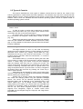
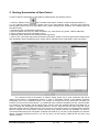
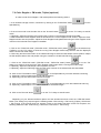
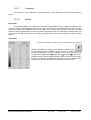
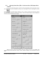
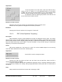
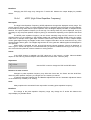
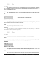
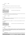
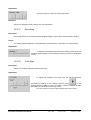
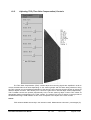
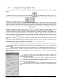
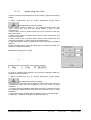
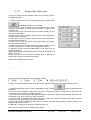
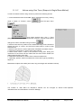
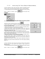
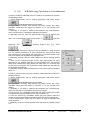
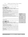
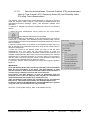
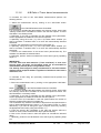
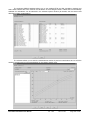
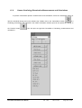
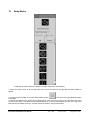
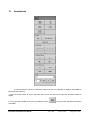
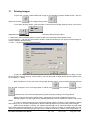
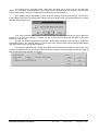
The controls on the right-side of the "Comments" tab allow you to select from the list and insert
(button "<") pre-defined texts (templates of comments) into the comments field. For creating a new template,
use the "New" button, enter the template name and then enter the template text.
After creating and saving/printing a report, close the "Report" window by clicking the "Close" button
in the "Report controls" tab. If images were added to the report images area, the software will ask if you want
to delete these images or not.
If you have finished working with the current report and saved/printed it and do not plan to add more
images to it, click the "Yes" button. If instead you plan to scan more images and add them to the same
report, then click on "No".
The list of available images and other data is cleared when selecting a new patient by clicking the
appropriate button in the "Patient" dialog. For more information read the section about starting examinations
of a new patient and the typical exam workflow.
The "Options" tab allows you to select which data must be saved/printed inside the report, how many
columns of images the report will contain and the minimum number of rows of images that will be printed on
each single page (report images view layout).
TELEMED
Echo Wave II Software User Manual
Ver. 1.8.0
2013.12.03
Page 159 of 182