1
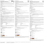
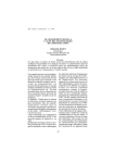
Design of future low-energy LED replacement for fluorescent tubes Master of Science Thesis in Embedded Electronic System Design CARL EWNERT Chalmers University of Technology University of Gothenburg Department of Computer Science and Engineering Göteborg, Sweden, June 2013 The Author grants to Chalmers University of Technology and University of Gothenburg the non-exclusive right to publish the Work electronically and in a non-commercial purpose make it accessible on the Internet. The Author warrants that he/she is the author to the Work, and warrants that the Work does not contain text, pictures or other material that violates copyright law. The Author shall, when transferring the rights of the Work to a third party (for example a publisher or a company), acknowledge the third party about this agreement. If the Author has signed a copyright agreement with a third party regarding the Work, the Author warrants hereby that he/she has obtained any necessary permission from this third party to let Chalmers University of Technology and University of Gothenburg store the Work electronically and make it accessible on the Internet. Design of future low-energy LED replacement for fluorescent tubes CARL EWNERT ©CARL EWNERT, June 2013 Examiner: LARS SVENSSON Chalmers University of Technology University of Gothenburg Department of Computer Science and Engineering SE-412 96 Göteborg Sweden Telephone +46(0)31-772 1000 Cover: Picture of the first working prototype Department of Computer Science and Engineering Göteborg, Sweden June 2013 Abstract This document describes the design work of an LED replacement for fluorescent tubes that is both more energy efficient and does not contain mercury. The replacement should be a retrofit which means that it can be mounted in the fixtures of ordinary fluorescent tubes without modification of the fixture. The replacement is aimed to replace the T5 and T8 types of fluorescent tubes. The document describes the theory behind the magnetic and electronic ballast and pitfalls in driving electronic devices using those ballasts. The selection process for the components used is described as well as the difficulties encountered in the designing. The methods used for making measurements are also described. The prototype made in this project have a power output of about 5 W and shows an energy conversion efficiency of over 90 %. Acknowledgements I want to thank the CEO of Tann Enterprises AB, Mika Pirttimaeki, for the great and non-exhausting support in this work. I also want to thank Jan Dahl for the technical expertise of electronics design. The examiner of this thesis, Lars Svensson, also deserves a thank you for being a calm and supporting examiner who clears out the details of examination in an excellent way. Finally, I will give huge thanks to ETA, the electronics student association of Chalmers University of Technology, for access to the electronics lab and the diversity of the components available. Without the resources that ETA provides, this thesis would not have come this far. Carl Ewnert, Göteborg June 2013 Contents 1 Introduction 1.1 Aim . . . . 1.2 Problem . . 1.3 Limitations 1.4 Method . . . . . . . . . . . . . . . . . . . . . . . . . . . . . . . . . . . . . . . . . . . . . . . . . . . . . . . . . . . . . . . . . . . . . . . . . . . . . . . . . . . . . . . . . . . . . . . . . . . . . . . . . . . . . . . . . . . . . . . . . . 2 Technical Background 2.1 Illumination requirement . . . . . . . . . . . . 2.2 Luminous flux from a single LED chip . . . . 2.3 LED packaging today and in the future . . . 2.4 Switched mode power supply for LED driving 2.5 Fluorescent tube fixture electronics . . . . . . 2.6 Tubes insertion detection . . . . . . . . . . . 2.7 High voltage ignition avoidance . . . . . . . . 2.8 Light intensity sensing . . . . . . . . . . . . . . . . . . . . . . . . . . . . . . . . . . . . . . . . . . . . . . . . . . . . . . . . . . . . . . . . . . . . . . . . . . . . . . . . . . . . . . . . . . . . . . . . . . . . . . . . . . . . . . . . . . . . . . . . . . . . . . . . . . . . . 5 . 5 . 6 . 7 . 7 . 8 . 10 . 11 . 11 3 Design 3.1 Manufacturing proposal . . . . . . . 3.2 Cooling of the LEDs . . . . . . . . . 3.3 Finding a suitable LED driver . . . . 3.4 Insertion detection . . . . . . . . . . 3.5 High voltage ignition avoidance . . . 3.6 Design of the first prototype . . . . . 3.6.1 Inductor selection . . . . . . 3.6.2 Input filter design . . . . . . 3.6.3 Current limitation . . . . . . 3.6.4 Light intensity sensing circuit 3.6.5 Remaining components . . . 3.6.6 Realization . . . . . . . . . . 3.7 Measurement method . . . . . . . . . . . . . . . . . . . . . . . . . . . . . . . . . . . . . . . . . . . . . . . . . . . . . . . . . . . . . . . . . . . . . . . . . . . . . . . . . . . . . . . . . . . . . . . . . . . . . . . . . . . . . . . . . . . . . . . . . . . . . . . . . . . . . . . . . . . . . . . . . . . . . . . . . . . . . . . . . . . . . . . . . . . . . . . . . . . . . . . . . . . . . . . . . . . . . . . . . . . . . . . . . . . . . . . . . . . . . . . . . . . . . . . . . . . . . . . . . . . . . . . . . . . . . . . . . . . . . . . . . . . 1 2 3 3 4 . . . . i . . . . . . . . . . . . . . . . . . . . . . . . . . . . . . 12 12 14 15 16 16 18 19 20 20 20 21 21 23 CONTENTS 4 Results 4.1 Illumination requirement . . . . . . . . . . . . . 4.2 Luminous flux from an LED chip . . . . . . . . 4.3 Number of LEDs needed . . . . . . . . . . . . . 4.4 Tube insertion detection . . . . . . . . . . . . . 4.5 High voltage ignition avoidance . . . . . . . . . 4.6 Light intensity circuit . . . . . . . . . . . . . . 4.7 LED driver performance . . . . . . . . . . . . . 4.8 Comparison of measured and calculated values 4.8.1 1.5 mH SMD inductor . . . . . . . . . . 4.8.2 2.2 mH THD inductor . . . . . . . . . . 4.8.3 Return of investment calculation . . . . . . . . . . . . . . . . . . . . . . . . . . . . . . . . . . . . . . . . . . . . . . . . . . . . . . . . . . . . . . . . . . . . . . . . . . . . . . . . . . . . . . . . . . . . . . . . . . . . . . . . . . . . . . . . . . . . . . . . . . . . . . . . . . . . . . . . . . . . . . . . . . . . . . . . . . . . . . . . . . . . . . . . . 26 26 26 27 27 27 27 28 28 28 28 29 5 Discussion 30 6 Conclusion 32 Bibliography 36 A Return of investment calculation 37 ii List of abbreviations BOM Bill Of Materials. CFL Compact Fluorescent Lamp. CMOS Complementary Metal-Oxide-Semiconductor. COB Chip on Board. CRI Color Rendering Index. LED Light Emitting Diode. MCPCB Metal Core Printed Circuit Board. MOS Metal Oxide Semiconductor. MOSFET Metal-Oxide-Semiconductor Field-Effect Transistor. PCB Printed Circuit Board. PEC Power Electronic Converter. ROI Return On Investment. SMD Surface Mounted Device. SMPS Switched Mode Power Supply. SO8 Small Outline 8. SPICE Simulation Program with Integrated Circuit Emphasis. THD Through Hole Device. TRIAC TRIode for Alternating Current. iii 1 Introduction nvironmental and energy saving issues have high priority in most of the world today. Both time and money is spent on making appliances more energy efficient. This is also the case for lighting where the common incandescent light bulb is deemed to consume more energy than necessary for the amount of light produced. Another common way of lighting is to use fluorescent tubes. Those are more energy efficient than the incandescent light bulb, but a new technology that arises is the use of Light Emitting Diode (LED) for lighting. LED is far more energy efficient than incandescent light bulbs and fluorescent tubes[1] which is why LED is an interesting replacement. An ordinary fluorescent tube has a luminous efficacy of about 80 lm W=1 to 100 lm W=1 [2]. It is only the recent year that has given LEDs that can excel this with a luminous efficacy of up to 170 lm W=1 [3] and in research laboratories a luminous efficacy of up to 276 lm W=1 have been achieved[4]. The LED is an interesting replacement in another aspect also; LEDs and the driving electronics do not contain mercury. Ordinary fluorescent tubes contain mercury, which is not only bad for the environment, but to the health as well. The United States Environmental Protection Agency have published instructions of measurements that must be taken when a Compact Fluorescent Lamp (CFL) breaks[5]. The measurements include evacuation of the room and leaving it with a window or door open to the outdoors for 5 min to 10 min. These instructions are made for CFL, which contains mercury, but ordinary fluorescent tubes also contain mercury and therefore the measurements mentioned above should be taken if a fluorescent tube breaks. The electric driving of LEDs is significantly different from driving fluorescent tubes and LEDs also requires cooling to not brake down. The most straightforward way to replace fluorescent tubes would be to replace the complete fixture and install a new fixture with LED that is made for driving LEDs. This is done, but it is costly and tedious so LED fixtures are mostly installed in new buildings. An alternative to LED fixtures is to make a replacement tube that uses LED and can be mounted in existing fixtures. E 1 1.1. AIM CHAPTER 1. INTRODUCTION A replacement tube that can be mounted in the same fixture as a fluorescent tube, without modification of the fixture, is called a retrofit. If modifications of the fixture is required, for example removing the ballast, it is not a retrofit. This is important because modifications of the fixture must only be made by certified electricians. If a modification of the fixture is needed, it is better to exchange the whole fixture for a LED one when the electrician is already on site because then it is not the fixture that is the main expense. The retrofits make it easy to replace the fluorescent tubes because electricians are not needed and the installation cost will not be significant because ordinary tubes need to be replaced as they wear out. There are two main types of fluorescent tubes in the market today; the older type T8 and the newer type T5, shown in fig. 1.1. The name T8 indicates it is a tube with 8/8 in (25.4 mm) diameter and T5 indicates a tube with 5/8 in (15.9 mm) diameter. The power consumed by a fluorescent tube is proportional to the length of the tube. The most common lengths of T8 tubes are 600 mm, 900 mm, 1200 mm and 1500 mm, which corresponds to powers of 18 W, 30 W, 36 W and 58 W. The most common T5 lengths are 563 mm, 863 mm, 1163 mm and 1463 mm corresponding to powers of 14 W, 21 W, 28 W and 35 W. Figure 1.1: The two main types of fluorescent tubes[6] LED retrofits for the T8 type tubes already exist on the market, but the company Tann Enterprises AB sees more potential in the technology than what is available on the market today because of the development of LEDs and its packaging[7]. They think that the retrofits can have better efficiency, longer lifetime, more similar light as the original tubes and also fit a T5 fixture[7]. As of today there exists no LED retrofit for T5 fluorescent tubes on the market as far as is known. There exists replacements but all of them require modification of the fixture and they are, therefore, not retrofits. 1.1 Aim The aim of this project is to design and make an LED retrofit for fluorescent tubes of both types T8 and T5. The retrofit will not use Surface Mounted Device (SMD) or Through 2 1.2. PROBLEM CHAPTER 1. INTRODUCTION Hole Device (THD) LEDs as most of the existing retrofits use. This design will use Chip on Board (COB) for the LEDs and a Metal Core Printed Circuit Board (MCPCB) for better heat conduction. The retrofit should be as energy and cost-effective as possible and also actively adapt the light intensity depending on factors such as amount of daylight and LED-aging. It should also not require any modifications of the fluorescent tube fixture. On every aspect such as luminous flux, Color Rendering Index (CRI) and color temperature should the retrofit be as similar to an ordinary T8 or T5 fluorescent tube as possible. The retrofit should also have a Return On Investment (ROI) of about 3 years. 1.2 Problem A fluorescent tube fixture has an ignition circuit which will ignite the fluorescent tube using a high voltage spike. To fit sensitive electronics such as LEDs and micro controllers in this fixture, special design to prevent the high voltage spike from the circuit in the fixture is required. LEDs require extensive cooling not to brake and the replacement will have to be the same size as the original fluorescent tube to be approved for selling. To make adequate cooling and at the same time fit all the components in the size of a T8 tube is tricky, but to make it fit in a T5 tube is a challenge. The whole design must be optimized for good heat dissipation and a thermal pad for electric insulation must be fitted between the board and the heat sink to prevent the heat sink to become live and causing electric shock in case of malfunction. This thermal pad will shrink the available space even more. LEDs deteriorate over time and if an old LED replacement tube is exchanged for a new one, the light difference is substantial. The deterioration of the LEDs is accelerated with heat. When a tube is inserted in a fixture, the inserted end may be powered. An ordinary tube will not conduct unless ignited, but with an electronic device, measures must be taken to prevent the other side to become live to avoid hazardous voltage exposure to the user. To make a replacement that is cost effective and energy efficient is troublesome. If a replacement is developed that is as energy efficient as possible it may consist of components that make it so expensive that it takes several years to return the investment, the investment may not be as interesting. 1.3 Limitations Tann Enterprises have already made an extensive study of the market to find the LED chip that has the highest lm W=1 or the highest light output per watt. This makes such a study in this project redundant. The power electronic converter will use a switch controller that exists on the market. The producers of those types of controllers have the same goal as in this project; to minimize losses in electronic conversion. The producers of those circuits have their own 3 1.4. METHOD CHAPTER 1. INTRODUCTION development concentrating on this task so to include a design of a new switch controller in this project would not be beneficial. The design of the cooling has already been investigated by Tann Enterprises and different solutions have been tested. This project will not include a new design of the cooling, but may include some changes to the existing design. 1.4 Method To give a deeper understanding of different factors to consider in the design, a prestudy is made before the actual design phase begins. This prestudy will help in the decision of design parameters. The design will start with a circuit that will handle the high voltage ignition in the tube fixture. A small scan of the market for LED driver circuits will be made and a driver circuit is decided upon. The design will be carried out parallel to simulations of the circuit to tune design parameters. A prototype is built to be able to test if the circuit works and if the suggested components have the correct size. Measurements on the prototype is carried out and compared with calculations to see how well the calculations describe the real behavior. 4 2 Technical Background he technical background presented in this chapter lays the foundation for the continued design. The calculations for how the illumination requirement is explained as are the ways of theoretically calculating the luminous flux from a naked LED chip. The different packaging methods are described and also a brief description of the fixture electronics is presented. The chapter finishes with a short idea of how to sense the light intensity and adapt the light output. T 2.1 Illumination requirement To give a base for the requirement of the LED retrofit the required illumination must be examined. A starting point is to look at regulations that apply for lighting in for example offices. The Health and Safety Executive of Great Britain writes that in offices, an average illuminance of 200 lx is desired[8]. For more detailed work an average illuminance of up to 500 lx is required[8]. The LED retrofit shall achieve those desired levels with the same amount of light sources as common fluorescent tubes require. This makes it possible to achieve the required illuminance levels when replacing the fluorescent tubes in the fixtures that are already installed in buildings without moving or adding fixtures. The amount of light emitted from a light source is given as luminous flux and measured in lumen. The illuminance values, given in lux (lx), is a measure of how much light is hitting a surface. The illuminance value must be converted to lumen to make it possible to calculate how much light the LED retrofit must emit, or the amount of luminous flux is needed from the LED retrofit. Lux is the same as lumen per square meter so to get the required luminous flux for a given illumination value, the lux value is multiplied by the size of the lit area. For a tube shaped light source like the fluorescent tube, the lit area is simplified to a shape seen in fig. 2.1, where l is the length of the tube. To calculate r in fig. 2.1, the height of the light source from the lit area and the beam 5 2.2. LUMINOUS FLUX FROM LED CHAPTER 2. TECHNICAL BACKGROUND Figure 2.1: Simplification of area illuminated by a tube shaped light source angle of the emitting light is needed. If the height is given as h and the beam angle as θ, then θ (2.1) r = tan · h 2 The area (A) can then be calculated with θ 2 θ A = π · h · tan + 2 · l · h · tan (2.2) 2 2 which gives the following equation for calculating the luminous flux (φv ) for a given average illuminance (Evavg ) φv = A · Evavg (2.3) 2.2 Luminous flux from a single LED chip The LEDs that should be used in this project are ordered as bare chips without any packaging. The temperature and color of the light from a white LED are dependent of the phosphor mixture in the resin used in the packaging of the LED. Details about the phosphor and resin mixture and LED fabrication is found in the article by Yukio Narukawa et. al.[9]. The data given for the naked chip is the amount of radiant flux or power at a given current. That is the total energy of the emitted light in the full spectrum, not just the visible part. The naked chip emits light in wavelengths of around 450 nm which is in the lower region of the visible spectrum of the human eye[10]. The luminous flux value for this wavelength would be low because luminous flux is the measurement of power emitted in the visible spectrum. The best way to acquire a value for the luminous flux from the chip would be to package the chip in the same way as it would be in the finished product. This is not possible in this project so an estimation must be made. The estimation can be made by selecting a chip that emits the same wavelengths as the 6 2.3. LED PACKAGING CHAPTER 2. TECHNICAL BACKGROUND one in question and acquire spectrum measurement data of this chip inside a package. This data can be applied to another naked chip with a given radiant flux and a spectrum from the chip with packaging can then be estimated. When the spectrum is estimated, the luminous flux can be calculated. 2.3 LED packaging today and in the future A view of different types of LED packaging can be seen in fig. 2.2 where they are ordered by technology era from right to left. The first one to the right is quite a big oval chip LED. This type cannot be cooled very efficiently due to the complete plastic closure of the chip (the yellow dot inside). The second type mounted on a Printed Circuit Board (PCB) is of SMD type. The SMD type has better cooling capabilities because the heat is transfered from the chip to the outside of the package where it can be transfered further away. This particular solution is using a MCPCB to decrease the thermal resistance. The next LED in fig. 2.2 (the tiny one) is also an SMD type, but with a ceramic base and better transmission of heat from the chip to the PCB with the help of extra heat transfer copper lanes. The last three are the next step in LED lighting technology. Those are a COB solution where the chip is mounted directly on an MCPCB to even further reduce the thermal resistance between the chip and the PCB. The long strip and the pillar-shaped assemblies in fig. 2.2 have the chips mounted on the MCPCB, bonded and then encapsulated with a phosphor-mixed resin. The round and flat assembly with an array of chips have milled holes which the chips are lowered into, bonded and then covered with phosphor mixed resin. The last solution uses much less phosphor-mixed resin because it is only used to fill the holes. This is a cost-saving measure because the phosphor is costly, ranging from $15 000 to $50 000 per kg depending on desired color temperature, CRI and wavelength[11]. There is about 5 % phosphor in the resin, which is not much, but when the diodes should be produced in high volume, there will be a difference. 2.4 Switched mode power supply for LED driving In a linear power supply, excessive power is transferred to heat. This means that if a linear power supply should convert 200 V to 100 V it will dissipate more heat than if it should convert 200 V to 180 V with the same current. To minimize heat dissipation, a 50 Hz transformer is used to transform the voltage down to a desired value and then a linear regulator is used to stabilize the output voltage. In this application, 325 V (rectified AC mains) will be converted down to about 42 V. This will require a 50 Hz transformer and such a transformer that can supply at least 5 W is way too large to fit inside a fluorescent tube. This makes a linear power supply unfeasible in terms of both size and energy efficiency. To get the most energy efficient power supply for the LEDs a Switched Mode Power Supply (SMPS) will be used. An SMPS is energy efficient because unlike a linear power supply, the transistors in an SMPS are either conducting or not conducting, which are 7 2.5. FIXTURE ELECTRONICS CHAPTER 2. TECHNICAL BACKGROUND Figure 2.2: Different types of LEDs ordered by technology age the modes of the transistor with least losses. For this application the output voltage will be lower than the input voltage and therefore a buck converter is the topology of choice. A schematic showing the buck converter principle can be seen in fig. 2.3. Figure 2.3: Schematic showing the principle of a buck converter The desired voltage output is generated by turning on and off the Metal-OxideSemiconductor Field-Effect Transistor (MOSFET) and then low-pass filter the output. The resulting output of a simulated SMPS is shown in fig. 2.4. 2.5 Fluorescent tube fixture electronics The T5 fixture uses an electronic ballast to ignite the fluorescent tube. This works by feeding an inductance-capacitance circuit with a high frequency pulsed voltage[12, 13], 8 2.5. FIXTURE ELECTRONICS 360V CHAPTER 2. TECHNICAL BACKGROUND V(n001) V(n002) 330V 300V 270V 240V 210V 180V 150V 120V 90V 60V 30V 0V Figure 2.4: Output from an SMPS. Unfiltered voltage in green and filtered voltage in blue. shown in fig. 2.5. When the tube is inserted the circuit is made complete and the voltage amplitude starts to increase. When the voltage amplitude has reached the required level, the tube will ignite[12, 13]. DC blocking capacitor Ballast coil 10-100 kHz Pulse Train Filament Resonance capacitor Filament Figure 2.5: Simplified schematic of an electronic ballast fixture The most common T8 fixture uses a bi-metallic thermostat to first heat the filaments 9 2.6. INSERTION DETECTION CHAPTER 2. TECHNICAL BACKGROUND in the tube and then after a certain time stop the current flow. This stopping of the current will make the coil in the ballast increase the voltage so much that it will ignite the tube which makes the current flowing through the tube instead[12, 13]. A simplified schematic of the T8 fixture is shown in fig. 2.6. The bi-metallic thermostat is only connected to the circuit when a tube is inserted. Mains AC Ballast coil Filament Starter Filament Figure 2.6: Simplified schematic of a fixture that uses a bi-metallic thermostat The T8 fixture can be found with electronic ballasts as well. 2.6 Tube insertion detection If a tube is inserted with only one end, the other end is loose and unprotected. With an ordinary fluorescent tube this is not a problem because the tube is not conducting when not ignited. When using electronics in the tube, the exposed end will be one end of the power supply input. If the inserted end is in contact with the mains phase, the other exposed end will be the neutral point and if a person touches it and makes a path to ground, current will flow through the person. Regulations that apply states that unprotected live parts should give a current of maximum 0.7 mA[14]. This current is too small to be useful for driving any LED driving power supply so an initial circuit that detects that the tube is correctly inserted in the fixture is needed. 10 2.7. IGNITION AVOIDANCE 2.7 CHAPTER 2. TECHNICAL BACKGROUND High voltage ignition avoidance To avoid the voltage increase described in section 2.5, the resonance capacitor in fig. 2.5 needs to be disconnected. To be able to disconnect the resonance capacitor, the pin out must be detected. It cannot be assumed that all fixtures are connected in the same way so a circuit that detects the connections is needed. 2.8 Light intensity sensing The LED replacement will measure the light in the tube and make adaptations so that the amount of light needed is adjusted. If the LED replacement is placed in a fixture close to a window, this feature will be used to adapt the light output to the amount of daylight. Another feature of this function is that because LEDs deteriorate over time, their light output will decrease and this will be compensated for. This light intensity measurement is achieved by using a light sensor that will measure the amount of light and give a signal to the LED driver that will adjust the current to the LEDs. 11 3 Design hen the background work is done, the implementation and prototype making can begin. This chapter begins with a description of the workflow used and pitfalls that occurred when designing the LED driver and ends with a description of the measurements made on the prototype. W 3.1 Manufacturing proposal To get the best heat transfer between the LED chip and the ambient air, the COB[15] process will be used together with an MCPCB[16]. The MCPCB will be mounted in a heat sink with an electrical insulating pad in between. The components for the driver electronics will be ordinary SMD. The manufacturing process of COB PCBs are limited to a PCB length of about 280 mm to 300 mm[17, 18]. This requires the PCB for a complete tube to be manufactured in branches. For simplicity the branches will be a length that is even dividable for all the different length of tubes. For a 563 mm tube, two branches will be used. For a 1163 mm tube, 4 branches will be used. The measurements include contacts so the useful length is 550 mm and 1150 mm respectively. This gives that a branch length of 275 mm is most suitable because it is the longest branch length that can fit a 563 mm (550 mm usable) tube. The LED replacement must have the same dimensions as an ordinary fluorescent tube in order to be approved for selling. Tann Enterprises has already designed a heat sink for both the T8 and the T5 types and the tube will consist of this heat sink with the PCB mounted in a designed slot in the heat sink[7], shown in fig. 3.1. In the slot the component size is limited to a width of 8 mm and a height of 4.7 mm. The length of the component will be along the tube which is very long relative to the other constraints. 12 3.1. MANUFACTURING PROPOSAL CHAPTER 3. DESIGN Figure 3.1: The heat sinks designed for T5 to the left and T8 to the right. The electronics together with the LEDs will go into the slot that is facing upwards in the picture. This slot will be facing downwards when the tube is mounted in a fixture. 13 3.2. COOLING OF THE LEDS 3.2 CHAPTER 3. DESIGN Cooling of the LEDs The heat sinks shown in fig. 3.1 have a measured ∆T of 14.3 K for the T8 profile and 17.6 K for the T5 profile. This cooling solution can be compared with available solutions shown in fig. 3.2, where the board has contact with the heat sink but the heat sink is hollow and has no fins so the cooling performance is not optimal. The measured ∆T of the T8 profile shown in fig. 3.2 is 24 K and 35 K for the T5 profile. Also in the T8 tube, the board is an ordinary fibreglass board with no heat conduction from the LEDs down to the heat sink. In the T5 tube, the board is an MCPCB which has much better heat conduction. The measurements of the different heat sinks were made using power resistors mounted to the heat sinks that was placed on a large piece of metal. The measurement does not show how the heat sink would perform in a fixture but it gives a comparison of the different heat sinks. 3.3 Finding a suitable LED driver To avoid reinventing the wheel, an off-the-shelf LED driver will be used in this design. The requirements of the LED driver circuit is firstly that it is housed in a package that will fit in the heat sink. This is not a problem because most LED driver circuits is housed in Small Outline 8 (SO8)-packages or smaller. Secondly the LED driver needs to be energy efficient and most of the drivers have an efficiency of over 90%. Thirdly the LED driver cannot use a transformer because the transformers available are all too large to fit in the limited space. This also makes all drivers that use a flyback configuration unusable in this design. The LED driver must also be able to be powered from mains power at 230 VAC 50 Hz. The search for a proper LED driver was conducted using the different manufacturers’ respective web site and their online tools that help in the selection of LED driver. The first problem that arose was that all LED drivers have a specification of the supply voltage, Vcc , that was very limited. The maximum voltage that one of the LED drivers could handle was only 30 V. The question that arose was: How can the tools say that this driver can be connected to mains power when it can handle only 30 V or lower? In the application notes that were published by the manufacturers a solution to this could be found in most cases. The solution was to use a zener diode in parallel with the Vcc pin, but another solution was to use a series resistance. The value of the series resistance was not given anywhere and the driver had a current consumption that varied so to calculate the value was not possible. The solution was to choose an LED driver that had an accompanying application note that described a scenario when it was powered from mains power and all the values of the needed components were given. Because the LED replacement should be able to dim its light depending on surrounding light, the LED driver needs to have some function for dimming. The problem was that most drivers that were labelled as dimmable used the old TRIAC type dimmers in the wall to dim the light, which is not what is needed here. Ordinary fluorescent tube installations are not dimmable by a TRIAC dimmer. This made the search harder 14 3.3. FINDING A SUITABLE LED DRIVER CHAPTER 3. DESIGN Figure 3.2: Available T8(left) and T5(right) tube replacements. Note that the T5 replacement shown is not a retrofit because it needs its own fixture to work. 15 3.4. INSERTION DETECTION CHAPTER 3. DESIGN because it was not possible to search by that term. Some drivers had an internal MOSFET switch and some used an external MOSFET to switch the voltage. For this application an internal switch is preferable because of the constrained space. It will also make the design a bit easier because a search and selection of a MOSFET does not have to be made. When a list of possible LED drivers began to form it would be good to make some simulations with them to evaluate their performance. This was when the next problem arose; there existed no Simulation Program with Integrated Circuit Emphasis (SPICE) models for any of the possible drivers. To make own models of a driver is doable, but the information that the manufacturers gave out about the drivers were more a manual of how to use the driver than a description of its behavior. The information was too brief to use as material for a SPICE model. This made simulations of the total circuit impossible. 3.4 Insertion detection In fig. 2.5 a simplified schematic view of a fixture with an electronic ballast and a fitted fluorescent tube is shown. The high frequency supply voltage together with the coil and the resonant capacitor will increase the voltage until the tube ignites. During the voltage increase, current flows through the filaments and heats them. To detect that a tube is properly inserted, the current through the filaments can be used. If the tube is not inserted with both ends, no current will flow through the filaments. A transformerless power supply circuit[19], seen in fig. 3.3, can be connected as a filament and the small current will be used to close a Metal Oxide Semiconductor (MOS) relay that triggers the next circuit that will avoid the high voltage ignition. D1 L Vout+ D5 R2 C1 100n D6 C2 Vout- N 470 100n Figure 3.3: Transformerless power supply circuit The transformerless power supply is not energy efficient, but it is small and does not need that many components. It will only be used during the first initial start of the LED driver and will then be disconnected. Other coices of power supply would be another switched power supply or a linear regulator. The switched power supply is too complex for this simple task and may also be too slow so that it may not have started 16 3.5. HIGH VOLTAGE IGNITION AVOIDANCE CHAPTER 3. DESIGN and avoided the high voltage spike before it strikes. The linear regulator cannot handle the voltage difference of over 300 V without a transformer which cannot be used here due to space constraints. 3.5 High voltage ignition avoidance In fig. 3.4 a circuit is shown that uses switches and two additional transformerless power supply circuits to detect which leg the current is flowing through and closes the appropriate switches and keeps the other switches open. The circuit will work independent of which end the AC and the resonant capacitor is connected to. When the power is turned on, current will flow through L1, C2, C1, R3 and the detection circuit TL1 because S5 is the only switch that is closed. This current makes TL1 close the switches S3 and S4 which powers the detection circuits TL2 and TL3. Current will flow through TL2 or TL3 depending on how the tube is connected, in this case current will flow through TL2. TL2 closes the switches S7 and S1 which makes current go through R1, which is a simulation of a load. The switch S5 is a normally closed switch, but a switch with this function could not be found in the simulation library so it is simulated as a timed switch that starts closed and opens after 2 ms which is sufficient for the circuit to enter steady state. The switches in fig. 3.4 are ideal switches that does not exist in reality. A search for a real component to use for the switches was therefore made. Solutions that used TRIode for Alternating Current (TRIAC)s were simulated but as it seems from the SPICE model of the TRIAC, such a device cannot block a supply frequency of 30 kHz which makes the TRIAC unusable for this application. It may be that the SPICE model does not cover the TRIAC workings at higher frequencies. Another component that would work is a Complementary Metal-Oxide-Semiconductor (CMOS)-relay because it uses MOS transistors that can handle higher frequencies. Here the leakage current of the relay should not exceed the requirement discussed in section 2.6. A brief search for a mechanical relay was also performed but no relays that would fit in the space constraints could be found. 3.6 Design of the first prototype When an appropriate LED driver, IC1 in fig. 3.5, was found, selection of the other components could begin. A schematic of the complete driver is shown in fig. 3.5 and the Bill Of Materials (BOM) is shown in table 3.1. To aid in this selection a tool called “Non-isolated LED Driver Design Tool”[21] was used. This tool uses the input voltage and frequency, output current, output power, dimming, Power Electronic Converter (PEC) topology, LED forward voltage drop, number of LED strings and number of LEDs per string as input parameters for the design. The input parameters used first in this design is presented in table 3.2. These values differ from the ones used later because the requirement of the luminous flux were higher 17 3.6. DESIGN OF THE FIRST PROTOTYPE CHAPTER 3. DESIGN C2 L1 8.1m 100n R7 R8 10k 10k PULSE(0 325 0 0 0 16u 33u) L Vout+ L D1 TL2 D R2 N 7k D R6 C1 3.3n D N D4 Vout+ TL3 D2 Vout- Vout- V1 D3 D R5 1k SW S6 S3 SW S2 SW S1 SW S7 SW S4 SW 1k R1 SW S5 Vout- Vout+ 1k L N R3 TL1 10k V2 .tran 2m PULSE(2 0 2m 1n 0 1) .model SW SW(Vt=1) Figure 3.4: Circuit to detect supply pins and disconnect resonant capacitor D1 D2 D3 D4 R1 L1 C1 C2 D5 L2 IC1 HV SOURCE VCC NTC DRAIN GND GND DVDT R2 Figure 3.5: Schematic of the complete LED driver 18 3.6. DESIGN OF THE FIRST PROTOTYPE CHAPTER 3. DESIGN Component name Description/Component value C2 0.1 µF for 30 kHz supply and 2.2 µF for 50 Hz supply D1-D5 Ultrafast recovery diode, 400 V, 1 A IC1 NXP LED Driver SSL21083T L1 220 µH for 30 kHz supply and 1.5 mH for 50 Hz supply L2 2.2 mH Table 3.1: Bill of materials for the LED driver design. Unlisted components use the same values as in the SSL21083 Reference Board user manual[20] Parameter Value Input voltage 230 VAC Input frequency 30 kHz Output current 60 mA Output power 5W Dimming None Topology Buck LED forward voltage drop 3.01 V Number of LED strings 1 Number of LEDs per string 27 Table 3.2: Parameters first used in the “Non-isolated LED Driver Design Tool”[21] for calculating component values (2500 lm) in the beginning which was caused by left out reflector losses in the early calculations. The “Non-isolated LED Driver Design Tool”[21] was not made for an input frequency of 30 kHz so the tool had to be run with 50 Hz instead. 3.6.1 Inductor selection The inductor, L2 in fig. 3.5, is a crucial component for the LED driver. The first run of the tool suggested an operating frequency of 60 kHz and an inductor of 5621 µH. When searching the different electronic component suppliers it soon became evident that an inductor with that inductance, the required saturation current and the physical size that would fit the available slot did not exist. One way of decreasing the required inductance is to increase the frequency but then the switching losses increases. The best possible design would have as low frequency as possible and as large inductance as possible. In eq. (3.1), which is found in the application note AN10876[22], it can be seen that by 19 3.6. DESIGN OF THE FIRST PROTOTYPE CHAPTER 3. DESIGN Parameter Value Input voltage 230 VAC Input frequency 30 kHz Output current 60 mA Output power 5W Dimming None Topology Buck LED forward voltage drop 3.01 V Number of LED strings 2 Number of LEDs per string 14 Table 3.3: Parameters used in the “Non-isolated LED Driver Design Tool”[21] after some design decisions has been made increasing the current, the inductance will decrease. Increasing the current can be made by having several LED strings with fewer LEDs in each string. On the other hand, an increased current means that the saturation current of the inductor must be larger. Inductors have either large inductance or large saturation current, not both. L= 1 2 · Iled · f ·− VO2 − (Vi · VO ) Vi (3.1) The “Non-isolated LED Driver Design Tool”[21] was rerun with different configurations of the number of LEDs per string and number of LED strings and the inductance of the inductor, the current required and the resulting switching frequency was tuned to achieve a suitable combination that also would result in an inductor that is available. An inductor, muRata 50225C, of 2.2 mH was selected which would result in a switching frequency of 56 kHz. The new input parameters are shown in table 3.3. 3.6.2 Input filter design After the rectifier, a filter needs to be in place to filter the rectified voltage, L1, C1 and C2 in fig. 3.5. For this filter another application note from NXP[23] was used as aid. The input filter is described in section 4.2.3.1 of [23] and the filter was dimensioned to be used with an input frequency of 30 kHz which meant using an inductor of 220 µH and two capacitors of 0.1 µF. 3.6.3 Current limitation To set the current supplied to the LEDs, a resistor on the SOURCE-pin of the LED driver circuit is used, R2 in fig. 3.5. This resistor is dimensioned using eq. (3.2) found in [22]. 20 3.6. DESIGN OF THE FIRST PROTOTYPE R= CHAPTER 3. DESIGN Vocp Ipeak (3.2) where Vocp is the measured voltage at the source pin when the current is at maximum. This value is specified in the data sheet for the LED driver[24] and in this case Vocp = 0.52 V. Ipeak is the peak current which for the LED driver is twice the supply current so in this case Ipeak = 240 mA. 3.6.4 Light intensity sensing circuit To be able to sense the light intensity and dim the light output, a Texas Instruments MSP430G2230ID micro controller (IC1 in fig. 3.6) was connected to the NTC pin of the LED driver, shown in fig. 3.5, to control the light output. To the micro controller, a light sensor, Taos TSL2560T (IC2 in fig. 3.6) was connected via a SMBus interface. For the auxiliary components required by the respective circuit, the components proposed in the respective circuit’s data sheet[25, 26] was used. A schematic of the light intensity sensing circuit is shown in fig. 3.6 Vdd Vdd Vdd IC2 VDD SDA ADDRSEL INT GND SCL Vdd IC1 To NTC pin DVCC P1.2/TA0.1/A2 P1.5/TA0.0/A5/SCLK P1.6/TA0.1/SDO/SCL DVSS TEST/SBWTCK RST/NMI/SBWTDIO P1.7/A7/SDI/SDA Figure 3.6: Schematic of light intensity sensing circuit The Taos TSL2560T was the cheapest sensor that had digital communication with the micro controller. The digital communication was an initial requirement to minimize complexity. When reading analog signals from a photo transistor, the complexity of noise is added. Also the idea of using only one light sensor per tube was in mind and the signal paths would be very long which would add much noise which is easier handled when the signal is digital than if it is analog. 3.6.5 Remaining components The rectifier diodes, D1 to D4 in fig. 3.5, needs some consideration because ordinary diodes used in rectifying 50 Hz cannot be used because the reverse recovery time is too long. Rectifying 30 kHz requires fast response diodes. For the remaining components that did not need any special considerations, the components listed in the SSL21083 reference board user manual[20] were used. 21 3.6. DESIGN OF THE FIRST PROTOTYPE CHAPTER 3. DESIGN The LEDs that should be used in the final design is bare chips and cannot therefore be used in this prototype because of the lack of bonding equipment and it is wise not to add unnecessary complexity in the first prototype. For this prototype ordinary SMD LEDs with about the same voltage drop as the bare chip diodes were used. 3.6.6 Realization A schematic of the LED driver was drawn in CadSoft Eagle 6.4.0 and it was made to be powered from mains power. Several of the components were not in the parts library of Eagle so they had to be created with the help of each component’s respective data sheet. When the schematic was finished and all parts had been created a single-sided circuit board was routed and created using etching technique. When the ordered components arrived, the board was assembled by hand using reflow solder technique[27]. This was especially exiting with the light sensor described in section 3.6.4 because the solder pads were placed underneath the component and the distance between the pads were only 0.25 mm so it was crucial not to use too much solder paste on those pads. After assembly, the inputs were measured so that no short-circuits were present and then the board was connected directly to mains and powered up. In this first prototype, the LED driver did not start. The first problem was thought to be the input filter which was made for 30 kHz and now this circuit was powered with 50 Hz so a change in the input filter had to be made. The prototype should be able to be powered with both 50 Hz and 30 kHz so for the second prototype a filter for 50 Hz was needed. A filter for 50 Hz requires a larger filter capacitor of 2.2 µF and a ceramic capacitor with this capacitance and at a reasonable price could not be found. The capacitor should also have a voltage rating of minimum 400 V. An electrolytic capacitor could work, but an electrolytic capacitor only has a lifetime of 5000 h[28] electrolytic capacitors found are also too big to fit the slot. To minimize the sources of errors, an electrolytic capacitor was used in the new prototype. Later discoveries showed a way of calculating the life-time of an electrolytic capacitor by using this equation published by Gregory Mirsky[29] Tm − T L=L ·2 · 10 0 Vm V 2.5 (3.3) where L0 is the number of hours the capacitor is rated for by the manufacturer at maximum temperature Tm , T is the operating temperature of the capacitor, Vm is the manufacturer-rated capacitor voltage, V is the operating voltage. By using eq. (3.3) the lifetime of a capacitor with a rated endurance of 3000 h at 105 ◦C and 400 V used at 35 ◦C and 325 V would endure 70 580 h which is about the same endurance Tann Enterprises will rate the LEDs[7]. A filter for 50 Hz was added to the schematic in Eagle and a new board was made and assembled. This new prototype did not work either. This far in the process the communication with a contact at Tann Enterprises, Jan Dahl, had increased and he gave input to changes in the design. The changes that he suggested were to shorten 22 3.6. DESIGN OF THE FIRST PROTOTYPE CHAPTER 3. DESIGN the distance between the LED driver’s Vcc pin and the capacitor that was connected to it. This is done to lower the inductance created by the copper lane. The distance to the capacitor between the Drain pin and the Dvdt pin of the LED driver circuit was also minimized. The distance to ground should also be as short as possible which meant adding a ground plane on the board and connect this plane to ground on the LED driver circuit and the input to minimize the inductance to ground. The third prototype was made with a double-sided board and close connections to ground and between LED driver circuit pins and the capacitors. The board was created, assembled and tested. It was still not working. Jan Dahl examined the design closer and took a closer look at the muRata 50225C inductor and concluded that this inductor was made to be connected to both sides of a power supply so that the line was going through one side of the inductor and the return was going through the other side as seen in fig. 3.7. This construction makes the inductor suppress differences between the two sides and work as a filter. This inductor requires to be loaded from one side and then unloaded from the other side to work and will not have a high inductance if only one side is connected as in fig. 3.8, which is the way it is connected in this design. Figure 3.7: Correct use case of the muRata 50225C common mode choke Figure 3.8: Incorrect use case of the muRata 50225C common mode choke The inductor was exchanged to another THD axial inductor with the same inductance (2.2 mH). This inductor would not fit the final design because the final design should 23 3.7. MEASUREMENT METHOD CHAPTER 3. DESIGN not have any THDs, but it is doing what it should in the troubleshooting of the circuit. When the prototype was powered up with the new inductor, the LED driver started. To get an inductor that would fit the slot, the same inductor as used in the filter, a 1.5 mH, was tested and the LED driver started with this inductor too, but the switching frequency went up from about 64 kHz to about 92 kHz. 3.7 Measurement method When making measurements on a device which is powered with mains power, certain precautions has to be made when taking measurements to avoid injury, fire and burned components. If measurements are taken with a multimeter it is vital that the probes are held firmly so that they do not slip and accidentally makes contact between line and neutral before the rectifier or between plus and minus after the rectifier. What measurement points used does not need to be considered in a safety point of view. The multimeter is limited to only measure sinusoidal AC voltages or currents and DC voltages or currents. To be able to take measurements on a switching power supply, an oscilloscope is needed. An oscilloscope differs from a multimeter in the way that it measures voltage difference. A multimeter measures the voltage difference between the two measurement leads. An oscilloscope measures the voltage difference between ground and the measurement point. The probe of an oscilloscope has a ground lead that connects the circuit to ground, and a measurement point to measure the voltage. Because the ground lead connects the circuit to ground, an unisolated circuit that is connected to mains power cannot be connected to the ground lead because it will create a short to ground. To overcome this, two probes were used connected to the two channels on the oscilloscope. One probe were connected to the minus pole and the other one were connected to a measuring point. The ground leads were not connected to the circuit at all. This makes the oscilloscope measure the difference between its ground, which is the same as the circuit’s because they are connected to the same outlet, and the measuring point. The MATH function in the oscilloscope was then used and the values from the probe connected to minus were subtracted from the values of the probe connected to a measurement point. This is a cheap way of creating a differential probe. It is not very accurate which was pointed out by Jan Dahl. Jan said that an isolation transformer was needed between the circuit and mains power to be able to take accurate measurements. An isolation transformer were acquired which makes it possible to connect the ground lead of the oscilloscope probe to any point in the circuit because the circuit is now galvanically isolated from mains power[30]. Precautions must still be taken not to short minus and plus or line and neutral with the probe. A drawback with an oscilloscope is that it only measures voltage. To measure current, a certain current probe that converts current to voltage is needed. A current probe was not available so a different method to measure current was needed. The current was measured by inserting a resistor with a low resistance in the circuit and measure the voltage drop over it. The current through the resistor can then be calculated by using 24 3.7. MEASUREMENT METHOD CHAPTER 3. DESIGN Ohm’s law u (3.4) R where R is measured with 4 wire measurement using a Fluke 8808A multimeter. To calculate the energy efficiency of the circuit the input voltage and current as well as the output voltage and current must be measured. The measurements are then read into a computer that calculates the average power, Pavg , from the sampled data using u=R·i⇒i= Pavg T2 X 1 v(t) · i(t) · (t2 − t1 ) = T2 − T1 (3.5) T1 Where T1 is the start time and T2 is the end time, v(t) is the voltage and t2 − t1 is the duration of one sample. The current i(t) is not given directly so by combining eqs. (3.4) and (3.5) the equation Pavg = T2 X 1 vres (t) · (t2 − t1 ) v(t) T2 − T1 R (3.6) T1 is acquired where vres (t) is the voltage over the series resistor used and R is the resistance of the same resistor. The energy conversion efficiency, η, is then calculated using η= Pout Pin (3.7) The measurement methods above were used on the 1.5 mH inductor and a result was obtained. The inductor was then exchanged to the 2.2 mH inductor to measure the difference between the two inductors. When the circuit was powered up, the resistor R1, seen in fig. 3.5, popped and all LED chip burned. It was evident that a high current had gone through the circuit. A small solder pearl had dropped on to the board between the output of the driver circuit (IC1) and ground. The pearl was removed and the resistor, R1, the LEDs and driver circuit, IC1, was exchanged for new ones and a new measurement was made. This time the result showed an input power of 13 W which is impossible because the circuit worked and nothing was shorted. The inductor was changed back to the 1.5 mH one and after tedious troubleshooting, it was discovered that the resistor used for measuring the current had changed its resistance, possibly because of the high current earlier. The resistor used for current measurement on both the input and load was exchanged and a new measurement was made which now gave good readings again. The inductor was exchanged again for the 2.2 mH one and measurements of this inductor could be made. It was discovered that the order of the measurements was taken had an impact. If the input power was measured before the output power, the energy conversion efficiency was lower than if the output power was measured before the input power. When the results for the first measurement described in section 4.7 was acquired, the input power 25 3.7. MEASUREMENT METHOD CHAPTER 3. DESIGN was measured before the output power and for the results of the second measurements, the output power was measured before the input power. This was because when the LEDs heated up, the forward voltage decreased and the LEDs consumed less power as the time went because of bad cooling. 26 4 Results he final results from calculations and measurements are presented in the beginning of this chapter. The chapter continues with comparisons between the calculations and the measured data. The chapter ends with a ROI calculation to get a grip of how high the price tag of the final LED replacement can be so that it will have paid back itself with the energy savings it makes. T 4.1 Illumination requirement The illumination requirement is calculated using a light source with a beam angle of 120° (common value for LEDs) and a length of 1200 mm, 1.4 m above a table (2.2 m above the floor and a table with a height of 0.8 m). By using eq. (2.2) an illuminated area of 24.3 m2 is retrieved. This area is then used in eq. (2.3) together with the required illuminance value of 200 lx in office areas, from the HSE document[8], to acquire a required luminous flux of 4858 lm. A standard T8 fluorescent tube with a length of 1200 mm gives 2850 lm[2] which gives the reason for having two fluorescent tubes in one fixture, the area is increased with two tubes but not so much that it will make a significant difference. The luminous flux from a fluorescent tube is emitted in 360° and about 30 % to 40 %[31, 32] of it is lost in the reflector. This means that a luminous flux of about 2000 lm for a tube of length 1200 mm is sufficient for an LED replacement for common office lighting. 4.2 Luminous flux from an LED chip A contact at Tann Enterprises, Li Kang[33], has made the calculations of the luminous flux from the chips that shall be used and the luminous efficacy (lm W=1 ) of them. The results were presented as a table with the supply current used as input and the luminous efficacy and power consumption as a result. This table was used when tuning the design 27 4.3. NUMBER OF LEDS NEEDED CHAPTER 4. RESULTS parameters supply current and the number of LEDs required to get the required luminous flux. 4.3 Number of LEDs needed The prototypes made was made with a supply current of 60 mA and 28 LEDs. With a supply current of 60 mA the LEDs have a luminous efficacy of 130 lm W=1 which gives this set up a luminous flux of 2500 lm, for a 1200 mm tube, which was the requirement initially. This requirement was then revised to 2000 lm when the losses in the fixture were taken into account. When the first three prototypes were made and it was discovered that a different inductor was needed, the supply current and the number of LEDs needed were revised to get a lower current to be able to use a larger inductor. The setup that is the most promising at the time of writing is a supply current of 35 mA and a requirement of 136 LEDs for a tube length of 1200 mm. The luminous efficacy of the LEDs when supplied with 35 mA is 155 lm W=1 . These numbers are still worked with to get the most optimal solution. 4.4 Tube insertion detection The tube insertion solution proposed in section 2.6 has only been simulated. The simulations show that it would work as intended but the simulations also contain a simplified model of the electronic ballast so a prototype would be needed to test if the circuit would work with a real electronic ballast. Such a prototype has not been made. Later simulations also showed that R2 in fig. 3.3 will dissipate a lot of power, in the range of about 50 W. This is not feasible for such a circuit so it will need a redesign. 4.5 High voltage ignition avoidance The disconnect circuit shown in fig. 3.4 and described in section 3.5 has only been simulated in LTSpice. The simulations show that the circuit would work as intended, but the switches are ideal and the model of the ballast is simple so a prototype is needed to try the circuit with a real electronic ballast. Such a prototype has not been made. 4.6 Light intensity circuit The light intensity circuit described in section 3.6.4 was implemented on the prototype board and assembled but it was never used. 28 4.7. LED DRIVER PERFORMANCE 4.7 CHAPTER 4. RESULTS LED driver performance Using the power measurement methods described in section 3.7, the energy conversion efficiency can be calculated. For the prototype with 2 strings of 14 LEDs each and the 1.5 mH inductor, two measurements were made at different time instances. The first measurement showed a conversion energy efficiency of 87 % and the second measurement showed a conversion efficiency of 93 %. For the same prototype but with an inductor of 2.2 mH the measured conversion efficiency was 91 % in the first measurement and 96 % in the second measurement. 4.8 Comparison of measured and calculated values The performance of the prototype is different depending on the inductor used so the comparisons will be made for each kind of inductor. The current supplied by the driver is decided by the source resistors as described in 3.6.3. The resistors used are the same as in the reference design user manual[20], 4.7 W in parallel with 4.3 W, which sets the peak current to 231.6 mA and the supply current is then only 57.9 mA per LED string instead of the described 60 mA. The measured current is even lower, 54 mA, due to resistance tolerances in the resistors. This current is the one used in the following calculated values. The conversion energy efficiency calculations in the “Non-isolated LED Driver Design Tool”[21] are dependent of which ferrite material is used in the inductor core. In the data sheets of the inductors[34, 35], the ferrite material is not given so the core with least losses have been selected in the “Non-isolated LED Driver Design Tool”[21]. This can be one of the reasons that the energy conversion efficiency calculations does not coincide with the measured values. 4.8.1 1.5 mH SMD inductor When the values in table 4.1 are entered in the “Non-isolated LED Driver Design Tool”[21] the calculated switching frequency is 87 kHz. The measured switching frequency is 92 kHz. This difference can be explained by looking in the data sheet of the BOURNS SDR0805 inductor[34] and discover that the tolerance of the inductance is ±10 % and the inductance can then be as low as 1.35 mH which will give a calculated switching frequency of 95 kHz. The calculated energy conversion efficiency, using 1.35 mH inductor, is 89 % and as seen in section 4.7 the measured performance is about the same. 4.8.2 2.2 mH THD inductor The same values as in table 4.1 is used but the inductance is set to 2.2 mH instead. The calculated switching frequency is then 61 kHz and the measured switching frequency is 57.45 kHz. The data sheet for the inductor[35] shows a tolerance of ±10 % which can give calculated switching frequencies down to 56 kHz. The calculated energy conversion efficiency is 90.6 % which is a bit lower than the measured value. 29 4.8. COMPARISON OF VALUES CHAPTER 4. RESULTS Parameter Value Input voltage 230 VAC Input frequency 50 Hz Output current 54 mA Output power 5W Dimming None Topology Buck LED forward voltage drop 3.01 V Number of LED strings 2 Number of LEDs per string 14 Inductance 1.5 mH Table 4.1: Parameters used in the “Non-isolated LED Driver Design Tool”[21] to get the calculated switching frequency and energy conversion efficiency used for comparison 4.8.3 Return of investment calculation A summation of the component cost for the components used shows a complete cost of about 160 SEK for a 1200 mm T8 retrofit. The prices that were used to calculate this cost was retreived from Farnell’s website[36] and the price for 1000+ components were selected for each component. The number of components needed was estimated based on ideas and the price for the detection circuit (section 3.4) and ignition avoidance circuit (section 3.5) is not included as these circuits are not finished. To have an ROI of 3 years, the final price of the tube must be about 690 SEK based on a usage of 12 h/d and 21 working days per month and a price of 1 SEK/kW h. The complete ROI is presented in appendix A. 30 5 Discussion o get a working LED retrofit requires much work and there is more details that must be concerned than meets the eye at first. The problem of the tube insertion detection is not an easy knot to untie and it is only solved in theory in this thesis, a prototype is needed and more testing before it can be concluded that the proposed solution will work. As mentioned in the results, section 4.4, the transformer less circuits needs a redesign because of the high power dissipation in the series resistor. To avoid the high voltage ignition is also a problem that is only solved in theory and a prototype would be needed to verify the solution in reality. The proposed circuit in section 3.5 needs real switches or relays. It was proposed to use CMOS-relays in this circuit but the search for such relays showed that these components have a price tag that is too high so a better testing of the circuit with TRIACs, that are much cheaper, is needed. The number of LEDs used in this solution can be changed easily because the LED driver will adapt the voltage so that the current set by the source resistors is achieved. The supply current is also altered quite easily by exchanging those sense resistors. Discussions with Tann Enterprises about what supply current should be used and how many LED chips should be used indicates that this is not fixed and may be changed in future work. This is because a lower supply current will increase the life time of the LED chips and increase the efficacy of them (lm W=1 ) but it will also require a larger number of chips to get the same luminous flux. Measurements of the driver performance showed that the energy conversion efficiency is very high, more than 90 %. This value is largely dependent of the exactness in the measurement of the resistors used for current measurement and it is not as accurate as may be desired. The measurement was made with a 4-wire measurement on a Fluke 8808A and the measurement supplies the resistor with a DC current when performing the measurement. The resistor is however used in quite high frequencies and the resistors T 31 CHAPTER 5. DISCUSSION used are not only resistive as they are of carbon film type so the impedance of the resistor is different when the resistor is used in the circuit. Regardless of the absolute value, the same measurement method was used for both inductors and it can be concluded that a larger inductor results in a better energy conversion efficiency due to the lowered switching frequency. The sensing of the light intensity were not tried out because of time constraints. The light sensor was also quite expensive so this feature may be an extra feature if the price of the solution cannot be lowered. One way of lowering the price would be to use a photo resistor and let the micro controller do the measuring instead. The cost of the retrofit is not very accurate at this moment because the prices of the components used were taken from just one retailer and the detection and ignition avoidance circuits are missing in the calculations because they are not finished and tested. Also the proposed ignition avoidance circuit in section 3.5 with CMOS relays is very expensive because the CMOS relays cost about 35 SEK a piece and 6 of them is needed in the purposed circuit. This would mean that 210 SEK would be the cost for the CMOS relays themselves which is not feasible. For the tube to fill the aim of a ROI of 3 years it has to have a price tag of about 690 SEK which is quite high and gives margin so that good quality components can be used. 32 6 Conclusion his project has shown that the finished LED retrofit can have an energy conversion efficiency of over 90 % and that the components needed can fit the limited space available. Although a complete LED retrofit were not made, the project is a leap towards a finished retrofit. The luminous flux is the same as for an ordinary fluorescent tube but the CRI and color temperature is dependent of the phosphor-resin mixture which is not discussed in this project. The COB and MCPCB solution has not been tried out in connection with this project but previous work has shown that it is possible to use this technology for LEDs. The electronics should theoretically be able to use both the T5 and T8 fixture for power supply but it has not been tested. The prototype made in this project cannot be connected directly to an unmodified fixture because the special circuitry discussed in sections 3.4 and 3.5 has not been implemented or tested. The circuitry for the active adaptation of light intensity depending on surrounding light has been implemented but no programming has been made and no testing of the light sensor has been carried out. The cost of the design can be cut by searching for cheaper retailers. Also the calculation is made on 1000+ components of each which is a bit low compared to the number of tubes there exists that can be replaced. To cut some of the costs, some components can be reused to replace others. For example there are two different capacitors in the design with the same capacitance, 0.1 µF but one of them is rated for 400 V and the other one is rated for 5 V. If the 400 V rated capacitor is used instead of the 5 V rated, then the order volume of the 400 V capacitor will go up and the 5 V capacitor is not needed. When the order volumes increase, it can be worth the extra cost for the 400 V rated capacitor so that the 5 V rated capacitor does not need to be ordered. To make a finished LED retrofit for T5 and T8 tubes this is a proposed way of continuation: T The prototype needs to be tested in an actual fluorescent tube fixture for both the 33 CHAPTER 6. CONCLUSION T5 and the T8 type to verify that the circuit is working with that kind of supply. The special circuits that detect whether the tube is inserted properly in the fixture and that disconnects the fixture components that ignites the tube normally, needs to be tested and maybe redesigned. The light sensing circuitry needs to be tested A prototype MCPCB that has the same shape and size as the final one that fits the slot in the heat sink should be made. This prototype may also use the final LED chips together with the resin-phosphor mixture. Before the product can begin production, a number of certifications and classifications must be made to make it approved for selling. 34 Bibliography [1] S. Bloom, “Bright light of the future: Leds take new focus,” Journal of Property Management, vol. 77, no. 6, pp. 28–33, November 2012. [2] GE Consumer & Industrial Lighting. Polylux xlr. Accessed: 15 February 2013. [Online]. Available: http://www.gelighting.com/eu/lighting applications/ downloads/PolyluxXLR.pdf [3] J. Lin, “Key trends in the development of led lighting technology,” April 2012, accessed: 9 May 2013. [Online]. Available: http://www.digitimes.com/Reports/ Report.asp?datepublish=2012/04/03&pages=RS&seq=400 [4] LED Professional. (2013, February) Cree sets new r&d performance record with 276 lumen-per-watt power led. Light Generation, White Paper, Accessed: 9 May 2013. [Online]. Available: http://www.led-professional.com/technology/light-generation/ cree-sets-new-r-d-performance-record-with-276-lumen-per-watt-power-led [5] United States Environmental Protection Agency. (2013, January) Cleaning up a broken cfl: Detailed instructions. Accessed: 23 May 2013. [Online]. Available: http://www2.epa.gov/cfl/cleaning-broken-cfl-detailed-instructions [6] C. Taube. (2005, April) Leuchtstofflampen. Accessed: 23 May 2013. [Online]. Available: https://en.wikipedia.org/wiki/File:Leuchtstofflampen-chtaube050409. jpg [7] M. Pirtimaeki, “Ceo,” Private communication, Tann Enterprises AB, 2013. [8] Health and Safety Executive, Lighting at Work, 2nd ed. HSE Books, 1997. [9] Y. Narukawa, M. Ichikawa, D. Sanga, M. Sano, and T. Mukai, “White light emitting diodes with super-high luminous efficacy,” Journal of Physics D: Applied Physics, vol. 43, no. 35, p. 354002, 2010. [Online]. Available: http://stacks.iop.org/0022-3727/43/i=35/a=354002 [10] G. Stark, “Light,” Encyclopedia Britannica Online Academic Edition, Feb 2013. 35 BIBLIOGRAPHY BIBLIOGRAPHY [11] Intematix Corporation, “Phosphor quotation,” 2012, private communication. [12] Wikipedia. (2013) Fluorescent lamp. Accessed: 21 February 2013. [Online]. Available: http://en.wikipedia.org/w/index.php?title=Fluorescent lamp&oldid= 539357269 [13] F. D. IV. (2013) The fluorescent lighting system. Accessed: 21 February 2013. [Online]. Available: http://nemesis.lonestar.org/reference/electricity/fluorescent/ index.html [14] IEC, IEC 60598-1 ed7.0: Luminaires - Part 1: General requirements and tests. International Electrotechnical Commission, 2008. [15] “Packaging options—chip on board,” in Integrated Circuit Packaging, Assembly and Interconnections. Springer US, 2007, pp. 93–101. [Online]. Available: http://dx.doi.org/10.1007/0-387-33913-2 7 [16] M. Yoo, H. Cho, S. Kim, H. Lim, S. Park, W. Lee, J. Kim, T. Seong, B. Jeong, and S. Nahm, “Electric field assembled anisotropic dielectric layer for metal core printed circuit boards,” Electron Device Letters, IEEE, vol. 33, no. 11, pp. 1607–1609, nov. 2012. [17] J. Mo, “Technical Manager, Shenzhen Shennan Microelectronics CO. LTD,” january 2013, private communication. [18] R. Lee, “Technical Manager, Shenzhen AAA Optoelectronics CO. LTD,” january 2013, private communication. [19] R. Condit, “Transformerless power supplies: Resistive and capacitive,” no. AN954, 2004. [20] “Ssl21083 reference board user manual,” User manual, NXP Semiconductors, November 2011. [21] NXP Semiconductor. (2013) Non-isolated led driver design tool. Accessed: 21 May 2013. [Online]. Available: http://www.nxp.com/design-portal/non-isolatedled-driver-design-tool.html [22] “Buck converter for ssl applications,” Application note, NXP Semiconductors, June 2011. [23] “Non-dimmable buck converter in low ripple configuration,” Application note, NXP Semiconductors, October 2012. [24] “Greenchip drivers for led lighting,” Data sheet, NXP Semiconductors, December 2011. [25] “Ms430g22x0 mixed signal controller,” Data sheet, Texas Instruments, July 2012. 36 BIBLIOGRAPHY [26] “Tsl2560, tsl2561 light-to-digital converter,” Data sheet, Taos, December 2005. [27] Wikipedia. (2013) Reflow soldering. Accessed: 13 May 2013. [Online]. Available: http://en.wikipedia.org/wiki/Reflow soldering [28] “Aluminum electrolytic capacitors/ eb(large can size),” Data sheet, Panasonic, November 2012. [29] G. Mirsky. (2008, August) Determining end-of-life, esr, and lifetime calculations for electrolytic capacitors at higher temperatures. Accessed: 17 May 2013. [Online]. Available: http://www.edn.com/design/components-andpackaging/4326347/Determining-end-of-life-ESR-and-lifetime-calculations-forelectrolytic-capacitors-at-higher-temperatures [30] Wikipedia. (2013) Galvanic isolation. Accessed: 14 May 2013. [Online]. Available: http://en.wikipedia.org/wiki/Galvanic isolation [31] Philips. (2013, May) Tbs417 - 1 pc - 35 w - hf performer - semi-high-gloss optic 3d micro-lamellae. Accessed: 8 May 2013. [Online]. Available: http://download.p4c. philips.com/l4b/9/910501913703 eu/910501913703 eu pss aen.pdf [32] ——. (2013, May) Tbs417 - 1 pc - 35 w - hf performer - micro-lens optic in polycarbonate cover. Accessed: 8 May 2013. [Online]. Available: http://download. p4c.philips.com/l4b/9/910501902903 eu/910501902903 eu pss aen.pdf [33] L. Kang, “Phosfor conversion factor,” 2012, private communication. [34] “Sdr0805 series - smd power inductors,” Data sheet, BOURNS, May 2012. [35] “Model hm50 & hm51 miniature power inductors,” Data sheet, Bi Technologies, March 2003. [36] Premier Farnell plc. (2013, May) Farnell sverige. Accessed: 23 May 2013. [Online]. Available: http://se.farnell.com/ 37 A Return of investment calculation 38 ROI ANALYSIS - TANNENTERPRISES.COM Product ID:G13SMD1502000LE235000120801200FGNT8/1 (Tube) LED ROI Payback period in months 36 Total savings monthly with this LED-light SEK 8,00 Total savings annually with this LED-light 95,98 Total life span savings with this LED light (Based on estimated life span of 100000 hours) 2 466,15 Fluorescent light cost over estimated LED lifespan 100000 hours 400,00 Cost per choosen single LED light 687,85 Cost of Installation per single LED light 20,00 Total cost to retrofit with LED 707,85 Financial benefits Current lighting Savings with LED lighting LED lighting Saving in % Power per single light source (W) 52.44 20.7 31.74 60.53 Number of LED lamps in this calculation 1 1 0 0 Kilo-watt-hours per day single light source (kWh) 0.63 0.25 0.38 60.53 Daily operating Hours (hrs) 12 12 0 0 Working days per month 21 21 0 0 Total kWh per month (kWh) 13.21 5.22 8 60.53 kWh cost 1 1 0 0 Monthly kWh cost 13.21 5.22 8 60.53 Maintenance & ballast monthly cost single light source 8.74 3.45 5.29 60.53 System maintenance & ballast monthly cost 8.74 3.45 5.29 60.53 HVAC load cost factor (%) 15 15 0 0 System HVAC monthly use in Watts 2.38 0.94 1.44 60.53 Total cost per month with Ballast losses, Maintenance and HVAC costs 13.21 5.22 8 60.53 Total annual cost to operate 62.6 95.98 60.53 158.58 Environmental benefits Current lighting LED lighting Savings Annual system electricity usage incl. ballast and HVAC costs (kWh) 158.58 62.6 95.98 Energy / Power cost 158.58 62.6 95.98 System, life span energy, consumption (kWh) 5244 2070 3174 CO2-emissions annually (metric tonnes)* 0.13 0.05 0.08 CO2-emissions over estimated life span (metric tonnes)* 4.36 1.72 2.64 Total mercury deductions/savings (mg) 2.5 0 2.5 Car removal equivalent (cars)** 2.07 0.59 1.48 Tree planting equivalent (acres of trees)*** 1.68 0.66 1.02 *Calculation based on USEPA eGRID2007 Version 1.1 estimated national avg of 0.6033Kg CO2/kWh = 1.33 lbs CO2/kWh **Calculation based on USEPA Emission Facts, 2000 ***Calculation based on Urban Forestry Administration estimate of 2.6 tons of CO2 stored per acre of trees per year © tannenterprises.com