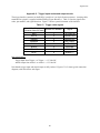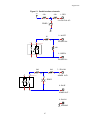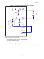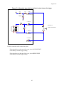
1
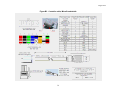
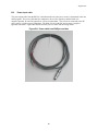
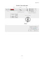
August 2012
HARDWARE USER’S MANUAL
RibEye™ Multi-Point Deflection Measurement System
for the Hybrid III ATD – 50th Male 2-Axis RibEye
Boxboro Systems LLC
978-257-2219
www.boxborosystems.com
© 2012 Boxboro Systems LLC
1
August 2012
Table of Contents
1.0
Page
Overview.............................................................................................................................5
2.0
Mounting the RibEye .......................................................................................................10
2.1 Controller mounting.................................................................................................12
2.2 Installation and removal of the controller connector and cable ...............................12
2.3 Sensor head mounting ..............................................................................................18
2.4 LED mounting..........................................................................................................18
Angled vs. flat LEDs ..........................................................................................18
LED mounting procedure ...................................................................................19
2.5 LED connector block mounting ...............................................................................26
2.6 Interface/trunk box mounting...................................................................................26
3.0
Operating the RibEye.......................................................................................................28
3.1 Status light and manual arming................................................................................28
3.2 RibEye IP address ....................................................................................................28
3.3 LED flashing on power up .......................................................................................28
4.0
RibEye Software ...............................................................................................................29
5.0
RibEye Maintenance ........................................................................................................30
Appendixes
A
RibEye specifications..........................................................................................................31
A.1 Accuracy and measurement range.............................................................................31
A.2 Power requirements...................................................................................................36
A.3 Data acquisition and storage......................................................................................36
B
Cable assemblies .................................................................................................................37
B.1 Controller cable .........................................................................................................37
B.2 Power input cable ......................................................................................................40
B.3 Trigger cable..............................................................................................................42
B.4 LED cables ................................................................................................................43
C
Trigger inputs and armed output circuits ............................................................................46
2
August 2012
List of Figures and Tables
Figure No.
Page
1
RibEye components............................................................................................................... 6
2
Front view of spine................................................................................................................ 7
3
Rear view of spine................................................................................................................. 8
4
Interface/trunk box ................................................................................................................ 9
5
Interface/trunk box with cables ............................................................................................. 9
6
Diagram for mounting RibEye components......................................................................... 11
7
RibEye controller connector and cable ................................................................................ 12
8
Install or remove screws that clamp the connector to the controller .................................... 13
9
Pull the connector out with the lanyard after removing screws ........................................... 14
10
Pop the connector from its mate inside the controller using a screwdriver
to lever the connector upward .............................................................................................. 15
11
Connector popped out of the controller and ready to be removed ....................................... 16
12
Controller in back of spine after connector and cable have been removed .......................... 17
13
LED radiation pattern........................................................................................................... 18
14
Rib with double-stick foam tape in place ............................................................................. 19
15
LED and angled mounting block.......................................................................................... 20
16
LED snapped into angled mounting block ........................................................................... 20
17
Flat LED in place on rib with lead wire secured by nylon tie.............................................. 21
18
Angled LED in place on rib with lead wire secured by nylon tie ........................................ 21
19
Heat-shrink sleeve in place over flat LED ........................................................................... 22
20
Heat-shrink sleeve in place over angled LED ...................................................................... 22
21
Applying heat to shrink the sleeve and secure the LED tightly to the rib............................ 23
22
Flat LED in place after heat-shrinking ................................................................................. 24
23
Angled LED in place after heat-shrinking ........................................................................... 24
24
Flat LED and lead wire installed.......................................................................................... 25
25
Angled LED and lead wire installed .................................................................................... 25
26
LED connector blocks on RibEye sensor heads, rear view of spine .................................... 26
27
Interface/trunk box ............................................................................................................... 27
A1
RibEye measurement range and typical accuracy, Rib 1 X axis .......................................... 32
A2
RibEye measurement range and typical accuracy, Rib 1 Y axis .......................................... 33
B1
RibEye controller cable and connector ................................................................................ 37
B2
Controller cable, Souriau connector end details................................................................... 38
B3
Controller cable, Microfit end details................................................................................... 39
B4
Power cable from RibEye trunk box .................................................................................... 40
B5
Power cable details............................................................................................................... 41
B6
Trigger cable from RibEye trunk box .................................................................................. 42
B7
Trigger cable details ............................................................................................................. 43
B8
LED cables (lead wires) attached to connector blocks in RibEye sensor heads
(rear spine view)................................................................................................................... 44
3
August 2012
List of Figures and Tables, continued
Figure No.
Page
B9
LED cables, connector blocks, and sensor heads (front spine view) ................................... 44
B10 LED cable soldered to LED assembly ................................................................................. 45
B11 LED cable, Microfit end details ........................................................................................... 45
C1
Partial interface schematic ................................................................................................... 47
C2
Tape switch or isolated contact closure for trigger .............................................................. 48
C3
Alternative tape switch or isolated contact closure for trigger............................................. 49
C4
Active trigger source ............................................................................................................ 50
C5
Differential trigger source .................................................................................................... 50
C6
Armed output connection ..................................................................................................... 51
Table No.
A1
Maximum error specifications over the range of Z offsets .................................................. 31
A2
RibEye accuracy data (zero Z offset) ................................................................................... 34
A3
RibEye accuracy data (Z offset of –10 mm) ........................................................................ 34
A4
RibEye accuracy data (Z offset of +10 mm) ........................................................................ 34
A5
RibEye accuracy data (Z offset of –20 mm) ........................................................................ 35
A6
RibEye accuracy data (Z offset of +20 mm) ........................................................................ 35
A7
RibEye power requirements ................................................................................................. 36
C1
Trigger cable signals ............................................................................................................ 46
4
August 2012
HARDWARE USER’S MANUAL
RibEye™ Multi-Point Deflection Measurement System
for the Hybrid III ATD – 50th Male 2-Axis RibEye
1.0
Overview
The RibEye measurement system as designed for this ATD (anthropomorphic test dummy) has the
following components, shown in Figure 1:
• Two sets of six LEDs (total of 12) that are mounted on the ribs
• Two optical sensor heads that derive the position of the LEDs during RibEye operation
• Two LED connector blocks that are built into the sensor heads
• The RibEye controller, which is mounted inside the back of the spine
• The interface box, also called the trunk box because it is usually placed in the trunk of the
vehicle.
Appendix A provides detailed specifications for the RibEye, including accuracy, measurement range, and
power requirements.
5
August 2012
Figure 1. RibEye components
A = LEDs; B = sensor heads; C = LED connector blocks; D = controller; E = spine; F = interface/trunk box
D
E
C
F
C
B
B
A
6
A
August 2012
Figures 2 and 3 show the sensor heads, LED connector blocks, and controller location in greater detail.
The interface/trunk box has sockets for the RibEye controller, power input, and trigger cables
(Figures 4 and 5). Appendix B contains more information on cable assemblies.
Figure 2. Front view of spine
A = sensor heads; B = LED connector blocks
B
B
A
A
B
B
7
August 2012
Figure 3. Rear view of spine
A = controller; B = controller mounting screws;
C = RibEye controller connector and cable to trunk box;
D = controller connector screws; E = LED connector blocks
B
B
A
D
B
D
C
B
E
E
E
E
8
August 2012
Figure 4. Interface/trunk box
Figure 5. Interface/trunk box with cables
A = RibEye controller; B = power; C = trigger
A
C
B
9
August 2012
2.0
Mounting the RibEye
A diagram for mounting the RibEye controller and sensor heads is shown in Figure 6. The controller and
sensor heads should be mounted to the dummy’s spine before assembling the ribs onto the spine. The
following mounting instructions are specific to the 50th Male 2-axis RibEye for the Hybrid III ATD.
10
August 2012
Figure 6. Diagram for mounting RibEye components
1 = controller; 2 = left sensor head; 3 = right sensor head; 4 = four screws for mounting controller (socket head cap #10-32 x 5/8);
5 = six screws for mounting sensor heads (button head cap #10-32 x 5/16)
11
August 2012
2.1
Controller mounting
The controller slides into the back of the spine and is attached with four screws (see Figure 3-B and
Figure 6).
2.2
Installation and removal of the controller connector and cable
The RibEye controller connector (Figure 7) plugs into the back of the controller and is kept in place by
two #4-40 x 5/8 button-head cap screws (Figure 3-D). The communications cable runs out of the
controller and then down under the dummy skin (jacket) to exit at the bottom of the dummy skin. The
cable is routed to the interface/trunk box.
Figure 7. RibEye controller connector and cable
To install the controller cable, insert the connector into the controller and use an Allen wrench to tighten
the two #4-40 screws, as shown in Figure 8.
To remove the connector and cable after a test, first remove the screws, then pull on the pink lanyard, as
shown in Figure 9. This will pop the connector out from its mating connection inside the controller.
Alternatively, you can use a flat-head screwdriver to pop the connector out. Insert the screwdriver into
the slots on the bottom of the connector as shown in Figure 10. Then twist the screwdriver to lever the
connector out (Figure 11).
After the connector has been popped out, it can be pulled out of the controller safely. DO NOT PULL
ON THE CABLE ITSELF. Figure 12 shows the back of the spine with the controller connector and
cable removed.
12
August 2012
Figure 8. Install or remove screws that clamp the connector to the controller
13
August 2012
Figure 9. Pull the connector out with the lanyard after removing screws
14
August 2012
Figure 10. Pop the connector from its mate inside the controller
using a screwdriver to lever the connector upward
15
August 2012
Figure 11. Connector popped out of the controller and ready to be removed
16
August 2012
Figure 12. Controller in back of spine after connector and cable have been removed
17
August 2012
2.3
Sensor head mounting
The two optical sensor heads are mounted to the left and right sides of the spine. Each sensor head is
attached to the spine with three screws, as shown in Figure 6. Note that the spine has alignment pins that
fit into precision holes in the sensor heads. The sensor heads also contain built-in connector blocks for
the LED cables to plug into. Section 2.5 and Appendix B.4 provide more details on the LED connector
blocks and cables.
2.4
LED mounting
The LEDs should be mounted to the ribs before the ribs are assembled onto the spine. The top rib is
Rib 1, and the bottom rib is Rib 6. Left and right refer to the dummy’s left and right sides. The LED
cables and connector blocks are marked 1–6 for Ribs 1–6. DANGER: The LEDs are very bright when
driven at full power. Never look directly at the LEDs when they’re turned on.
Angled vs. flat LEDs
Some of the LEDs have an angled mounting surface that aims the LED toward the sensor head to provide
the maximum amount of light to the sensors while minimizing power requirements. The LEDs on Ribs 3
and 4 are installed flat, directly onto the rib surface. The LEDs on Ribs 1, 2, 5, and 6 are mounted on
angled blocks, which are then installed on the rib surface.
Figure 13 shows the radiation pattern of the LEDs, which explains why angling them improves their
performance. Note that the brightest light is directly in front of the LED (on axis), and the brightness gets
lower at larger angles. The RibEye controller continuously adjusts how hard it drives the LEDs to get a
good signal to the sensors.
Figure 13. LED radiation pattern
18
August 2012
The RibEye uses different calibration curves to process the LED data, depending on which rib that the
LED is mounted on (that is, its Z-axis location up or down). To obtain the guaranteed accuracy, the LEDs
should be plugged into the connectors numbered for the rib they are attached to. The LED on Rib 1 plugs
into connector #1, the LED on Rib 2 plugs into connector #2, etc.
If the light from a LED to a sensor head is blocked, the position reading will be invalid. If the dummy
instrumentation uses a chest potentiometer, the chest pot arm can often block light from the LEDs to the
sensors, causing error codes. If you need to run a test with a chest pot, we recommend that the arm be
painted flat black to minimize reflections. The test operator can also adjust the positions of the LEDs on
the ribs to minimize blockage from a chest pot arm. Please see section 4.0 below for more information on
error codes.
LED mounting procedure
For best performance, the LEDs should be mounted +/–70 mm in the dummy Y direction from the
centerline of the sternum, or approximately 90 mm along the curve of the ribs from the centerline of the
sternum. This places the LEDs near the tip of the rib, just before the rib thickness increases.
To begin mounting the LEDs, first cut two pieces of double-stick foam tape, each about 8-10 mm long.
Stick the tape to the rib just inside of the thick portion (Figure 14). Peel off the paper on the other side,
leaving a sticky surface prepared for the LEDs. Double-stick foam tape is supplied in the RibEye
package.
Figure 14. Rib with double-stick foam tape in place
19
August 2012
As noted earlier, the LEDs on Ribs 3 and 4 are installed flat, directly onto the rib surface. The LEDs on
Ribs 1, 2, 5, and 6 are mounted on angled blocks, which are then installed on the rib surface. For flatmounted LEDs, apply the LED directly to the sticky tape. For angle-mounted LEDs, first snap the LED
into the mounting block (Figures 15 and 16), then apply the block to the sticky tape on the rib. Tightly
secure the LEDs’ lead wires to the ribs using nylon ties. Figures 17 and 18 show flat and angled LEDs
stuck to the ribs.
Figure 15. LED and angled mounting block
Figure 16. LED snapped into angled mounting block
20
August 2012
Figure 17. Flat LED in place on rib with lead wire secured by nylon tie
Figure 18. Angled LED in place on rib with lead wire secured by nylon tie
21
August 2012
Next, slide a heat-shrink sleeve over the LED, centering the hole directly over the red dot in the center of
the LED (Figures 19 and 20). The heat-shrink sleeves are included in the RibEye package. The heatshrink tubing is standard 1-inch-diameter polyolefin with a 3:1 shrink ratio and a shrink temperature of
100oC (212oF). NOTE: Do not use glue-lined heat-shrink tubing because the glue can bubble out of the
LED hole and get on the front of the LED.
Figure 19. Heat-shrink sleeve in place over flat LED
Figure 20. Heat-shrink sleeve in place over angled LED
22
August 2012
When the heat-shrink sleeves are positioned, use a heat gun to apply heat to the front of the sleeve while
shielding the LED with a flat metal device such as a ruler (Figure 21), then apply heat to the back of the
sleeve. For a tight fit, be sure to eliminate bubbles in the sleeve material.
Figure 21. Applying heat to shrink the sleeve and secure the LED tightly to the rib
23
August 2012
Return to the front of the sleeve and apply heat gently without shielding the LED. Stretch the round hole
with your finger so that it fits around the square edge of the LED. It need not be perfectly aligned, but
extra materials are supplied in case your first attempt is unsuccessful. Figures 22 and 23 show flat and
angled LEDs after heat-shrinking. Figures 24 and 25 show the ribs with installed LEDs and lead wires.
Figure 22. Flat LED in place after heat-shrinking
Figure 23. Angled LED in place after heat-shrinking
24
August 2012
Figure 24. Flat LED and lead wire installed
Figure 25. Angled LED and lead wire installed
25
August 2012
2.5
LED connector block mounting
Once the LEDs are in place and their lead wires (cables) secured tightly to the ribs, the ribs can be
assembled onto the dummy spine, and the other end of the LED cables can be plugged into the LED
connector blocks on the rear side of the RibEye sensor heads. The connections are marked with numbers
that correspond to the rib numbers, 1–6, left and right (Figure 26). Appendix B provides more detail on
the LED cable assemblies.
NOTE: All loose LED lead wires/cables must be gathered and restrained to prevent them from entering
the sensors’ field of view and blocking the light between the LEDs and the sensors. This causes error
codes, as described above for chest pot arms. See section 4.0, RibEye software, for more information on
error codes.
Figure 26. LED connector blocks on RibEye sensor heads, rear view of spine
A = spine (rear); B = left LED connector block and sensor head;
C = right LED connector block and sensor head
A
C
B
2.6
Interface/trunk box mounting
The interface/trunk box is intended to be mounted in the trunk of the vehicle, near the power source. Four
holes are provided on the base of the box for mounting. The trunk box can be mounted in any orientation,
but we recommend that it be mounted such that the side of the box with all of the connectors is easily
accessible.
The RibEye communications cable from the controller in the spine is connected to the jack on the trunk
box labeled “RibEye” (Figure 27). Jacks and pigtail cables are also provided for incoming power and
trigger connections. The power cable should be connected to a DC power source. Appendix A.2 lists the
RibEye’s power requirements, and Appendix B provides details on all cable assemblies).
The trigger cable is used to provide a trigger input to the RibEye. Appendix C contains the trigger
connector pinouts and trigger circuits. An Ethernet cable is used to connect the trunk box either to a
router/hub or directly to a laptop PC. The status light indicates whether the RibEye is idle or busy
acquiring data (see section 3.1, Status light and manual arming).
26
August 2012
Figure 27. Interface/trunk box
A = Ethernet connection; B = status light
A
B
27
August 2012
3.0
Operating the RibEye
The RibEye operates as a stand-alone smart sensor that acquires and stores data. A PC program is used to
control the RibEye, download data, and export data in standard formats. Please refer to the RibEye
Software User’s Manual for details on how the PC program functions. This software manual is included
on a disk with the RibEye package, or you can access it on our website at
http://www.boxborosystems.com/servicepage.html. Updates to the RibEye PC software can be
downloaded from the website as they become available.
The RibEye has a published control protocol, and some manufacturers of data acquisition systems have
added RibEye control to their DAS software. Please contact Boxboro Systems for more information.
3.1
Status light and manual arming
The status light on the interface/trunk box blinks at different rates depending on what the RibEye is
doing:
0.5 Hz = idle with data in memory
1.0 Hz = idle with memory erased
2.0 Hz = acquiring data
5.0 Hz = storing data in flash memory
10 Hz = erasing flash memory
The status light also functions as a push-button that can be used to manually arm the RibEye when it is
idle and the memory is erased. To manually arm the RibEye, you must hold the status light button pushed
down for at least 3 seconds.
3.2
RibEye IP address
The RibEye ships from the factory with its IP address set to 192.168.0.240. This IP address can be
changed to work with your LAN (local area network). Alternatively, you can communicate with the
RibEye directly using a PC, without connecting to a LAN. To connect a PC directly to the RibEye, your
PC must be set up with a fixed IP address on the same subnet as the RibEye. For instructions on how to
change the RibEye IP address, please refer to the RibEye Software User’s Manual, Appendixes A-C.
3.3
LED flashing on power up
When the RibEye is powered on, it will flash each LED for about 1 second. The LEDs will flash in the
following order:
1.
2.
3.
4.
5.
6.
7.
8.
9.
10.
11.
12.
Rib 1 Left
Rib 2 Left
Rib 3 Left
Rib 4 Left
Rib 5 Left
Rib 6 Left
Rib 1 Right
Rib 2 Right
Rib 3 Right
Rib 4 Right
Rib 5 Right
Rib 6 Right
28
August 2012
4.0
RibEye Software
For instructions on how to install and operate the RibEye’s PC software, please refer to the latest version
of our Software User’s Manual. As noted above, this software manual is included on a disk with the
RibEye package, or you can access it on our website at
http://www.boxborosystems.com/servicepage.html. Updates to the RibEye PC software can be
downloaded from the website as they become available.
If the RibEye cannot accurately calculate a LED position, it will generate error codes in the data file,
causing a drop-out in the plots. The RibEye will force the X and Y data to the same error code. The error
codes are generated when light from a LED is blocked between the LED and one of the sensors, or when
there is too much ambient light to accurately resolve the LED position.
For two-axis systems, the X and Y data will be forced to –
1 if the left sensor (dummy’s left) is blocked or sees too much ambient light
2 if the right sensor (dummy’s right) is blocked or sees too much ambient light
3 if both sensors are blocked or see too much ambient light
327 if a divide-by-zero condition occurred in the data processing
If an error code occurs, you need to discount the data for a few milliseconds before and after the drop-out,
because the LED brightness control loops must stabilize. Most often , the cause of a drop-out is a loose
cable that swings between the LED and the sensors, blocking the light, or a chest pot arm as noted above
in section 2.4. Error conditions can also occur if the rib rotates enough so that the light from the LED
cannot reach the sensor.
Note that the error codes can get masked by filtering the data. Also, removing the zero offsets will
change the error levels by the zero offset amount, and all three axes will no longer be at the same level.
Therefore we strongly recommend reviewing and saving a copy of the unfiltered, absolute data so that the
error codes are preserved.
29
August 2012
5.0
RibEye Maintenance
The RibEye lenses must be kept very clean for accurate measurements. Dust and smudges from fingers
will affect the RibEye’s accuracy detrimentally.
Follow this procedure for cleaning the lenses:
1. Blow the lenses off with canned compressed air (not shop air) to remove any grit
2. Wipe the lenses with a dry, clean, lint-free cloth, or wipe the lenses with a clean, lint-free cloth
and lens-cleaning solution or alcohol
There are NO user-serviceable parts in the RibEye.
30
August 2012
Appendix A. RibEye specifications
A.1
Accuracy and measurement range
The RibEye’s accuracy is specified in the calibration report that is shipped with each unit.
The accuracy of the RibEye depends on the Z (up and down) position of the ribs. The RibEye’s accuracy
over its measurement range is specified in the calibration report that is shipped with each unit. The
RibEye accuracy is checked with Z offsets of zero (nominal rib position with no Z axis deflection). And
with Z offsets of +/–10 mm and +/–20 mm.
Table A1. Maximum error specifications over the range of Z offsets
Z offset from
Maximum Maximum
nominal position
X error
Y error
mm
1
1
0
1
1.5
+/–10
1.5
2.0
+/–20
The measurement range and typical accuracy of the RibEye in the X-Y plane are shown in Figures A1
and A2 for Rib 1. This data is from a calibration report.
31
August 2012
Figure A1. RibEye measurement range and typical accuracy, Rib 1 X axis (calibration report data)
32
August 2012
Figure A2. RibEye measurement range and typical accuracy, Rib 1 Y axis (calibration report data)
33
August 2012
Table A2 shows the accuracies measured over the entire range for each rib at a Z offset of zero (nominal
rib position with no Z axis deflection). Tables A3–A6 show accuracy data for Z offsets of +/–10 mm and
+/–20 mm. All of this data is from a calibration report.
Table A2. RibEye accuracy data (zero Z offset)
Rib
number
1 (top)
2
3
4
5
6 (bottom)
X error
Y error
mm
Max.
0.10
0.09
0.29
0.11
0.09
0.07
Avg.
0.03
0.04
0.02
0.02
0.02
0.02
Max.
0.15
0.10
0.85
0.31
0.21
0.11
Avg.
0.04
0.04
0.06
0.04
0.03
0.03
Table A3. RibEye accuracy data
(Z offset of –10 mm)
Rib
number
1 (top)
2
3
4
5
6 (bottom)
X error
Y error
mm
Max.
0.52
0.35
0.43
0.24
0.26
0.33
Avg.
0.16
0.11
0.06
0.04
0.07
0.13
Max.
0.48
0.38
0.97
0.47
0.40
0.50
Avg.
0.20
0.19
0.18
0.14
0.18
0.18
Table A4. RibEye accuracy data
(Z offset of +10 mm)
Rib
number
1 (top)
2
3
4
5
6 (bottom)
X error
Y error
mm
Max.
0.30
0.24
0.47
0.25
0.42
0.49
Avg.
0.15
0.10
0.05
0.05
0.13
0.18
34
Max.
0.37
0.42
1.28
0.35
0.43
0.47
Avg.
0.17
0.13
0.11
0.12
0.17
0.19
August 2012
Table A5. RibEye accuracy data
(Z offset of –20 mm)
Rib
number
1 (top)
2
3
4
5
6 (bottom)
X error
Y error
mm
Max.
0.89
0.69
0.64
0.44
0.32
0.61
Avg.
0.32
0.24
0.11
0.05
0.09
0.23
Max.
0.91
0.74
1.25
0.75
0.76
0.90
Avg.
0.39
0.36
0.31
0.27
0.33
0.35
Table A6. RibEye accuracy data
(Z offset of +20 mm)
Rib
number
1 (top)
2
3
4
5
6 (bottom)
X error
Y error
mm
Max.
0.55
0.30
0.29
0.47
0.79
0.95
Avg.
0.25
0.13
0.05
0.11
0.27
0.37
35
Max.
0.68
0.59
1.94
0.75
0.84
0.92
Avg.
0.34
0.26
0.22
0.27
0.34
0.38
August 2012
A.2
Power requirements
The RibEye can be powered by any DC power source from 12 to 36 Volts. The power cable from the
RibEye’s interface/trunk box to the power source has two conductors: the red wire is positive, and the
black wire is negative (ground). Appendix B.2 provides more information on the power input cable. The
trunk box has an internal self-resetting polymer fuse. It can take up to 30 minutes to reset after an
overload.
The RibEye’s power draw depends on the status of its operating condition, as shown in Table A7.
Table A7. RibEye power requirements
Trunk Box Controller + LEDs Total
Operating
Condition
Watts
On/idling
3.3
2
5.3
Acquiring data (typical)
3.3
5
8.3
Maximum*
3.3
9
12.3
* When all LEDs are out of view of both sensors and driven to full power.
A.3
Data acquisition and storage
Data is collected to RAM memory and stored post-test in flash memory.
Sample rate: 10,000 samples per second per LED
Acquisition time: 30,000 ms (30 seconds) in RAM, 2 seconds in flash memory
36
August 2012
Appendix B. Cable assemblies
The RibEye is provided with the following cables:
•
•
•
•
Controller cable that connects from the trunk box to the RibEye controller
Power-in cable from the trunk box to an external power source
Trigger cable for connecting to a trigger source and providing an armed output signal
LED cables (12), numbered to correspond to the dummy ribs
The Souriau connectors used are crimp pin types, but can also be purchased with solder cups. See your
Souriau representative for details.
All Molex Microfit 3.0 connectors are crimp types. The drawings call out the crimp terminals used. We
recommend using a Molex crimp tool designed for the Microfit 3 series. The current production hand
crimp tool is Molex part number 638190000.
B.1
Controller cable
Figure B1 shows the controller cable that plugs into the interface/trunk box and the connector that plugs
into the RibEye controller. Figures B2 and B3 provide details on the connector and wiring at both ends of
the controller cable.
Figure B1. RibEye controller cable and connector
A = Souriau end; B = Microfit end (connector)
A
B
37
August 2012
Figure B2. Controller cable, Souriau connector end details
38
August 2012
Figure B3. Controller cable, Microfit end details
39
August 2012
B.2
Power input cable
The power input cable from the RibEye’s interface/trunk box to the power source is terminated at the user
end in pigtails. The power cable has two conductors: the red wire (positive) and the black wire
(negative/ground), as noted in Appendix A.2, Power requirements. The red wire is connected to the DC
power source’s positive power connection. The black wire is for the DC power source’s negative
(ground) connection. Figures B4 and B5 show the power-in cable and the wiring details.
Figure B4. Power cable from RibEye trunk box
40
August 2012
Figure B5. Power cable details
41
August 2012
B.3
Trigger cable
Figures B6 and B7 show the RibEye’s trigger cable and details. Appendix C contains more detailed
information on the trigger and armed output signals, including wiring options.
Figure B6. Trigger cable from RibEye trunk box
42
August 2012
Figure B7. Trigger cable details
B.4
LED cables
Figure B8 and B9 show the RibEye LED cable assemblies. The cable is soldered onto the LED assembly
(Figure B10). The LED assembly consists of the LED mounted to a Metal Clad Printed Circuit Board
(MCPCB) that acts as a heat sink. Figure B11 shows the details of the LED cable’s Microfit plug end.
DANGER: If you need to re-solder a LED assembly to a new cable, note that the MCPCB will get very
hot. You must do the soldering work on a thermal insulator and be aware that the MCPCB will be at the
same temperature as the melted solder. Make sure that you do not touch the MCPCB when soldering.
Replacement LEDs with cables are available from Boxboro Systems. The connector on the LED
assemblies (Figure B10) is easily replaceable.
43
August 2012
Figure B8. LED cables (lead wires) attached to
connector blocks in RibEye sensor heads (rear spine view)
Figure B9. LED cables, connector blocks, and sensor heads (front spine view)
44
August 2012
Figure B10. LED cable soldered to LED assembly
Figure B11. LED cable, Microfit end details
45
August 2012
Appendix C. Trigger inputs and armed output circuits
The trigger interface connector on the RibEye’s trunk box is an 8-pin Souriau connector. A mating cable,
terminated in a pigtail, is supplied with the RibEye (Figure B6 above). Table C1 lists the pigtail color
codes, pin numbers, and signal functions. Figure C1 shows a partial schematic of the interface.
Table C1. Trigger cable signals
Wire Color
Souriau Pin Number
Signal
(General Cable C0744A)
RED
1
3.3V PULL-UP
WHITE
2
TRIGGER IN +
GREEN
3
TRIGGER IN –
ORANGE
4
NOT USED
BROWN
5
NOT USED
BLACK
6
GROUND
YELLOW
7
ARMOUT +
BLUE
8
ARMOUT–
Maximum Ratings:
Trigger Input from Trigger + to Trigger – = 15 Volts-DC
Armed Output from Armed + to Armed – = 15 Volts-DC
Note that the trigger input and armed output are fully isolated. Figures C2–C6 show typical connection
diagrams, with notes below each figure.
46
August 2012
Figure C1. Partial interface schematic
3.3V
249
1 - RED
249
3.3 VDC PULL UP
ZENER
GND
2 - WHITE
2
4
1K
TRIGGER IN+
VOS628A-3T
10K
1
3
3 - GREEN
TRIGGER IN -
4
2
249
249
7 - YELLOW
ARMED OUT+
VOS628A-3T
ZENER
3
1
8 - BLUE
ARMED OUT -
6 - BLACK
GND
47
GROUND
August 2012
Figure C2. Tape switch or isolated contact closure for trigger
3.3V
249
1 - RED
249
3.3 VDC PULL UP
ZENER
GND
2 - WHITE
2
4
1K
TRIGGER IN+
VOS628A-3T
Tape Switch or Isolated Contact Closure
10K
1
3
3 - GREEN
TRIGGER IN -
6 - BLACK
GND
GROUND
For this connection switch connection option:
If the switch closes at the start of the event, select RISING EDGE
on the RibEye software trigger setting.
If the switch opens at the start of the event, select FALLING EDGE
on the RibEye software trigger setting.
For more information, please refer to the RibEye Software User’s Manual, section 2.3, Trigger Setting.
48
August 2012
Figure C3. Alternative tape switch or isolated contact closure for trigger
3.3V
249
1 - RED
249
3.3 VDC PULL UP
ZENER
GND
2 - WHITE
2
4
1K
TRIGGER IN+
VOS628A-3T
Tape Switch or
Isolated Contact Closure
10K
1
3
3 - GREEN
TRIGGER IN -
6 - BLACK
GND
GROUND
For this connection switch connection option:
If the switch closes at the start of the event, select FALLING EDGE
on the RibEye software trigger setting.
If the switch opens at the start of the event, select RISING EDGE
on the RibEye software trigger setting.
49
August 2012
Figure C4. Active trigger source
2 - WHITE
1K
2
4
2
TRIGGER IN+
VOS628A-3T
1
Active Trigger Source
10K
1
3
3 - GREEN
TRIGGER IN -
Figure C5. Differential trigger source
2 - WHITE
1K
2
4
2
TRIGGER IN+
VOS628A-3T
1
Optional Diode
Install Diode for Fast Switching
10K
Differential Trigger Source
Differential Drivers
1
3
3 - GREEN
TRIGGER IN -
For a differential trigger source, you might need to add a small signal diode, such as a 1N914 in series as
shown above, if the differential driver transition time is faster than 0.1 milliseconds.
50
August 2012
Figure C6. Armed output connection
249
7 - YELLOW
249
4
2
External Power
ARMED OUT+
VOS628A-3T
ZENER
3
1
8 - BLUE
Switched External Power
When RibEye Armed
ARMED OUT -
The armed output can be used to signal other equipment that the RibEye is armed. To maintain isolation,
the circuit shown above is configured as an emitter follower, with the collector of the output transistor
connected to the external logic power source. The transistor emitter will switch when the RibEye is
armed.
51