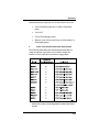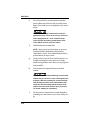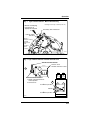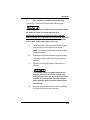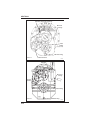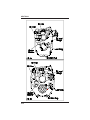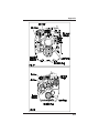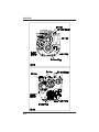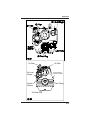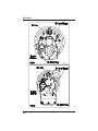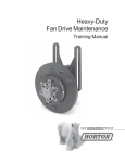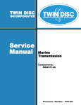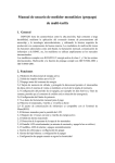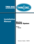
1
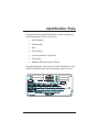
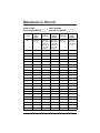
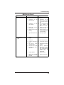
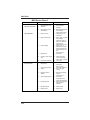
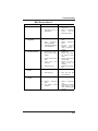
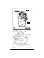
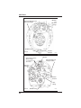
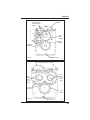
#1016313
Marine Transmission Owner's Manual
NOTICE
Twin Disc, Incorporated makes no warranty or guaranty of any
kind, expressed, implied or otherwise, with regard to the
information contained within this manual. Twin Disc,
Incorporated has developed this manual through research and
testing of the information contained therein. Twin Disc,
Incorporated assumes no responsibility for any errors that may
appear in this manual and shall not be liable under any
circumstances for incidental, consequential or punitive damages
in connection with, or arising out of, the use of this manual. The
information contained within this manual is subject to change
without notice.
#1016313
Marine Transmission
Owner’s Manual
Revision 5
February, 2008
i
Parent Company
Twin Disc, Incorporated
1328 Racine Street
Racine, Wisconsin 53403
U.S.A
Phone +1 (262) 638-4000
Fax +1 (262) 638-4481
Web site : www.twindisc.com
Subsidiaries
Twin Disc, Incorporated
Latin America Office
11700 NW 101 Rd.. Suite 19
Medley, Florida 33178 U.S.A.
Phone +1 (305) 887 9050
Fax +1 (305) 887 9090
Twin Disc (Pacific) PTY. LTD
(Brisbane – Main Office)
40 Telford Street
Virginia, Queensland 4014
Australia
Phone +61 (7) 3265 1200
Fax +61 (7) 3865 1371
Twin Disc International S.A.
Chaussée de Namur, 54
B-1400 Nivelles
Belgium
Phone +32 (67) 887 211
Fax +32 (67) 887 333
Twin Disc (Pacific) PTY. LTD
(Perth - Western Australia Branch)
130a Radium Street
Welshpool WA.6106
Australia
Phone +61 89 355-3033
Fax +61 (7) 3865-1371
Twin Disc s.r.l.
Via S. Cristoforo, 131
40017 S. Matteo Della Decima (BO)
Italy
Phone +39 (051) 6819711
Fax +39 (051) 6824234 or 6825814
Twin Disc (Far East) LTD
40 Lok Yang Way
Jurong
Singapore 628643
Phone +65 6267 0800
Fax +65 6264 2080
ii
Twin Disc Inc.
(Representative Office)
Room 21G, Ai He Mansion
629 Ling Ling Road
Shanghai, China 200 030
Phone +86 (21) 6427 3212 or 14
Fax +86 (21) 6427 5192
Twin Disc s.r .l.
European Propulsion Group
Via dei Calzolai 92
I-55040 Capezzano Pianore (LU)
Italy
Phone +39 (0584) 969696
Fax +39 (0584) 969692
Identification Plate
Transcribe the following information from your unit’s nameplate to
the illustration below for ease of reference.
•
Model Number
•
BOM Number
•
Ratio
•
Serial Number
•
Customer Number (if applicable)
•
Oil Capacity
•
Minimum Oil Pressure when Cruising
Keep this information at hand and refer to the model number, serial
number and BOM number when requesting any parts or service.
iii
Lubrication Plate
Fill in the blanks below with the information from your unit’s
lubrication data plate. Keep this information at hand and refer to it
when servicing your transmission.
MARINE TRANSMISSION LUBRICANT
See the Lubrication Plate on your
Marine Transmission for Oil Specs
START
-UP
STEADY OPERATION
VISCOSITY
MIN.
MIN.
MIN.
MIN.
INCO RPORATED
RACINE, WI. 53403, U.S.A.
Oil temperature listed is temperature of oil to the heat exchanger.
NOTE: Some MG6000 series transmissions built before 2002 do not
utilize a lubrication data plate. See Section 2.4 for oil recommendations.
iv
Maintenance Record
MODEL NUMBER___________________SERIAL NUMBERS___________________
DATE PLACED IN SERVICE__________ DATE/HRS AT OVERHAUL_____________
Check Oil
Level
Grease Oil
Seals
(if appl)
Change Oil
and Filter
Clean
Suction
Strainer
Check Heat
Exchanger
Check
Input
Coupling
Daily
Every 100
hours
New-50 hrs,
then every
1000 hrs.
Rebuilt - 8
hrs, then
1000 hrs
New-50 hrs,
then every
1000 hrs.
Rebuilt - 8
hrs, then
1000 hrs
Every 30 90 days
First 100
hrs, then
every 2000
hrs.
vi
Table of Contents
Marine Transmission
Owners Manual
Section 1
Introduction
1.1
General Information ................................................................. 1-1
1.2
Safety and General Precautions .............................................. 1-1
A.
General ....................................................................... 1-1
B.
Important Safety Notice ............................................... 1-1
1.3
Preventative Maintenance ........................................................ 1-2
1.4
Ordering Parts and Obtaining Service ...................................... 1-2
A.
Ordering ...................................................................... 1-3
B.
Source of Service Information ...................................... 1-3
C.
Warranty Information ................................................... 1-3
Section 2
Description and Specifications
2.1
Description .............................................................................. 2-1
2.2
Construction Features ............................................................. 2-2
A.
Oil Pump Drive ............................................................ 2-2
B.
Lubrication Features .................................................... 2-2
C.
Suction Screen ........................................................... 2-2
D.
Filter Assembly ........................................................... 2-2
2.3
Specifications .......................................................................... 2-2
2.4
Oil Recommendations ............................................................. 2-3
A.
Oil Viscosity ............................................................... 2-3
B.
Oil Pressure and Temperature ..................................... 2-4
C.
Heat Exchanger .......................................................... 2-5
vii
Section 3
Operation
3.1
Selector Valve ......................................................................... 3-1
A.
General Description ..................................................... 3-1
B.
Safety .......................................................................... 3-2
3.2
Prestart-up Checks ................................................................. 3-2
3.3
Start-up ................................................................................... 3-3
3.4
Normal Operation .................................................................... 3-4
3.5
Operation in “Dirty” or Debris Filled Waters ............................. 3-5
3.6
Operation with Optional Trolling Valve ...................................... 3-5
A.
General ....................................................................... 3-5
B.
Operating Limits .......................................................... 3-6
C.
Normal Operation (Trolling Mode) ................................ 3-7
3.7
Windmilling/Backdriving and Towing ........................................ 3-8
3.8
Emergency Operation ........................................................... 3-10
A.
Mechanical Stop on Failed Torsional Coupling .......... 3-10
B.
Come-Home Screws ................................................. 3-10
1.
Description ................................................ 3-10
2.
Table: Transmissions with
3.
Using Come-Home Screws ....................... 3-12
Come-Home Screws ................................ 3-11
C.
Electric Selector Manual Override ............................. 3-16
1.
Determine Your Electric Selector Type ...... 3-16
2.
Type 1 Selector - Installation of
Override Plug ........................................... 3-19
3.
Type 2 Selector - Manual Override Lever ... 3-20
4.
Type 3 Selector - Manual Direction
Control Valve ............................................ 3-21
viii
Section 4
Maintenance
4.1
4.2
General Maintenance .............................................................. 4-1
A.
Oil Level Check ........................................................... 4-1
B.
Lubrication .................................................................. 4-1
C.
Filter and Oil Change Interval ...................................... 4-1
D.
Oil Capacity ................................................................ 4-3
E.
Heat Exchanger Check ............................................... 4-3
F.
Suction Strainer ........................................................... 4-3
G.
Flexible Input Coupling ................................................ 4-3
H.
Bearing Inspection and Replacement .......................... 4-4
I.
Overhaul Interval .......................................................... 4-4
Storage Maintenance Procedures............................................ 4-4
A.
Short Term Storage (Less than One Year) ................... 4-4
B.
Long Term Storage (More than One Year) .................... 4-5
C.
Heat Exchanger Storage ............................................. 4-6
Section 5
Troubleshooting
5.1
Troubleshooting Tables ............................................................ 5-1
Standard Transmission Charts ................................................ 5-2
MGX Series LED Chart ............................................................ 5-8
MGX Transmission Charts ....................................................... 5-9
Section 6
Appendix
6.1
Accessories and Optional Equipment ..................................... 6-1
6.2
Marine Transmission Illustrations ............................................ 6-3
Speed Pick-Up Location .......................................................... 6-3
6.3
Commercial Transmission Warranty .................................... 6-19
6.4
Pleasure Craft Transmission Warranty .................................. 6-21
ix
x
Introduction
Section 1
Introduction
1.1
General Information
This publication provides general operating information for Twin
Disc Marine Transmissions. Specific product details and
performance characteristics can be obtained by contacting your
nearest Twin Disc Authorized Distributor or Service Dealer.
This manual is current at the time of printing. When required,
changes are made to reflect advancing technology and improvements in state of the art.
1.2
A.
Safety and General Precautions
General
All personnel servicing this equipment should employ safe operating
practices. Twin Disc, Incorporated will not be responsible for
personal injury resulting from careless use of hand tools, lifting
equipment, power tools, or unaccepted maintenance/working
practices.
B.
Important Safety Notice
Because of the possible danger to person(s) or property from
accidents that may result from the use of machinery, proper installation, maintenance and operation procedures must be followed. Twin
Disc, Incorporated will not be responsible for personal injury
resulting from careless maintenance/working practices.
1-1
SECTION 1
Inspect as necessary to assure safe operations under prevailing
conditions. Proper guards and other safety devices that may be
specified in safety codes should be provided. These devices are
neither provided by nor are they the responsibility of Twin Disc,
Incorporated.
Selecting NEUTRAL disengages transmission clutches but does
not prevent propeller shaft rotation. If you require positive
neutral (propeller shaft locked), a shaft brake or other shaftlocking device must be used.
To prevent accidental starting of the engine when performing
routine transmission maintenance, disconnect battery cables
and remove ignition key from the switch.
1.3
Preventative Maintenance
Frequent reference to the information provided in this manual
regarding daily operation and limitations of this equipment will assist
in obtaining trouble-free operation. Schedules are provided for
recommended maintenance of the equipment in Section 4 of this
manual, as well as a chart in the Appendix, Section 6.
1.4
Ordering Parts and Obtaining Service
All replacement parts or products (including hoses and fittings)
must be of Twin Disc origin or equal, and otherwise identical
with components of the original equipment. Use of any other
parts or products will void the warranty and may result in
malfunction or accident, causing injury to personnel and/or
serious damage to the equipment.
1-2
Introduction
A.
Ordering
Renewal parts, service parts kits, optional equipment and product
service assistance may be obtained from any authorized Twin Disc
distributor or service dealer. Contact Twin Disc for the distributor
or service dealer near you.
Twin Disc, having stipulated the bill of material number on the unit’s
nameplate, absolves itself of any responsibility resulting from any
external, internal, or installation changes made in the field without
the express written approval of Twin Disc. All returned parts, new
or old, emanating from any of the above stated changes will not be
accepted for credit. Furthermore, any equipment that has been
subjected to such changes will not be covered by a Twin Disc
warranty.
B.
Source of Service Information
For the latest service information on Twin Disc products, contact
any Twin Disc distributor or service dealer. Product service manuals
are available, which provide more specific and detailed overhaul
and installation instructions. Provide your model number, serial
number and bill of material number to obtain information on your
unit.
C.
Warranty Information
The Commercial Twin Disc marine transmission warranty can be
found in the Appendix, Section 6.3 of this manual. The Pleasure
Craft Twin Disc marine transmission warranty can be found in the
Appendix, Section 6.4 of this manual. This warranty may be
supplemented by additional published warranty terms dependent
upon the product involved. Supplementary warranty terms are
available upon request. For details on administering the warranty,
contact any Twin Disc distributor, service dealer or the Warranty
Administration Department, Twin Disc, Incorporated, Racine,
Wisconsin, U.S.A.
1-3
SECTION 1
NOTES
1-4
Description and Specifications
Section 2
Description and Specifications
2.1
1.
Description
While most Twin Disc marine transmissions are forward/
reverse reduction units, some units provide speed-increasing capability. All may be used with standard (right-hand)
rotation engines and certain models may be modified to
accommodate nonstandard (left-hand) rotation engines.
Contact your Twin Disc distributor if you anticipate using
nonstandard engines.
NOTE: Engine direction of rotation is determined by facing
the front of the engine (opposite engine flywheel). From this
viewpoint, clockwise crankshaft rotation is defined as righthand rotation.
2.
All current Twin Disc marine transmissions can be operated
through either primary or secondary clutch at full-rated
horsepower for forward (ahead) propulsion using standard
engines. Contact your Twin Disc distributor for the rated
horsepower if you anticipate using nonstandard engines.
NOTE: The primary clutch has the shortest power path
through the transmission. The secondary shaft is driven in
opposite rotation by the primary shaft.
3.
Transmission clutches are hydraulically applied using
regulated oil pressure. All bearings, clutches and gears are
lubricated and cooled with oil.
2-1
SECTION 2
2.2
A.
Construction Features
Oil Pump Drive
For most transmissions, the secondary clutch shaft drives the oil
pump. One exception is the MG540, having two pumps—one
driven by the primary shaft and one driven by the secondary shaft.
B.
Lubrication Features
The transmission case serves as the reservoir (sump) for all oil used
in the transmission. Bearings and clutches on the primary and
secondary shafts are lubricated and cooled through passageways in
the shafts. Output shaft bearings are gravity and/or splash lubricated. Some transmissions use pressurized oil spray to lubricate
gears and bearings.
C.
Suction Screen
All units have a suction strainer located between the sump and oil
pump in the hydraulic circuit. Its purpose is to prevent debris from
entering the inlet side of the pump. The suction strainer must be
cleaned as a part of every oil change. Consult the illustrations found
in Section 6.2 for the suction strainer location on your unit.
D.
Filter Assembly
Many units have an oil filter installed in the system. Some units
incorporate a spin-on filter. Other units use a cartridge type filter
plumbed into the hydraulic circuit between the pump outlet and the
transmission inlet port. Replace oil filter as part of every oil change.
Consult the illustrations found in Section 6.2 for the filter location on
your unit.
2.3
Specifications
All Twin Disc marine transmissions are equipped with an identification plate. (See sample identification plate at the front of this
manual.) In addition to information identifying the unit (i.e. model
number, BOM number, ratio, serial number and customer number),
2-2
Description and Specifications
the identification plate provides information on oil capacity, minimum
cruise oil pressure and oil check/oil change intervals for your
particular transmission. All operators of this equipment are responsible to read and apply the information provided on the transmission
identification plate.
2.4
A.
Oil Recommendations
Oil Viscosity
See your unit’s lubrication data plate for type of oil and
viscosity recommendations. Transcribe the information from your
transmission’s lubrication data plate to the sample plate found at the
front of this manual for ease of reference.
MG6000 SERIES ONLY: Some MG6000 series units that were
manufactured prior to 2003 do not utilize a lubrication data plate. The
recommended oil for these units is SAE 40W. Use only SAE-API
service class CD engine oil that is certified by the vendor to pass TO2 or C-3 test specifications.
Multi-viscosity oils (i.e. 15W-40 etc.), automatic transmission
fluid (ATF) and synthetic oils are not approved for use in Twin
Disc marine transmissions without written approval from Twin
Disc.
2-3
SECTION 2
B.
Oil Pressure and Temperature
All units have provisions to install oil pressure and oil temperature gauges. Oil pressure gauges are recommended for all
installations. By monitoring “main” oil pressure and temperature, you detect problems before major damage to the unit
occurs.
Your unit’s identification plate specifies “minimum oil pressure when
cruising.” This specification is the “main” oil pressure measured with
the oil temperature in the normal operating range and engine speed
at approximately 2/3 throttle setting. It is suggested that an alarm
system be installed to notify the operator in the event that the oil
pressure falls below the “minimum pressure when cruising” specification.
If you detect abnormal oil pressure:
1.
Verify that the pressure reading is accurate. (Gauges can fail
or malfunction.)
2.
If gauge is malfunctioning, determine that actual operating
pressure is within allowable range before resulting operation.
3.
If pressure reading is accurate and pressure is outside of the
allowable range, shut down the engine and correct the
problem. See troubleshooting procedures in Section 5 of
this manual.
NOTE: If problem cannot be corrected and engine must be
shut down, see instructions for windmilling/backdriving and
towing in Section 3.6 of this manual.
If unit must be kept in operation to prevent injury to personnel or damage to equipment, operate at lowest power
possible until unit can be safely shut down.
2-4
Description and Specifications
C.
Heat Exchanger
The heat exchanger is required to maintain the oil temperature in the
hydraulic system within the recommended operating range. Proper
oil temperature is maintained by passing coolant through the heat
exchanger.
Some models, such as the MG5300 series and MG6000 series
transmissions, may have an integral heat exchanger. On models with
a remote mounted heat exchanger, the heat exchanger should be
installed in a location convenient to coolant and marine transmission
oil. See your unit’s lubrication plate for operating oil temperature ranges and the recommended viscosity for each.
2-5
SECTION 2
NOTES
2-6
Operation
Section 3
Operation
3.1
A.
Selector Valve
General Description
A selector valve controls application of forward or reverse clutches
in Twin Disc marine transmissions. In most transmissions a leveractuated mechanical valve with detented positions for FORWARD,
NEUTRAL and REVERSE is used. An electric, solenoid-operated
valve is available as an option for certain transmissions and is
standard equipment on other transmissions. The mechanical and
solenoid operated valves both perform two functions: selecting
FORWARD, NEUTRAL and REVERSE, and controlling main
(clutch apply) pressure.
Omega® units, the MG530M and MG514M, use a mechanical
selector valve actuated by a sprocket wheel to select FORWARD,
NEUTRAL and REVERSE, and to control pressure applied to the
selected clutch.
Most transmissions incorporate a rate-of-rise system that causes
clutches to engage at a lower pressure, then progressively increases
pressure to lock up the clutch. This results in smooth clutch engagement and minimizes shift shock.
Control Systems that fail to place a mechanical selector valve
in detented positions will damage or cause failure of the clutch
packs.
Manually holding the shift selector out of the detented position
will also damage or cause failure of the clutch packs.
3-1
SECTION 3
Control systems for units equipped with electric solenoid valves
must NOT permit actuation of both forward and reverse solenoids at the same time.
B.
Safety
Whenever maintenance is performed on the marine transmission or
control valve, always assure that the transmission control are free
and are adjusted properly. Be certain that the transmission range
selected at the operator’s station places the control valve in the fully
detented position for the selection made.
3.2
Prestart-up Checks
Prior to starting the engine, check the transmission as follows.
1.
Check that there is oil in the transmission.
NOTE: This check will determine that there is oil in the
transmission but will not determine if oil level is correct. Oil
level check must be performed with engine operating at low
idle with transmission in neutral and oil temperature in
operating range.
3-2
2.
Check transmission for leaks, cracks and obvious damage.
3.
Check mountings for tightness or damage such as cracks.
Tighten loose mountings and replace damaged parts.
4.
Inspect heat exchanger oil and coolant lines and hoses for
leaky connections, kinks, cracks and other damage. Replace damaged lines and/or hoses.
5.
Check pressure and temperature gauges where applicable.
6.
Inspect driveline and input and output shaft oil seals for
signs of leakage. Replace parts as required.
7.
Inspect unit identification plate and lubrication plate for
looseness and corrosion. Tighten mounting screws that are
loose and replace corroded plates.
Operation
NOTE: Should you need to replace a plate, assure that all
pertinent information is transcribed to the new plate. Failure
to do so could result in the loss of important information
necessary to obtain parts and service.
3.3
Start-up
1.
Assure that transmission control is in NEUTRAL.
2.
As soon as engine starts, check transmission oil pressure
(oil pressure gauges are recommended for all installations).
Pressure should register within 15 seconds. If no pressure is
indicated, stop engine and determine cause.
3.
Check oil level as follows.
A. Fill transmission to “low” mark on dipstick. Run engine
at idle until oil temperature reaches operating range.
B. Continue running at idle and check oil level with oil level
gauge (dipstick). Level should be at “full” mark on gauge.
Add or remove oil as necessary to bring level to “full” mark
on gauge.
C. Allow oil to cool (perhaps overnight). Check the oil
level while cold at low idle engine speed while in neutral.
Make note of this adjusted cold oil “full” level for
future reference. DO NOT OVERFILL.
3-3
SECTION 3
3.4
Normal Operation
1.
For maximum service life, make all shifts from NEUTRAL
into either FORWARD or REVERSE with engine running at
low idle.
2.
When a shift range is selected, assure that the control lever
is in the fully detented position for the range selected.
3.
Monitor transmission oil pressure and temperature. See oil
pressure information on identification plate and oil temperature information on lubrication plate.
NOTE: Sustained operation of the marine transmission with
oil temperature outside of normal operating range is not
recommended.
4.
Shifting Limits
The following chart contains the recommended engine rpm
for all shifts (NEUTRAL into FORWARD or REVERSE,
and FORWARD or REVERSE through NEUTRAL into the
opposite direction) for all Twin Disc marine transmission
models:
Model
Maximum Engine Speed for Shifting
MG 340, MG 360, MG 5005A,
MG 5012SC MG 5015A,
MG 5020SC, MG 5055A:
All shifts 900 rpm maximum.
MG 540, MG5600 Series:
All shifts 750 rpm maximum.
MG 6000 Series: (except MG 6650,
MG 6690, and MG 6848):
50% of engine rated operating speed.
All other models:
All shifts 1000 rpm maximum.
NOTE: The recommended engine rpms pertain to normal
operation only. In an emergency, the owner/operator is
expected to employ whatever procedures are necessary to
prevent loss of life and reduce damage to property.
3-4
Operation
3.5
Operation in “Dirty” or Debris Filled Waters
Operation in waters that contain debris such as logs, ropes, or
cables must be done cautiously. The engines should be throttled
back to near idle to prevent damage to the propellers, drivelines,
and transmissions.
Getting a rope (or similar object) caught in the propeller, or
“propeller Strikes” can cause serious damage to the Marine
Transmission. If the vessel gets a rope (or similar object)
caught in the propeller, or the propeller strikes an object, the
engine should be shut down and a visual inspection of the
Marine Transmission should be conducted. If in doubt, the
transmission should not be operated. Follow the towing or
back-driving procedures outlined in the manual to reach port.
Continued operation of the transmission after getting a rope
(or similar object) caught in the propeller, or a severe propeller strike may cause further damage to the transmission and
place the safety of vessel and crew in jeopardy.
3.6
A.
Operation with Optional Trolling Valve
General
Trolling valves are available as optional equipment for most Twin
Disc marine transmissions. The trolling valve allows reducing and
controlling propeller speed below that normally attained by operating the engine at low idle. Examples of operations requiring such
slow speeds are trolling or movement through “no wake” restricted
areas.
Most trolling valve can be used with the selector valve in either the
forward or reverse positions. Actuating the trolling valve reduces
clutch apply pressure, which reduces propeller speed.
3-5
SECTION 3
B.
Operating Limits
The following chart lists the maximum engine speeds for marine
transmissions to operate in the trolling mode. Continuous trolling is
permitted if engine speed does not exceed prescribed limits.
NOTE: Additional cooling is not required when in the trolling mode but
trolling valve performance can be affected by operating oil temperature. In some cases a thermostatic bypass valve is recommended to
maintain operating oil temperature at desired level.
Marine Transmission
MG 5005A
MG 5012SC
MG 5020SC
Maximum Engine Speed with
Transmission in the Trolling Mode
1200 RPM Engine Speed
MG 5015A
MG 5055A
MG502 Series
Up to 42% of full load RPM, but not below
500 RPM or above 1100 RPM engine speed.
MG5010 Series
MG509
MG5011 Series
MG5090A
MG506 Series
MG5091
MG507 Series
MG5111 Series
MG5075 Series
MG5112V
MG5081
MG5113
MG5050 Series
MG514C
MG5061 Series
MG5141 SC
MG5062V
MG516
MG5082
MG5170DC
MG5085
MG518
1100 RPM or 40% of full load RPM,
whichever is smaller.
1100 RPM or 60% of full load RPM,
whichever is smaller.
MG(X)5114 Series MG520
MG(X)5135
MG5200 series
MG(X)5145
MG5301
MG540
MG5600 Series
MG 6650
MG 6690
MG 6848
Other
MG6000 Series 800 RPM.
3-6
1000 RPM or 50% of full load RPM,
whichever is smaller.
Operation
C.
Normal Operation (Trolling Mode)
The following is the normal procedure for engaging and operating a
marine transmission when trolling mode is to be used.
1.
Shift transmission selector to NEUTRAL.
2.
Reduce engine rpm to low idle.
3.
Move trolling valve control lever out of detented “no troll”
position to “maximum troll” (slowest vessel speed) position.
4.
Move transmission selector lever to desired direction of
travel.
5.
Adjust trolling valve lever setting (and if necessary, engine
rpm) up to specified limit to attain desired vessel speed.
Do not exceed specified maximum engine speed while operating in the troll mode. To do so will result in excessive clutch
heat buildup and possible clutch failure.
The trolling valve must be in the detented “no troll” position
when docking the vessel or when operating in congested
areas. Failure to do so could result in sluggish response to
power changes or shift reversals with loss of necessary control
of vessel speed or direction of travel.
NOTE: Do not attempt to use a marine transmission equipped with a
trolling valve as a “power dividing” device. The capability to run the
engine at a constant rpm to power accessories (pump, generators,
compressors, etc.) while maintaining independent control of output
shaft speed can be adequately accomplished by Omega® type drives
only (e.g., MG530M, MG514M). Attempts to use a trolling valve
equipped transmission for such a purpose at engine speeds above the
limits specified will result in clutch failures.
3-7
SECTION 3
6.
To return to “no troll” operation
a.
Move trolling valve control lever to detented “no troll”
position.
b.
Resume “normal” no troll operations.
NOTE: Moving the trolling valve control lever to the “no
troll” position while engine speed is at the high limit for
trolling operations will cause an abrupt change in
propeller (and vessel) speed. Reducing engine speed
to idle before selecting “no troll” will result in a
smoother transition to “no troll” operation.
Assure that the trolling valve cable control system is adjusted
properly. The trolling valve control lever on the transmission
must be in the detented no troll position when the control at the
operator’s station is moved into the “no troll” position. Failure
to do so could result in inadequate response to power and/or
direction changes, endangering personnel and equipment.
3.7
Windmilling/Backdriving and Towing
“Backdriving” occurs when an engine is shut down and the propeller shaft is being “driven” by the flow of water across the propeller.
This is sometimes referred to as “windmilling.” The propeller shaft is
rotating components in the marine transmission. Locking the propeller shaft in place will prevent backdriving.
Situations where backdriving may occur:
3-8
•
Vessel being towed for any reason.
•
Multiple-transmission vessel with one or more engines shut
down while under way.
•
Sailboat under way with auxiliary engine shut down.
•
Vessel tied up or docked in heavy current.
Operation
Most current Twin Disc production marine transmissions (with the
exceptions that follow) can be backdriven in the situations listed.
Vessel speed under all towing or backdriving conditions must not
exceed the normal propulsion speed of the vessel.
Do not exceed normal vessel speed during backdriving. Oil
sump temperature must not exceed 100oC. Damage will occur
to internal components. If oil temperature increases to 100oC,
reduce temperature either by reducing backdriving speed, or
supplying additional cooling with water flow or by idling the
engine.
The following backdriving (towing) options are applicable to all
transmissions except MG5170 series, MG5200 series, MG5300
series, MG5600 series, and all MG6000 series (without the
optional trailing pump). For these transmissions, instructions in only
B and C below are applicable.
You need to employ only one of the following methods:
A.
Start the engine and operate the marine transmission in
neutral at normal fluid pressures for five minutes, doing this
once every eight hours. Maintain the backdriven marine
transmissions oil level at the full mark on the dipstick.
B.
Lock the propeller shaft to prevent rotation.
C.
Add a trailing pump to the lube circuit. See the hydraulic
system prints for more details on auxiliary pump specifications for the applicable transmission or contact your Twin
Disc distributor.
D.
In the case of an inoperable engine, or pump failure, where
pressure lubrication of the transmission is not possible; plug
the dipstick tube and completely fill the transmission with
oil. Prior to backdriving or towing, drain the oil down to
“full” oil level. Repeat this process every eight hours.
3-9
SECTION 3
3.8
Emergency Operation
A.
Mechanical Stop on Failed Torsional Coupling
Many torsional couplings used with Twin Disc transmissions
have mechanical stops to allow power to be transmitted to the
transmission in the event of a coupling failure. Continued
operation at high power levels could result in costly damage to
the transmission internal components. In the event of a torsional
coupling failure, return to a safe harbor immediately to initiate
repair or replacement of the failed coupling.
Limit operation to 50% of maximum engine speed, or a
maximum of 1000 rpm to avoid additional costly internal
damage to transmission components.
B.
Come-Home Screws
1.
Description
Certain marine transmissions are equipped with come-home
screws that permit mechanical lock-up of a clutch in the event
hydraulic pressure is lost.
Come-home screws are intended to be used on malfunctioning
single-transmission vessels. On vessels with multiple transmissions, if one transmission malfunctions, propel the vessel with
the remaining good transmission as described in the instructions
for windmilling/backdriving (Section 3.6).
In the event of hydraulic pump failure, using the comehome screws to mechanically lock up a clutch will cause
the transmission to operate without pressure lubrication,
which may cause further damage to the transmission. Avoid
using come-home screws unless there is no other means
available to bring the vessel into port.
3-10
Operation
Situations that may require the use of come-home screws are:
2.
•
Loss of hydraulic pump drive or failure of hydraulic
pump.
•
Loss of oil.
•
Cracked clutch-apply piston.
•
Broken, worn, or blown seal rings on clutch shaft(s) or
clutch-apply piston.
Table: Transmissions with Come-Home Screws
The following table shows the marine transmissions that currently incorporate come-home screws in their design, the
number of screws and the tool needed to engage them.
* Not all units in these model designations contain come-home
screws.
3-11
SECTION 3
3.
Using Come-Home Screws
a)
Shut down engine.
Remove ignition key or take whatever action
necessary to prevent accidental engagement of
engine starter. Failure to do so could result in
injury to personnel or damage to equipment.
b)
Lock transmission output shaft to prevent shaft
rotation.
When using come-home screws, the following
factors must be considered:
NEVER engage both clutches at one time. To
do so will lock up the transmission and will
prevent engine start or operation.
Identify and always engage the clutch used
for forward (ahead) propulsion. Failure to
correctly identify the clutch to be engaged
will cause loss of time and may place the
vessel and crew in jeopardy.
c)
Locate come-home screw access plugs in manifold at
rear of transmission. See Section 6.2 for locations.
Remove the two access plugs for the clutch to be
engaged.
Most single-transmission vessels equipped with
standard (right-hand) rotation engines engage the
clutch on the transmission primary shaft for forward
(ahead) propulsion. (Propeller shaft turns in antiengine direction for forward).
Most units equipped with come-home screws have
four screws in each clutch housing that are accessed
through two come-home screw access plug holes in
3-12
Operation
the manifold for each clutch. Two screws can be
tightened at a time. Then the clutch housing must be
turned to provide access to the remaining two
screws.
Some MG509 transmissions are equipped with two
come-home screws in each clutch housing with two
come-home screw access plug holes in the manifold
at each clutch location.
d)
Use a flashlight to look into come-home screw access
plug holes. For most transmissions with come-home
screws, slowly bar engine over to align come-home
screws in clutch housing with access plug holes in
manifold. Models MG514C and MG530 require
barring over the output propeller shaft rather than the
engine.
NOTE: Procedure used to “bar” engine over to align
come-home screws with access plug holes in the
manifold will vary depending upon engine involved,
auxiliary equipment installed, etc. Whatever the
situation, it is necessary to rotate the transmission
clutch housings and to stop rotation when alignment is
achieved. “Bumping” the starter may be possible and
may achieve necessary alignment. Where possible,
using a bar or other device attached to the front of the
engine crankshaft (after releasing engine compression)
is the most effective method for achieving desired
alignment.
3-13
SECTION 3
e)
Use tool specified for your transmission and alternately tighten (turn clockwise) the accessible comehome screws until screws are tightened as far as they
will go.
Assure the accessible come-home screws are
tightened evenly. Failure to do so may cause the
clutch apply piston to “cock” and bind in the
clutch cylinder preventing compression of the
clutch plates and lock up of the clutch.
f)
Unlock transmission output shaft.
NOTE: Steps g) through j) below apply to all except
the MG509 transmission listed in the preceding
“Applicability” section. For the MG509 transmissions,
proceed directly to step k) below.
g)
Use procedure in step d) above and bar engine over
to align remaining two come-home screws in the
clutch housing with the come-home access plug holes
in the manifold.
h)
Lock transmission output shaft to prevent shaft
rotation.
Failure to lock the output shaft may result in shaft
rotation due to current or wave action against the
propeller. With two come-home screws mechanically locking the clutch, such shaft rotation will
cause the clutch housing and the engine crankshaft to turn and could result in injury to personnel and/or damage to equipment.
i)
3-14
Use screwdriver or internal-hex wrench and tighten
remaining two come-home screws as far as they can
go.
Operation
j)
Unlock transmission output shaft
k)
Reinstall plugs in come-home screw access holes in
manifold.
l)
In the case of a pump failure where pressure lubrication of the transmission is not possible, an auxiliary
lube oil pump should be run if available. Otherwise,
plug the dipstick tube and completely fill the transmission with oil. Prior to starting engine, drain the oil
down to “full” oil level. Repeat this process every
eight hours.
Do not start engine after mechanically locking a
transmission clutch before assuring that the
transmission will be adequately lubricated.
Operation of the transmission without sufficient
lubrication will cause bearing and/or gear failure,
placing the safety of vessel and crew in jeopardy.
m)
Start engine and operate at no more than 1/3 throttle.
Transmission cannot be shifted to neutral or
reverse with a mechanically locked up clutch.
Engine must be shut down and vessel placed
under tow before entering any congested area or
dock area. Failure to do so will endanger safety
of vessel and crew as well as others in the area.
3-15
SECTION 3
C.
Electric Selector Manual Override
1.
Determine Your Electric Selector Type
If an electrical power interruption occurs, the electric selector
can be overridden as follows:
a)
Stop the engine.
b)
Based on Figures 1, 2, and 3, determine the type of
electric selector valve used on the transmission.
c)
Go to the following instructions:
• Type 1 (manual override plug) under Section
3.7.C.2
• Type 2 (manual override lever) under
Section 3.7.C.3.
• Type 3 (manual direction control valve) under
Section 3.7.C.4.
3-16
Operation
Fig. 1
Type 1 Electric Selector - Manual Override Plug
Manual override plug
used in place of
appropriate solenoid.
Cartridge Screw Torque = 34 Nm (25 Lbs. Ft.)
Secondary Clutch Solenoid
Primary Clutch
Solenoid
Stored
manual
override
plug. Check
your
model for
exact
location.
om-24
Fig. 2 Type 2 Electric Selector - Manual Override Lever
Electric Control Position
1. Push in lever.
2. Rotate clockwise to lock.
1
Port
Manual Override Position:
1. Rotate counterclockwise to
neutral position.
2. Pull out lever.
Port
A
B
Solenoid
Solenoid
2
Port A lever position.
Neutral
Port B lever position.
om-25
3-17
SECTION 3
3-18
Operation
2.
Type 1 Selector - Installation of Override Plug
Consult Fig. 1 for items referenced in the following steps.
Once the override plug is installed, the transmission cannot
be shifted to neutral, or into the opposite gear.
Shut down the engine and place the vessel under tow
before entering any congested area or dock area. Failure to
do so will endanger the safety of the crew and vessel as
well as other people and vessels in the area.
a)
Locate and remove the stored manual override plug
from the selector valve body for use in step c).
NOTE: The location of the stored override plug varies
on different models.
b)
Determine which clutch should be engaged (primary
or secondary clutch) and remove the appropriate
solenoid.
c)
Install the override plug in place of the removed
solenoid.
The selected clutch is engaged whenever the
engine is running. If the vessel is going in the
wrong direction, stop the engine and remove the
override plug. Reinstall the removed solenoid,
then repeat the above procedure with the opposite solenoid.
d)
Store the removed solenoid where the override plug
was stored until repairs are performed.
3-19
SECTION 3
3.
Type 2 Selector - Manual Override Lever
Type 2 electric selector valves (Fig. 2) have a lever that can be
put into the manual override position. If electrical power is
interrupted, the manual override feature can be used to engage
the clutches.
The control cable must always place the selector lever on
the valve into the detented positions. Operation in an
improper lever position can cause clutch failure.
a)
Rotate the lever to the neutral position (counterclockwise) and pull outward (view 1 in Fig. 2).
b)
Rotate the selector lever to select forward or reverse
(view 2, Fig. 2).
NOTE: Some vessels may have a cable at the operating station that lets the operator manually control
clutch selection when in the manual override position.
c)
Once electrical power is restored to the selector
valve, switch the lever back to electric control.
• Put lever in neutral.
• Push the lever into the valve body. It will be
more difficult to push the lever in if the engine is
running.
• Lock it in place by rotating clockwise.
3-20
Operation
4.
Type 3 Selector - Manual Direction Control Valve
Remove the locking pin from the Manual Direction Control
Valve, and push the valve in to engage Clutch A, or pull it out to
engage Clutch B. Note that the center position is Neutral.
Engagement of a clutch using the Manual Direction Control Valve should only be done with the
engine at idle speed.
3-21
SECTION 3
NOTES
3-22
Maintenance
Section 4
Maintenance
4.1
General Maintenance
NOTE: A chart is provided in the front of the manual to record
the dates/hours that maintenance procedures are performed.
A.
Oil Level Check
Check oil level daily or every 10 hours of engine operation.
Check with engine running at low idle and with marine transmission in neutral. Transmission oil temperature should be in
normal operating range prior to checking oil level. See Section
3.3, Start-Up.
B.
Lubrication
If your unit is equipped with a lubrication fitting, grease the oil
seals at the output end of the transmission output shaft with
water pump grease through the lubrication fitting. See illustrations in Section 6.2 for location of the lubrication fitting. Apply
grease every 100 hours or when boat is docked. No other
lubrication is required.
NOTE: Preferred grease is one with lithium soap, NLGI consistency
#2 for component temperatures above 20° C (68° F).
C.
Filter and Oil Change Interval
With a new transmission, change the oil and filter element
within first 50 hours of operation. Change oil and filter element
after each 1000 hours of operation, or six months, whichever
comes first. The oil may need to be changed more frequently if
conditions warrant.
4-1
SECTION 4
For a rebuilt transmission, check the suction screen and filter
element after eight hours of operation. Look for lint or other
material that may collect from rags or towels used in the parts
cleaning process. Look for chips or shavings particularly if the
transmission has had a problem that caused debris in the
system. (For units with spin-on filters, this will require cutting
the filter element apart to access the element core.) If the filter
is clean, install a new filter element and then change the oil and
filter element after 1000 hours of service. If the filter is dirty,
change the element and operate for another eight hours. Check
the filter again. Continue this cycle until the filter is clean and
then change the oil and filter after 1000 hours of service or
more often if conditions warrant.
NOTE: Situations involving debris in the hydraulic system will
require that heat exchangers and all connecting lines and hoses be
thoroughly cleaned. If the heat exchanger cannot be disassembled, or
if it cannot be assured that all debris is removed, the heat exchanger
should be replaced.
Draining
Drain the transmission by removing the oil drain plug from the
rear/bottom of the transmission. See illustrations in Section 6.2
or service literature for your transmission for location of
transmission and filter drain plugs.
NOTE: Dispose of used oil and oil filters in accordance with federal,
state or local laws. Exercise precautions to prevent environmental
contamination during any transmission servicing procedure.
Filling
1. Remove the breather or the oil fill closure from the top
of transmission case.
2.
4-2
Pour new oil through breather or closure opening. Fill
with recommended clean oil, taking necessary precautions to prevent entry of dirt or debris. (See lubrication
plate on transmission and information transcribed to the
front of this manual for additional oil information.)
Maintenance
D.
Oil Capacity
See lubrication plate. Capacity given will be internal quantity
required to fill transmission to proper level, but may NOT
include quantity to fill external hoses and heat exchanger.
Check oil level per Section 3.3 Start-Up.
E.
Heat Exchanger Check
Heat exchangers furnished by Twin Disc to be used for salt
water applications have zinc rods installed at the inlet and
outlet heads. These rods must be checked every 30 to 90 days
depending on coolant conditions, pH factor, salinity, etc. If
over one half of the rod is disintegrated, it should be replaced
to provide effective protection.
Excessive corrosion of the zinc rod indicates electrolytic
action. A careful inspection should be made to determine if this
action is caused by a short circuit or external grounded electric
current. These conditions must be eliminated to avoid frequent
replacement of the zinc rods. If these conditions do not exist, it
is evident that the corrosion is due to local electrolysis. If rods
are corroded with foreign material, they should be cleaned with
a wire brush.
F.
Suction Strainer
Remove and clean the suction strainer at every oil change or
sooner if necessary. See illustrations in Section 6.2 for location.
G.
Flexible Input Coupling
Do not obstruct the flywheel housing vents preventing the free
flow of air for cooling the coupling. Life of the coupling may
be reduced if the ambient temperature of the air around the
coupling is outside the operating range. Operating air temperatures above -6°C (22°F) and below 82°C (180°F) should be
maintained.
If possible, visually inspect the coupling after the first 100 hours of
operation and every 2000 hours thereafter, or every six months,
4-3
SECTION 4
whichever comes first. Torsional vibration, misalignment, degradation by contaminants (oil), heat, ultraviolet radiation, and excessive
system torque can cause cracks or other signs of distress to appear
on the surface of the rubber. The above-described items affect the
life of the coupling element.
If coupling access is restricted, inspection may be possible only at
engine overhaul or whenever the transmission is separated from the
engine. On such units, frequently check the flywheel housing vents.
Coupling deterioration, from a variety of causes may be indicated
by an accumulation of residue at the vents. Should this be evident,
inspect to determine the cause.
H.
Bearing Inspection and Replacement
At the engine overhaul interval, or more frequently, inspect all
transmission bearings and replace as necessary.
I.
Overhaul Interval
Overhaul the transmission at the same time the engine is overhauled.
4.2
Storage Maintenance Procedures
It is sometimes necessary to store Twin Disc transmissions or
boats equipped with Twin Disc components. In order to prevent corrosion damage, the following procedures are recommended:
A.
Short Term Storage (Less than One Year)
Transmission installed in a boat on an engine that can be run.
(Boat in the water.)
4-4
1.
To the extent possible, store boat in a location that
minimizes exposure to the elements.
2.
Prior to storage, drain oil and refill to full level on the
dipstick with recommended new oil. Install new filter,
if applicable. After changing oil and filter, run engine
Maintenance
long enough to bring oil to operating temperature and
operate transmission in all ranges. Shut down.
3.
Use only recommended oils to maintain proper levels. Do
not use preservative-type oils.
4.
Every three months, check oil level and availability of
coolant. Start engine and run at approximately 1000
rpm to bring oil temperature up to normal operating
range. Run engine at least five minutes, shifting into
each range and shut down.
5.
Drain and refill with recommended oil and change
filters, if applicable, prior to returning unit to regular
service.
6.
Check the condition of the zinc rods in the heat exchanger according to Section 4.1.E.
B.
Long Term Storage (More than One Year)
Transmission installed in a boat where the engine cannot be
run. (Boat out of water.)
1.
Use standard recommended oil for the following procedures:
Once each year, remove dipstick and plug dipstick tube.
Completely fill the transmission with oil. Rotate the
output shaft at least five revolutions. Partially drain oil,
reinstall dipstick, and then drain oil down to full mark
on the dipstick.
2.
Seal breather, dipstick tube and all other openings with
waterproof tape.
3.
Grease exposed members that are subject to corrosion.
4.
Every three months rotate output shaft four or five
revolutions.
4-5
SECTION 4
C.
5.
Tag transmission to show date it was placed in storage and
current status relating to storage procedure.
6.
To remove from storage and place in regular service:
a.
Remove waterproof tape from breather, dipstick tube
and all openings.
b.
Drain oil and remove oil filter.
c.
Install new oil filter and fill transmission with new
recommended oil to full mark on dipstick.
d.
Replace zinc rods in heat exchanger.
Heat Exchanger Storage
When storing a heat exchanger, oil and water ports must be
kept sealed. Heat exchangers stored during cold weather must
have the water chamber drained to prevent freezing. Take
precautions to prevent damage from freezing and corrosion.
4-6
Troubleshooting
Section 5
Troubleshooting
5.1
Troubleshooting Tables
The following charts are intended as a guide for determining the cause of problems that could be encountered and
the corrective actions for those difficulties.
The transmission is one part of a complete propulsion
system. Problems before the transmission (in the engine)
or after the transmission (in the output shaft or propeller)
can cause problems to develop in the transmission. It is
important that the entire propulsion system be considered
when transmission problems are encountered.
Note that there are three separate charts on the following
pages.
o Troubleshooting charts for Standard MG Marine
Transmissions
o LED Troubleshooting chart for MGX Series of Marine
Transmissions
o Troubleshooting charts for MGX Series of Marine
Transmissions
Note: Troubleshooting assistance, as well as
maintenance, repair and parts service is
available from your Twin Disc distributor or
service dealer.
5-1
SECTION 5
Standard MG Chart 1
5-2
Troubleshooting
Standard MG Chart 2
5-3
SECTION 5
Standard MG Chart 3
5-4
Troubleshooting
Standard MG Chart 4
5-5
SECTION 5
Standard MG Chart 5
Symptom
6. No neutral. (Neutral
selected, but boat
continues to move.)
7. Harsh engagement.
Cause
Remedy
6-1 Clutch plates
warped.
6-1 Overhaul unit and
replace clutch plates.
6-2 Control valve
incorrectly indexed.
6-2 Check and adjust
control linkage.
6-3 Worn seal rings.
6-3 Check clutch apply
pressure. Replace
seal rings as
necessary.
6-4 Broken or faulty
clutch linkage.
6-4 Repair control
linkage.
7-1 Regulating piston or
rate-of-rise piston
stuck.
7-1 Disassemble control
valve. Clean parts.
Replace parts if
necessary.
7-2 Orifice plate ball in
control valve not
seating properly.
7-2 Remove orifice
plate cover. Clean
parts. Replace parts
if necessary.
7-3 Engine speed too
high.
7-3 Reduce engine
speed.
Tbl-003
5-6
Troubleshooting
Standard MG Chart 6
Symptom
8. Low lube oil pressure.
9. Oil escaping from
breather.
Cause
Remedy
8-1 Pump GPM output
too low.
8-1 Replace pump.
8-2 Pump suction
strainer plugged.
8-2 Remove, clean,
inspect and install
the suction screen.
8-3 Air leak on suction
side of pump.
8-3 Inspect and correct
cause of suction
leak.
8-4 Lube regulator
valve stuck.
8-4 Remove and clean
or replace parts as
necessary.
8-5 Broken piston rings.
8-5 Replace damaged
piston rings.
9-1 Oil level too high.
9-1 Adjust oil level.
9-2 Wrong type of oil.
9-2 Drain and refill with
recommended oil.
Tbl-003
5-7
SECTION 5
MGX Series LED Chart
L ig ht S ta tu s
P ro file G e ne ra to r
(N o n t r o llin g )
E - tr o ll M o d ule
G r e e n lig ht o n
(I llu m ina te d o n ly w he n C lu tc h
A o r B is se lec te d .
Not
i llu m in a te d in N e u tra l.)
S up p ly V o lta ge > 9.0 V o lts
S up p ly V o lta ge > 9.0 V o lts
R e d lig h t o n
V a lv e co i l co m m a nd e d o n
V a lv e co i l co m m a nd e d o n
O ne red l igh t fla s h in g
O p e n c ir c uit in a n e n e rg ize d
v a lve c o il c irc u it
O p e n c irc u it in a n e n e rg ize d
v a lve c o il c irc u it, o r V a lve c o il
le a d s s h o rte d to g e the r , o r L o w
c o il c u rre nt
B o th
red
lig ht s
sim u lt a ne o us ly
fla s h ing
N o t a p p lic ab le
A f te r e n te rin g t ro ll fro m
n e ut r a l w it h b o th vo lta g e a nd
c u r re nt tro l l s ig na ls p re se nt, or
p o w er is a p p lie d to S o le no id A
a nd B s w it c h inp u ts a t the
sa m e tim e .
B o th
red
a lte rn a te ly
fla s h ing
N o t a p p lic ab le
E ith e r o r bo th s pe e d sig n a ls
m iss ing .
5-8
lig ht s
Troubleshooting
MGX Series Chart 1
Symptom
Cause
1.
1-1
Partially clogged oil strainer 1-1
Remove and clean oil
strainer.
1-2
Contamination on
Relief Valve seat.
Pilot 1-2
Disassemble the Pilot
Relief Valve and clean.
Service the transmission oil
filter.
1-3
Contamination in
Valve Cartridge
Main 1-3
Clean or replace the Main
Valve Cartridge, and
service the transmission oil
filter.
1-4
Broken piston rings on 1-4
clutch shaft(s).
Remove the collector and
inspect piston rings.
1-5
Damaged or worn oil pump 1-5
assembly.
Replace damaged or worn
oil pump assembly (pump
is not serviceable).
1-6
Engine idle speed too low.
Raise engine speed.
2.
Low main oil pressure
No oil pressure, or erratic 2-1
low pressure at control
valve.
Remedy
1-6
Oil pump suction strainer 2-1
plugged.
Remove and clean strainer.
2-2
Oil level low.
Check oil level and correct.
2-3
Air leak on suction side of 2-3
pump.
Correct cause of air leak.
2-4
Pump drive on reverse 2-4
clutch shaft broken.
Disassemble and repair as
required.
2-5
Pilot Relief Valve or Main 2-6
Regulating Valve stuck in
open position
Remove,
disassemble,
clean and repair the Pilot
Relief Valve.
Remove,
clean, or replace the Main
Regulating valve.
This
v al v e
c a nnot
be
disassembled.
2-6
Oil pump defective
Replace oil pump.
2-7
Leaking heat exchanger 2-7
has caused oil to be lost
over board.
2-2
2-7
Replace heat exchanger
5-9
SECTION 5
MGX Series Chart 2
Symptom
3.
4.
5.
5-10
High main oil pressure.
High temperature.
Excessive Noise
Cause
Remedy
3-1
Pilot Relief Valve out of
adjustment..
3-1
Adjust the Pilot Relief
Valve. Replace if
necessary.
3-2
Main Regulating Valve
orifice missing.
3-2
Replace Main Regulating
Valve Cartridge.
4-1
Improper oil level.
4-1
Check and fill (or drain)
with proper oil to the
correct level.
4-2
Faulty heat exchanger
4-2
Inspect, repair, or replace
heat exchanger.
4-3
Clutches slipping
4-3
Check clutch apply oil
pressure. If pressure is
normal, remove,
disassemble, and repair
slipping clutch. If
pressure is low, replace
Proportional Valve, and
service transmission oil
filter.
4-4
Bearing failure.
4-4
Overhaul marine
transmission.
4-5
Air leak on suction side of
pump.
4-5
Inspect and correct
cause of suction leak.
4-6
Control valve malfunction
4-6
Inspect, repair, or replace
control valve.
5-1
Bearing failure.
5-1
Overhaul marine
transmission.
5-2
Worn or damaged input
coupling.
5-2
Remove marine
transmission. Replace a
worn or damaged
coupling.
5-3
Excessive torsional
vibration.
5-3
Select proper torsional
coupling.
5-4
Worn or damaged gears.
5-4
Overhaul marine
transmission.
5-5
Improper alignment.
5-5
Check alignment of
engine and transmission
output flange to propeller
shaft. Correct as
necessary.
5-6
Damaged propeller.
5-6
Repair propeller.
5-7
Misfiring engine.
5-7
Repair engine.
Troubleshooting
MGX Series Chart 3
Symptom
Cause
6.
6-1
Clutch plates warped.
6-1
Remove clutch plates.
Overhaul unit.
6-2
Disengaged clutch has 6-2
apply pressure.
Replace Proportional
V a l v e.
S er v i c e
transmission oil filter.
Harsh engagement or no 7-1
engagement.
Faulty Proportional Valve. 7-1
Replace
Valve.
Proportional
7-2
Faulty
Tempe ratur e 7-2
Sensor (if equipped).
Replace
Sensor.
Temperature
7-3
Profile Generator defective 7-3
or out of adjustment.
Replace
P rofi l e
Generator.
Adjust if
proper equipment is
available.
8-1
Pump flow output too low. 8-1
Replace pump.
8-1
Pump suction
plugged.
strainer 8-2
Remove, clean, inspect,
and install the suction
screen.
8-3
Air leak on suction side of 8-3
pump.
Inspect and correct cause
of suction leaks.
8-4
Lu b e r el i e f
malfunction.
Remove and clean or
r ep l a c e
pa r ts
as
necessary.
8-5
Broken piston rings.
8-5
Replace damaged piston
rings.
of 9-1
Oil level too high.
9-1
Adjust oil level.
9-2
Wrong type of oil.
9-2
Draw and refill
recommended oil.
Low Main Pressure
10-1
See Paragraph 1.
7.
8.
9.
10.
No neutral.
Low lube oil pressure.
Oil spilling
breather.
L o w C lu tc h
Pressure
o ut
Ap pl y 10-1
10-2
10-3
Remedy
v a lv e 8-4
Defective Proportional 10-2
Valve.
Low voltage to Profile 10-3
Generator
with
Replace
Proportional
Valve
Verify that green (voltage
supply) light, and red
(clutch energized) lights
are bright
5-11
SECTION 5
NOTES
5-12
Appendix
Section 6
Appendix
6.1
Accessories and Optional Equipment
A number of options and accessories are available for use with Twin
Disc marine transmissions. Contact your Twin Disc distributor for
specific information on items to fit your unit and procedures for
installation.
The following items are available for all units:
1.
Oil Temperature Gauges—Used to monitor transmission
sump oil temperature. Scales calibrated in Centigrade and
Fahrenheit ranges.
2.
Oil Pressure Gauges—Used to monitor main (clutch
apply) oil pressure. Scale calibrated in kilopascal and
pound-force-per-square-inch ranges. The use of oil
pressure gauges is recommended for all installations.
3.
Output Shaft Companion Flanges—Used to connect
transmission output flange with vessel propeller shaft.
4.
Hub to Fit Flexible Input Couplings—Provides the
connection between the engine-driven input coupling and
the transmission input shaft.
5.
Trolling Valves—Used to reduce propeller speed below
what can be obtained by operating the engine at low idle.
(e.g. trolling operations, operating in no-wake areas, etc.)
6.
Heat Exchangers—Used to control and maintain hydraulic system oil temperature at the proper level. Thermostatic
bypass valves are available for use where needed. Contact
6-1
SECTION 6
your Twin Disc distributor for specific cooling information
and recommendations to fit your transmission installation.
The following options/accessories are available for use where
needed. Contact your Twin Disc distributor for specific cooling
information on items compatible with your transmission installation.
6-2
1.
Front Mount Power Take-Offs—Used to drive a variety
of items (pumps, compressors, generators, etc.) Equipped
with spring loaded clutches housing one or two driving
plates. Available in a variety of SAE housing sizes and plate
diameters.
2.
Top Mounted Clutch Controlled Power Take-Offs—
Lever actuated or hydraulically applied clutch models are
available.
3.
Live Power Take-Offs—Provides live power to accessories at all times engine is operating.
4.
Electric Solenoid Valves—Used to select FORWARD,
NEUTRAL or REVERSE. Available in 12 and 24 volt DC
power configurations. Must be mated with a control system
for selection of desired range.
5.
Flexible Input Coupling—Used to reduce gear rattle
caused by input vibrations.
6.
Trailing Pump—Used to supply oil pressure for lubrication
during “windmilling” or backdriving situations.
Appendix
6.2
Marine Transmission Illustrations
The following illustrations are representative samples of Twin Disc
Marine Transmissions. The illustrations are grouped into similar
model designs and show the general locations of the:
•
Oil Filler
•
Oil Filter (if applicable)
•
Suction Strainer
•
Oil Level Gauge
•
Lube (grease) Fitting (if available)
•
Oil Drain Plug
•
Come-Home Screws (if applicable)
To find the illustration that matches your model, look up the model
number on the following chart, then go to the referenced figure
number.
Speed Sensor Location
Marine Transmission models that require engine and output speed
signals will have speed sensors included that are not shown on the
following figures. The output speed sensor is generally located on
the rear of the unit and to the right of the output flange as viewed
from the rear. Integral V units generally have the output speed
sensor located on the top of the housing. The engine speed sensor
is generally located on the top of the transmission housing, or
clockwise from the top as viewed from the rear of the transmission.
Consult the Service Manual for the exact location.
6-3
SECTION 6
NOTE: The illustrations identified by figure number are accurate for
the general location of features; however, they may not be an exact
depiction of all designs. If more specific information is needed on your
marine transmission’s features, please refer to your service manual.
Illu stra tio n Referen ce Ch art
Model
MG502-1
MG506, MG506A
Figure
26
2
Model
MG5111
MG5111A
Figure
11
23
MG506-DC
MG507, MG507A
3
2
MG5112V
MG5113
1
11
MG509
4
M G(X)5114S C,
MG5114DC
11
MG514C
5
MG(X)5114A
23
MG514CHP, MG514M
5
M G(X)5114IV,
MG(X)5114R V
1
MG(X)5135, MG(X)5145,
MG516
MG518
6
MG5141
6
7
MG5161
6
MG520
MG521, MG527
7
8
MG5170DC
MG5202SC, MG5202DC
22
6
MG530, MG530M
9
MG5203, MG5204
MG5222DC , M G5225DC ,
MG5205DC
6
MG540
10
MG5301DC
12
MG5010, MG5010A
MG5010V
25
24
MG5600, MG5600DR
MG6449A, M G6449R V
13
18
MG5011, MG5011A
MG5011IV
MG5050, MG5050A
25
24
27
MG6557A, M G6557R V
MG6557SC, MG6557DC
MG6600DC
14
14
15
MG5061, MG5061A
MG5061V
27
27
MG6619A, M G6619R V
MG6619SC
16
17
MG5062V
MG5075, MG5075A
28
2
MG6650
MG6984SC , MG6984A
19
20
MG5081, MG5081A
MG5082, MG5082A
2
MG6984RV
21
MG5085, MG5085A
27
MG61242SC , MG61242A
20
MG5090A
MG5091
23
11
MG61242RV
21
OM - 22A
6-4
Appendix
Alternate Oil Level
Gauge Location
Oil Filler
Oil Level
Gauge
Suction
Strainer
Oil Drain Plug
FIG. 2
om-11
6-5
SECTION 6
Oil Filler
and
Oil Level
Gauge
Alternate Oil Filler and
Oil Level Gauge
Oil Drain Plug
Suction
Strainer
FIG. 3
Come-Home Screw
Access Plugs
(not available on
all models)
om-12
Oil Filler
Alternate Oil Level
Gauge Location
Oil Level
Gauge
Suction
Strainer
Lube
Fitting
FIG. 4
6-6
Oil Drain Plug
om-13
Appendix
Alternate Oil Level
Gauge Location
Suction
Strainer
Oil Filler
Oil Level
Gauge
Come-Home
Screw Access
Plugs
Lube
Fitting
Oil Drain
Plug
FIG. 5
om-14
Alternate Oil Level
Gauge Location
Oil Filler
(MG-5161 only)
Come-Home
Screw Access
Plugs
(not available
on all
models))
Oil Level
Gauge
Come-Home
Screw
Access Plugs
(if applicable)
Lube
Fitting
(if applicable)
FIG. 6
Suction Strainer
Oil Drain Plug
om-15
6-7
SECTION 6
Oil Filler
Come-Home
Screw Access
Plug
Oil
Level
Gauge
Come-Home
Screw
Access
Plugs
Suction
Strainer
Lube
Fitting
Oil Drain Plug
FIG. 8
6-8
om-17
Appendix
Come-Home
Screw Access
Plugs
Oil Filler
Oil
Level
Gauge
Lube
Fitting
Suction
Strainer
Oil Drain Plug
FIG. 9
om-18
Oil Level Gauge (alternate locations)
Oil Filler
ComeHome
Screw
Access
Plugs
ComeHome
Screw
Access
Plugs
Suction
Strainers
Lube
Fitting
FIG. 10
Oil Drain Plug
om-19
6-9
SECTION 6
Oil Filler (alternate locations)
Oil Level
Gauge
Lube
Fitting
(if applicable)
Oil Drain Plug
FIG. 11
Suction Strainer
om-10
Oil Filler
Oil Level
Gauge
Suction
Strainer
Lube Fitting
FIG. 12
6-10
Oil Drain Plug
om-20
Appendix
Oil Level
Gauge
Oil Filler
Suction
Strainer
(in hose)
Lube
Fitting
Oil Drain Plug
FIG. 13
om-21
6-11
SECTION 6
6-12
Appendix
6-13
SECTION 6
6-14
Appendix
Oil Filter
Oil Level
Gauge
Suction
Strainer
Oil Filler
TWIN
DISC
R
Oil Level Gauge
(alternate location)
Lube Fitting
Oil Drain Plug
6-15
SECTION 6
6-16
Appendix
6-17
SECTION 6
6-18
Appendix
6.3
TWIN DISC, INCORPORATED
EXCLUSIVE LIMITED WARRANTY
COMMERCIAL MARINE
TRANSMISSION,
SURFACE DRIVE
ELECTRONIC CONTROL SYSTEMS
A. Twin Disc, Incorporated warrants all assembled products and parts, (except
component products or parts on which written warranties issued by the respective
manufacturers thereof are furnished to the original customer, as to which Twin
Disc, Incorporated makes no warranty and assumes no liability) against defective
materials or workmanship for a period of twenty-four (24) months from the date
of shipment by Twin Disc, Incorporated to original customer, but not to exceed
twelve (12) months of service, whichever occurs first. This is the only warranty
made by Twin Disc, Incorporated and is in lieu of any and all other warranties,
express or implied, including the warranties of merchantability or fitness for
a particular purpose and no other warranties are implied or intended to be
given by Twin Disc, Incorporated.
The original customer does not rely upon any tests or inspections by Twin Disc,
Incorporated or on Twin Disc, Incorporated’s application engineering. Twin
Disc, Incorporated is not responsible for any specific application, installation or
performance standard. Any analysis program by Twin Disc, Incorporated based
upon customer supplied information is done solely as an accommodation to
the customer and is not to be interpreted or construed as an approval for specific
application or installation or a guarantee of performance.
B. The exclusive remedy provided by Twin Disc, Incorporated whether arising
out of warranty within the applicable warranty period as specified, or
otherwise (including tort liability), shall at the sole option of Twin Disc,
Incorporated be either the repair or replacement of any Twin Disc, Incorporated
part or product found by Twin Disc, Incorporated to be defective and the labor
to perform that work and to remove and reinstall (or equivalent credit). In this
context, labor is defined as the flat rate labor hours established by Twin Disc,
Incorporated in the published Twin Disc Flat Rate Schedule, required to remove,
disassemble, inspect, repair, reassemble, reinstall and test the Twin Disc,
Incorporated product only. Authorized reasonable travel and living expenses
will be considered for payment on all Commercial Marine Products except on
Electronic Control Systems. . Under no circumstances, including a failure of
the exclusive remedy, shall Twin Disc, Incorporated be liable for economic
loss, consequential, incidental or punitive damages.
The above warranty and remedy are subject to the following terms and
conditions:
1.
2.
3.
Complete parts or products upon request must be returned transportation
prepaid and also the claims submitted to Twin Disc, Incorporated within
sixty (60) days after completion of the in warranty repair.
The warranty is void if, in the opinion of Twin Disc, Incorporated, the failure of
the part or product resulted from abuse, neglect, improper maintenance or
accident.
The warranty is void if any modifications are made to any product or part
without the prior written consent of Twin Disc, Incorporated.
6-19
SECTION 6
4.
5.
6.
The warranty is void unless the product or part is properly transported,
stored and cared for from the date of shipment to the date placed in service.
The warranty is void unless the product or part is properly installed and
maintained within the rated capacity of the product or part with installations
properly engineered and in accordance with the practices, methods and
instructions approved or provided by Twin Disc, Incorporated.
The warranty is void unless all required replacement parts or products are
of Twin Disc origin or equal, and otherwise identical with components of the
original equipment. Replacement parts or products not of Twin Disc origin
are not warranted by Twin Disc, Incorporated.
C. As consideration for this warranty, the original customer and subsequent
purchaser agree to indemnify and hold Twin Disc, Incorporated harmless from
and against all and any loss, liability, damages or expenses for injury to persons
or property, including without limitation, the original customer’s and subsequent
purchaser’s employees and property, due to their acts or omissions or the acts
or omissions of their agents, and employees in the installation, transportation,
maintenance, use and operation of said equipment.
D. Only a Twin Disc, Incorporated authorized factory representative shall have
authority to assume any cost or expense in the service, repair or replacement of
any part or product within the warranty period, except when such cost or expense
is authorized in advance in writing by Twin Disc, Incorporated.
E. Twin Disc, Incorporated reserves the right to improve the product through
changes in design or materials without being obligated to incorporate such
changes in products of prior manufacture. The original customer and subsequent
purchasers will not use any such changes as evidence of insufficiency or
inadequacy of prior designs or materials.
F. If failure occurs within the warranty period, and constitutes a breach of warranty,
repair or replacement parts will be furnished on a no charge basis and these
parts will be covered by the remainder of the unexpired warranty which remains
in effect on the complete unit.
April 19, 2007
TDWP10098 rev 2007
6-20
Appendix
6.4
TWIN DISC, INCORPORATED
EXCLUSIVE LIMITED WARRANTY
PLEASURE CRAFT MARINE TRANSMISSION,
SURFACE DRIVE
ELECTRONIC CONTROL SYSTEMS
A. Twin Disc, Incorporated warrants all assembled products and parts, (except
component products or parts on which written warranties issued by the
respective manufacturers thereof are furnished to the original customer, as
to which Twin Disc, Incorporated makes no warranty and assumes no liability)
against defective materials or workmanship for a period of thirty six (36)
months from the date of original shipment by Twin Disc, Incorporated to the
original customer, but not to exceed twenty four (24) months or one thousand
(1,000) hours of service, whichever occurs first. This is the only warranty
made by Twin Disc, Incorporated and is in lieu of any and all other
warranties, express or implied, including the warranties of merchantability
or fitness for a particular purpose and no other warranties are implied or
intended to be given by Twin Disc, Incorporated. This warranty applies
only to private, non commercial (non revenue earning) marine pleasure
craft applications.
The original customer does not rely upon any tests or inspections by Twin
Disc, Incorporated or on Twin Disc, Incorporated’s application engineering.
Twin Disc, Incorporated is not responsible for any specific application,
installation or performance standard. Any analysis program by Twin Disc,
Incorporated based upon customer supplied information is done solely as
an accommodation to the customer and is not to be interpreted or construed
as an approval for specific application or installation or a guarantee of
performance.
B. The exclusive remedy provided by Twin Disc, Incorporated whether
arising out of warranty within the applicable warranty period as specified,
or otherwise (including tort liability), shall at the sole option of Twin Disc,
Incorporated be either the repair or replacement of any Twin Disc,
Incorporated part or product found by Twin Disc, Incorporated to be
defective. For all models except MG340 and MG360 this include the labor
to perform that work and to remove and reinstall (or equivalent credit). In
this context, labor is defined as the flat rate labor hours established by
Twin Disc, Incorporated in the published Twin Disc Flat Rate Schedule,
required to remove, disassemble, inspect, repair, reassemble, reinstall
and test the Twin Disc, Incorporated product only. Authorized reasonable
travel and living expenses will be considered for payment in all model
except MG340, MG360 and Electronic Control Systems. Under no
circumstances, including a failure of the exclusive remedy, shall Twin
Disc, Incorporated be liable for economic loss, consequential, incidental
or punitive damages..
6-21
SECTION 6
The above warranty and remedy are subject to the following terms and
conditions:
1.
2.
3.
4.
5.
6.
Complete parts or products upon request must be returned transportation
prepaid and also the claims submitted to Twin Disc, Incorporated within
sixty (60) days after completion of the in warranty repair.
The warranty is void if, in the opinion of Twin Disc, Incorporated, the
failure of the part or product resulted from abuse, neglect, improper
maintenance or accident.
The warranty is void if any modifications are made to any product or part
without the prior written consent of Twin Disc, Incorporated.
The warranty is void unless the product or part is properly transported,
stored and cared for from the date of shipment to the date placed in
service.
The warranty is void unless the product or part is properly installed and
maintained within the rated capacity of the product or part with installations
properly engineered and in accordance with the practices, methods and
instructions approved or provided by Twin Disc, Incorporated.
The warranty is void unless all required replacement parts or products
are of Twin Disc origin or equal, and otherwise identical with components
of the original equipment. Replacement parts or products not of Twin
Disc origin are not warranted by Twin Disc, Incorporated.
C. As consideration for this warranty, the original customer and subsequent
purchaser agree to indemnify and hold Twin Disc, Incorporated harmless
from and against all and any loss, liability, damages or expenses for injury to
persons or property, including without limitation, the original customer’s and
subsequent purchaser’s employees and property, due to their acts or
omissions or the acts or omissions of their agents, and employees in the
installation, transportation, maintenance, use and operation of said
equipment.
D. Only a Twin Disc, Incorporated authorized factory representative shall have
authority to assume any cost or expense in the service, repair or replacement
of any part or product within the warranty period, except when such cost or
expense is authorized in advance in writing by Twin Disc, Incorporated.
E. Twin Disc, Incorporated reserves the right to improve the product through
changes in design or materials without being obligated to incorporate such
changes in products of prior manufacture. The original customer and
subsequent purchasers will not use any such changes as evidence of
insufficiency or inadequacy of prior designs or materials.
F. If failure occurs within the warranty period, and constitutes a breach of
warranty, repair or replacement parts will be furnished on a no charge basis
and these parts will be covered by the remainder of the unexpired warranty
which remains in effect on the complete unit.
April 19, 2007
6-22
TDWP10099 rev 2007