1
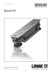
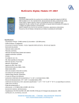
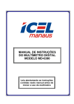
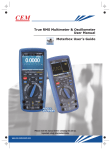
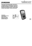
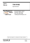
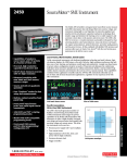
PXI7052
User’s Manual
Beijing ART Technology Development Co., Ltd.
PXI7052 Digital Multimeter
V6.022
Contents
Contents ................................................................................................................................................................................2
Chapter 1 Overview ..............................................................................................................................................................3
Chapter 2 Component Layout Diagram and a Brief Description .........................................................................................4
2.1 The Main Component Layout Diagram ..................................................................................................................4
2.2 The Function Description for the Main Component ...............................................................................................4
2.2.1 Signal Input and Output Connectors ............................................................................................................4
2.2.2 Physical ID of DIP Switch ...........................................................................................................................4
Chapter 3 Operation Method ................................................................................................................................................6
3.1 Voltage (AC V) Measurement.................................................................................................................................6
3.2 Voltage (DC mV) Measurement..............................................................................................................................6
3.3 Voltage (DC V) Measurement.................................................................................................................................7
3.4 Logic Frequency/Duty Cycle Measurement ...........................................................................................................7
3.5 Diode Measurement (Diode VF).............................................................................................................................7
3.6 Capacitance Measurement ......................................................................................................................................8
3.7 Resistance/ON-OFF Measurement .........................................................................................................................8
3.8 Current (A) Measurement .......................................................................................................................................9
3.9 Current (mA) Measurement ....................................................................................................................................9
3.10 Current (µA) Measurement...................................................................................................................................9
3.11 The Range Addition/Subtraction Selection .........................................................................................................10
3.11.1 Range Addition.........................................................................................................................................10
3.11.2 Range Subtraction ....................................................................................................................................10
3.12 Calibration...........................................................................................................................................................10
3.12.1 Zero-point Calibration..............................................................................................................................11
3.12.2 Full-scale Calibration ...............................................................................................................................11
Chapter4 Range and Accuracy ...........................................................................................................................................12
4.1 DC Measurement ..................................................................................................................................................12
4.2 AC Measurement...................................................................................................................................................12
4.3 Other Measurement...............................................................................................................................................13
Chapter5 Notes, Calibration and Warranty Policy.............................................................................................................14
5.1 Notes .....................................................................................................................................................................14
5.2 Fault Diagnosis .....................................................................................................................................................14
5.3 Warranty Policy.....................................................................................................................................................14
Products Rapid Installation and Self-check ........................................................................................................................15
Rapid Installation ........................................................................................................................................................15
Self-check ...................................................................................................................................................................15
Delete Wrong Installation ...........................................................................................................................................15
BUY ONWIRE at art-control.com/englishs or CALL +86-010-62991792-609(CN)
2
PXI7052 Digital Multimeter
V6.022
Chapter 1 Overview
Unpacking Checklist
Check the shipping carton for any damage. If the shipping carton and contents are damaged, notify the local dealer or
sales for a replacement. Retain the shipping carton and packing material for inspection by the dealer.
Check for the following items in the package. If there are any missing items, contact your local dealer or sales.
¾ PXI7052 Card
¾ ART Disk
a) user’s manual (pdf)
b) drive
c) catalog
¾ Warranty Card
PARAMETER
¾
¾
¾
¾
¾
¾
¾
¾
¾
¾
¾
¾
¾
¾
¾
¾
5000 counting measurement, max. display: 4999, that is 44/5 digits
Auto/manual range, the basic sample rate is 2.5 times/sec.
Measurement Type: AC voltage, DC voltage, current, resistance, capacitance, diode, frequency
Measuring range: AC voltage: 5V, 50V, 500V, 1000V
DC voltage: 50mV, 500mV, 5V, 50V, 500V, 1000V
Current: 500μA, 5000μA, 50mA, 500mA, 5A, 10A
Resistance: 500Ω, 5KΩ, 50KΩ, 500KΩ, 5MΩ, 50MΩ
Capacitance: 500nF, 5μF, 50μF, 500μF
ACV and DCV measurements up to 1000V
AC true RMS measurement
DC measurement accuracy is 0.03%
0.01Ω resistance resolution and the 1μV voltage resolution
In the μA/mA measurement, the protection current is 0.64A
Capacitance measurement from 0.01nF to 500μF
Wirear frequency measurement, logic frequency/duty cycle measurement
Over-range indicator OL
Fuse 0.63A/500V (μA/mA side), 10A/500V (10A side)
The max voltage between the measurement side and the earth is 1000V AC/DC. 1000V CAT II, pollution degree 2
Operating Temperature: 5℃~ 30℃ (relative humidity 0~80%)
31℃~ 41℃ (relative humidity 0~50%)
Storage Temperature -20℃~ 60℃ (relative humidity ≤ 80%)
FEATURES
¾
¾
¾
¾
Auto/manual range selection
Computer display, record
Overload protection
Measurement signal digital isolation
BUY ONWIRE at art-control.com/englishs or CALL +86-010-62991792-609(CN)
3
PXI7052 Digital Multimeter
V6.022
Chapter 2 Component Layout Diagram and a Brief Description
2.1 The Main Component Layout Diagram
2.2 The Function Description for the Main Component
2.2.1 Signal Input and Output Connectors
V/Ω/F/Hz: except the current measurement, all the other measurements use it as the input port, connect with the red
multimeter pen.
COM: the negative input of the all measurements, connect with the black multimeter pen.
μA / mA: it is the positive input when measuring current μA, mA, connect with the red multimeter pen.
10A: it is the positive input when measuring current 0.5A~10A, connect with the red multimeter pen.
2.2.2 Physical ID of DIP Switch
DID1: Set physical ID number. When the PC is installed more than one PXI8191, you can use the DIP switch to set a
physical ID number for each board, which makes it very convenient for users to distinguish and visit each board in the
progress of the hardware configuration and software programming. The following four-bit number is expressed by the
binary system: When DIP switch points to "ON", that means "1", and when it points to the other side, that means "0." As
they are shown in the following diagrams: "ID3" is the high bit."ID0" is the low bit, and the black part in the diagram
represents the location of the switch. (Test software of the company often uses the logic ID management equipments and
at this moment the physical ID DIP switch is invalid. If you want to use more than one kind of the equipments in one and
the same system at the same time, please use the physical ID as much as possible).
BUY ONWIRE at art-control.com/englishs or CALL +86-010-62991792-609(CN)
4
PXI7052 Digital Multimeter
V6.022
ID3 ID2 ID1 ID0
4
3
2
1
DID1
ON
ON
The above chart shows"1111", so it means that the physical ID is 15.
ID3 ID2 ID1 ID0
4
3
2
1
DID1
ON
ON
The above chart shows"0111", so it means that the physical ID is 7.
ID3 ID2 ID1 ID0
4
3
2
1
DID1
ON
ON
The above chart shows"0101", so it means that the physical ID is 5.
ID3
OFF(0)
ID2
OFF(0)
ID1
OFF(0)
ID0
Physical ID (Hex)
Physical ID(Dec)
OFF(0)
0
0
OFF(0)
OFF(0)
OFF(0)
ON(1)
1
1
OFF(0)
OFF(0)
ON(1)
OFF(0)
2
2
OFF(0)
OFF(0)
ON(1)
3
3
OFF(0)
OFF(0)
4
4
OFF(0)
ON(1)
ON(1)
ON(1)
OFF(0)
5
ON(1)
ON(1)
OFF(0)
5
OFF(0)
OFF(0)
ON(1)
6
6
OFF(0)
ON(1)
ON(1)
7
7
ON(1)
OFF(0)
OFF(0)
ON(1)
OFF(0)
8
8
ON(1)
OFF(0)
OFF(0)
9
9
ON(1)
OFF(0)
ON(1)
A
10
ON(1)
OFF(0)
ON(1)
B
11
ON(1)
ON(1)
OFF(0)
ON(1)
OFF(0)
C
12
ON(1)
ON(1)
OFF(0)
D
13
ON(1)
ON(1)
ON(1)
ON(1)
OFF(0)
E
14
ON(1)
ON(1)
ON(1)
ON(1)
F
15
ON(1)
OFF(0)
BUY ONWIRE at art-control.com/englishs or CALL +86-010-62991792-609(CN)
5
PXI7052 Digital Multimeter
V6.022
Chapter 3 Operation Method
Measurement software interface is shown as below, the following details are about the operation of the measurement
method.
3.1 Voltage (AC V) Measurement
Measurement the voltage range AC 0.5V~1000V. Measurement method is as follows:
1, open the program, press the "AC V" button.
2, connect one side of the red test wire to V/Ω/F/Hz side, and one side of the black test wire to the COM terminal.
3, before to measure, connect the other side of the red and black test wire to the both ends of the voltage that is
measured.
4, when measurement, the "Manual" button is Manual selection range, we can manually select the range in the range
selection box. And we also can press the "Manual" button to switch to the "Auto", automatically select range, the
display box will show "AUTO", then the measurement range will be automatically selected based on the size of the
measured signal.
5, read the measurement value from the display box. If display "OL", means the measurement voltage is over the
instrument's range, the red and black test wire should be disconnected from the test circuit immediately.
Note: The measurement voltage should be not over 1000V.
3.2 Voltage (DC mV) Measurement
Measurement the voltage range DC 1μV~500mV. Measurement method is as follows:
1, open the program, press the "DC mV" button.
2, connect one side of the red test wire to V/Ω/F/Hz side, and one side of the black test wire to the COM terminal.
BUY ONWIRE at art-control.com/englishs or CALL +86-010-62991792-609(CN)
6
PXI7052 Digital Multimeter
V6.022
3, before to measure, connect the other side of the red test wire with the positive side of the measured voltage signal
and the black test wire to the negative side of the measured voltage signal.
4, when measurement, the "Manual" button is Manual selection range, we can manually select the range in the range
selection box. And we also can press the "Manual" button to switch to the "Auto", automatically select range, the
display box will show "AUTO", then the measurement range will be automatically selected based on the size of the
measured signal.
5, read the measurement value from the display box. If display "OL", means the measurement voltage is over the
instrument's range, the red and black test wire should be disconnected from the test circuit immediately.
Note: when the test wire is floating, there may be display a stable reading caused by the the sense voltage in the test wire,
but does not affect the measurement accuracy.
3.3 Voltage (DC V) Measurement
Measurement the voltage range DC 0.5V~1000V. Measurement method is as follows:
1, open the program, press the "DC V" button.
2, connect one side of the red test wire to V/Ω/F/Hz side, and one side of the black test wire to the COM terminal.
3, before to measure, connect the other side of the red test wire with the positive side of the measured voltage signal
and the black test wire to the negative side of the measured voltage signal.
4, when measurement, the "Manual" button is Manual selection range, we can manually select the range in the range
selection box. And we also can press the "Manual" button to switch to the "Auto", automatically select range, the
display box will show "AUTO", then the measurement range will be automatically selected based on the size of the
measured signal.
5, read the measurement value from the display box. If display "OL", means the measurement voltage is over the
instrument's range, the red and black test wire should be disconnected from the test circuit immediately.
Note: The measurement voltage should be not over 1000V.
3.4 Logic Frequency/Duty Cycle Measurement
Frequency range is 10Hz~1MHz (Vp 2.5~5V), duty cycle range is 10% ~ 90%. Measurement method is as follows:
1, open the program, press the "Hz" button.
2, connect one side of the red test wire to V/Ω/F/Hz side, and one side of the black test wire to the COM terminal.
3, connect the red test wire with the logic high-level and the black test wire to the logic low-level.
4, the measured value read from the display.
5, this item is automatic range, "Manual"/"Auto" button is invalid.
Note: the signal frequency is lower or higher than the measuring range of the instrument, the reading value maybe not
correct.
3.5 Diode Measurement (Diode VF)
The forward voltage drop of the diode is 0~2.5V. Measurement method is as follows:
1, open the program, press the "Diode VF" button.
2, connect one side of the red test wire to V/Ω/F/Hz side, and one side of the black test wire to the COM terminal.
3, connect the red test wire with the anode of the diode, the black test wire to the cathode of the diode, the display will
show the forward voltage drop of the diode.
4, connect the black test wire with the anode of the diode, the red test wire to the cathode of the diode, if the display
shows “OL”, it means the reverse resistance is normal, otherwise, it means diode reverse leakage.
BUY ONWIRE at art-control.com/englishs or CALL +86-010-62991792-609(CN)
7
PXI7052 Digital Multimeter
V6.022
Note: If test the diode in the circuit board, we should power off and then measure. Because there may be other parallel
circuit, the test value maybe not listed as the 3, 4 above.
3.6 Capacitance Measurement
Capacitance measurement range is 100nF~500μF. Measurement method is as follows:
1, open the program, press the "CAP" button.
2, connect one side of the red test wire to V/Ω/F/Hz side, and one side of the black test wire to the COM terminal.
3, if the capacitance has voltage, shorted the capacitance to discharge.
4, connect the red and black test wire to the capacitance, if the capacitance is polarity, the red test wire should connect
with the anode, the black test wire connect with the cathode.
5, when measurement, the "Manual" button is Manual selection range, we can manually select the range in the range
selection box. And we also can press the "Manual" button to switch to the "Auto", automatically select range, the
display box will show "AUTO", then the measurement range will be automatically selected based on the size of the
measured signal.
6, read the capacitance value from the display. If the capacitance value> 500μF, meter will display OL. If the capacitance
<10nF, will display 0.
Note: when measure 50μF ~ 500μF capacitance, in order to ensure the measurement accuracy, the instrument will take a
long time to discharge for the capacitance, so the measurement value is refreshed slowly.
Do not measure the capacitance on the circuit that has other components in parallel, because it will cause large
error.
3.7 Resistance/ON-OFF Measurement
Resistance measurement range is 0.1Ω ~ 50MΩ. Measurement method is as follows:
1, open the program, press the "Res/Short" button.
2, connect one side of the red test wire to V/Ω/F/Hz side, and one side of the black test wire to the COM terminal.
3, click the "Res/Short" button to select "Resistance", the resistance measurement mode, and the "Short" is ON-OFF
mode.
4, when measurement, the "Manual" button is Manual selection range, we can manually select the range in the range
selection box. And we also can press the "Manual" button to switch to the "Auto", automatically select range, the
display box will show "AUTO", then the measurement range will be automatically selected based on the size of the
measured signal.
5, for the resistance measurement, connect the red and black test wires with the resistance, read the measurement value
from the display box. In “Manual” mode, if it displays "OL", it means over the range and we should select the greater
range to measure. If it displays "OL" in the maximum range, it means the resistance is greater than 50MΩ.
For ON-OFF measurement, connect the red and black test wires with the two measurement points, if the resistance
between two points is less than 50Ω ~ 60Ω, the buzzer will sound, and the display box shows the resistance value, if
display "OL", it means the resistance is greater than 500Ω.
Note: If test the ON-OFF in the circuit board, we should power off and then measure. Because there may be other
parallel circuit, the test value maybe not the real value of the resistance.
BUY ONWIRE at art-control.com/englishs or CALL +86-010-62991792-609(CN)
8
PXI7052 Digital Multimeter
V6.022
3.8 Current (A) Measurement
Current measurement range is DC 0.1mA ~ 10A, AC 0.5A ~ 10A. Measurement method is as follows:
1, open the program, press the "A" button.
2, connect one side of the red test wire to10A side, and one side of the black test wire to the COM terminal.
3, click the "A" button to select "DC Current" for the DC measurement mode, or select "AC Current" for the AC
measurement mode.
4, when measurement, the "Manual" button is Manual selection range, we can manually select the range in the range
selection box. And we also can press the "Manual" button to switch to the "Auto", automatically select range, the
display box will show "AUTO", in this mode, Range selection box is invalid.
5, turn off the power of the circuit, access the red and black test wire to the test circuit in series mode, and then turn on
the power of the test circuit under.
6, read the measurement value the from the display box. In DC mode, if it displays positive, means the current is from
the red test wire to the instrument. If it displays negative, means the current is from the black test wire to the
instrument. If display "OL", means the current over-range.
Note: pre-estimated the measurement current, and the A table should be not over fuse current value (0.63A).
3.9 Current (mA) Measurement
Current measurement range is DC 1µA~500mA,AC 5mA~500mA. Measurement method is as follows:
1, open the program, press the "mA" button.
2, connect one side of the red test wire to µA/mA side, and one side of the black test wire to the COM terminal.
3, click the "A" button to select "DC Current" for the DC measurement mode, or select "AC Current" for the AC
measurement mode.
4, when measurement, the "Manual" button is Manual selection range, we can manually select the range in the range
selection box. And we also can press the "Manual" button to switch to the "Auto", automatically select range, the
display box will show "AUTO", in this mode, Range selection box is invalid.
5, turn off the power of the circuit, access the red and black test wire to the test circuit in series mode, and then turn on
the power of the test circuit under.
6, read the measurement value the from the display box. In DC mode, if it displays positive, means the current is from
the red test wire to the instrument. If it displays negative, means the current is from the black test wire to the
instrument. If display "OL", means the current over-range.
Note: pre-estimated the measurement current, and the A table should be not over fuse current value (0.63A).
3.10 Current (µA) Measurement
Current measurement range is DC 0.01µA~5000µA,AC 5µA~5000µA. Measurement method is as follows:
1, open the program, press the "µA" button.
2, connect one side of the red test wire to µA/mA side, and one side of the black test wire to the COM terminal.
3, click the "A" button to select "DC Current" for the DC measurement mode, or select "AC Current" for the AC
measurement mode.
4, when measurement, the "Manual" button is Manual selection range, we can manually select the range in the range
selection box. And we also can press the "Manual" button to switch to the "Auto", automatically select range, the
display box will show "AUTO", in this mode, Range selection box is invalid.
BUY ONWIRE at art-control.com/englishs or CALL +86-010-62991792-609(CN)
9
PXI7052 Digital Multimeter
V6.022
5, turn off the power of the circuit, access the red and black test wire to the test circuit in series mode, and then turn on
the power of the test circuit under.
6, read the measurement value the from the display box. In DC mode, if it displays positive, means the current is from
the red test wire to the instrument. If it displays negative, means the current is from the black test wire to the
instrument. If display "OL", means the current over-range.
Note: pre-estimated the measurement current, and the A table should be not over fuse current value (0.63A).
3.11 The Range Addition/Subtraction Selection
For various measurements, there are two shortcut keys: "Range +1" and "Range-1" corresponding to range
addition and subtraction.
3.11.1 Range Addition
When select a range measurement, it displays "OL", means the measurement value is over the setting range, should
choose a greater range to measure, this time, click on "Range +1" to select the greater range.
However, if it displays "OL" in the maximum range, click "Range +1" button to return to select the smallest range.
3.11.2 Range Subtraction
When select a measurement range, click the "Range-1" button to select a small range by descending.
However, if in the minimum range to click the "Range +1" button, it will return to select the maximum range.
3.12 Calibration
The card has been calibrated before leave the factory, only after use a period of time, it needs to be calibrated. In the
calibration, we should use the multimeter and signal source that the accuracy is higher than the card.
The function that can be calibrated shown as the follwoing: voltage (AC), current (AC) (use 10KHz AC signal source for
calibration--default), DC mV, V, DC μA, DC mA, DC A, and the resistance.
Click the "Adjust" button, the calibration dialog box will pop up, then we can do zero-point calibration, full-scale
calibration, and clear the calibration value.
BUY ONWIRE at art-control.com/englishs or CALL +86-010-62991792-609(CN)
10
PXI7052 Digital Multimeter
V6.022
3.12.1 Zero-point Calibration
Connect the red and black test wire of the card, short the red and black table, click on the "zero calibration" button,
then wait for the screen to prompt the zero-point calibration is completed, advanced program will record zero code value.
If not shorted the table, it will pop-up dialog box "Please confirm whether connect the positive and negative port of the
table", then connected the table to complete the zero-point calibration.
3.12.2 Full-scale Calibration
Only after the zero-point calibration, we can do the full-scale calibration. Access the signal source that is about the
full-range of the PXI7052 to the PXI7052 card, use the multimeter which accuracy is higher than the PXI7052 to
measure the true value, then write the actual measurement value into the " actual measurement value" dialog box, last
click "full-scale calibration" button to complete the full-scale calibration. Click "OK" to exit calibration.
Special Note: the AC signal only need to do full-scale calibration.
Operation Method: after the zero-point calibration, click "Clear calibration value" button, then wire the actual standard
measurement value to “actual measurement value" dialog, last click the "full-scale calibration" to complete the
full-scale calibration.
BUY ONWIRE at art-control.com/englishs or CALL +86-010-62991792-609(CN)
11
PXI7052 Digital Multimeter
V6.022
Chapter4 Range and Accuracy
Following range is the instrument calibrated within one year, under normal use, the basic conditions for the working
temperature is 18℃~ 28℃, relative humidity less than 80%. The accuracy is: ± (% of reading ** + low number).
4.1 DC Measurement
Voltage DC
Range
Resolution
Accuracy
50mV
0.001mV
±(0.05% + 15)
500mV
0.01mV
±(0.05% + 10)
5V
0.1mV
±(0.05% + 10)
50V
1mV
±(0.05% + 10)
500V
10mV
±(0.05% + 10)
1000V
0.1V
±(0.05% + 10)
Note: The above accuracy can be guaranteed within the all ranges.
Current DC
Range
Resolution
Accuracy
Voltage Drop
500µA
0.01µA
±(0.25% + 15)
5000µA
0.1µA
±(0.25% +10)
50mA
1µA
±(0.25% + 10)
500mA
10µA
±(0.25% + 10)
5A
0.1mA
±(0.5% + 10)
10A
1mA
±(0.5% + 10)
102µV/µA
1.5mV/mA
30mV/A
Note: The above accuracy can be guaranteed within the all ranges.
4.2 AC Measurement
Voltage AC
Accuracy
Range
Resolution
5V
0.1mV
20Hz~1KHz
±(2.5% + 40)
50V
1mV
±(2.5% + 40)
500V
10mV
1000V
0.1V
1KHz~10KHz
10KHz~20KHz
±(1% + 40)
±(2.5% + 40)
±(2.5% + 40)
±(2.5% + 40)
±(1% + 40)
reserved
±(2.5% + 40)
reserved
reserved
reserved
Note: The above accuracy can be guaranteed within the 10% ~100% of the full range.
Current AC
Range
Resolution
500µA
0.01µA
5000µA
50mA
Accuracy
20Hz~100Hz
100Hz~500Hz
500Hz~1KHz
±(0.75% + 20)
±(2% + 20)
0.1µA
±(2% + 20)
±(2% + 10)
±(0.75% + 10)
±(2 % + 10)
1µA
±(2% + 20)
±(0.75% + 20)
±(2% + 20)
Voltage
Drop
102µV/µA
1.5mV/mA
BUY ONWIRE at art-control.com/englishs or CALL +86-010-62991792-609(CN)
12
PXI7052 Digital Multimeter
V6.022
500mA
10µA
±(2% + 10)
±(0.1% + 10)
±(2% + 10)
5A
0.1mA
±(2% + 20)
±(0.75% + 20)
±(2% + 20)
30mV/A
Note: The above accuracy can be guaranteed within the 10% ~100% of the full range.
4.3 Other Measurement
Resistance
Range
Resolution
Accuracy
500Ω
0.01Ω
±(0.5% + 10)
5KΩ
0. 1Ω
±(0.5% + 5)
50KΩ
1Ω
±(0.5% +5)
500KΩ
10Ω
±(0.5% + 5)
5MΩ
100Ω
±(0.5% + 10)
50MΩ
1KΩ
±(1% + 10)
Note: The above accuracy can be guaranteed within the all ranges.
Capacitance
Range
Resolution
Accuracy
500nF
0. 1nF
±(1% + 15)
5µF
1nF
±(1% + 10)
50µF
10nF
±(1% + 10)
500µF
0.1µF
±(10% + 10)
Range
Resolution
Accuracy
2.5V
0.1mV
±(1% + 5)
Diode
Note: The test current is about 0.7mA.
Logical Frequency
Frequency Range
10Hz~1MHz
Input Range
Vp 2~5VSquare wave
Resolution
Accuracy
2Hz
±(0.06% + 4)
Duty Cycle
Frequency Range
10Hz~500KHz
Duty Cycle Range
10%~90%
Resolution
Accuracy
0.01%
±(0.06% + 4)
BUY ONWIRE at art-control.com/englishs or CALL +86-010-62991792-609(CN)
13
PXI7052 Digital Multimeter
V6.022
Chapter5 Notes, Calibration and Warranty Policy
5.1 Notes
In our products’ packing, user can find a user manual, a PXI7052 module and a quality guarantee card. Users must keep
quality guarantee card carefully, if the products have some problems and need repairing, please send products together
with quality guarantee card to ART, we will provide good after-sale service and solve the problem as quickly as we can.
When using PXI7052, in order to prevent the IC (chip) from electrostatic harm, please do not touch IC (chip) in the
front panel of PXI7052 module.
5.2 Fault Diagnosis
1. If the multimeter card does not read, we can press the "Ctrl + R" of the keyboard to reset the chip of the multimeter.
2. If the measured value is higher than the selection range, it will display "OL", please select the right range.
5.3 Warranty Policy
Thank you for choosing ART. To understand your rights and enjoy all the after-sales services we offer, please read the
following carefully.
1. Before using ART’s products please read the user manual and follow the instructions exactly. When sending in
damaged products for repair, please attach an RMA application form which can be downloaded from:
www.art-control.com.
2. All ART products come with a limited two-year warranty:
¾ The warranty period starts on the day the product is shipped from ART’s factory
¾ For products containing storage devices (hard drives, flash cards, etc.), please back up your data before sending
them for repair. ART is not responsible for any loss of data.
¾ Please ensure the use of properly licensed software with our systems. ART does not condone the use of pirated
software and will not service systems using such software. ART will not be held legally responsible for products
shipped with unlicensed software installed by the user.
3. Our repair service is not covered by ART's guarantee in the following situations:
¾ Damage caused by not following instructions in the User's Manual.
¾ Damage caused by carelessness on the user's part during product transportation.
¾ Damage caused by unsuitable storage environments (i.e. high temperatures, high humidity, or volatile chemicals).
¾ Damage from improper repair by unauthorized ART technicians.
¾ Products with altered and/or damaged serial numbers are not entitled to our service.
4. Customers are responsible for shipping costs to transport damaged products to our company or sales office.
5. To ensure the speed and quality of product repair, please download an RMA application form from our company
website.
BUY ONWIRE at art-control.com/englishs or CALL +86-010-62991792-609(CN)
14
PXI7052 Digital Multimeter
V6.022
Products Rapid Installation and Self-check
Rapid Installation
Product-driven procedure is the operating system adaptive installation mode. After inserting the disc, you can select the
appropriate board type on the pop-up interface, click the button【driver installation】or select CD-ROM drive in Resource
Explorer, locate the product catalog and enter into the APP folder, and implement Setup.exe file. After the installation,
pop-up CD-ROM, shut off your computer, insert the PCI card. If it is a USB product, it can be directly inserted into the
device. When the system prompts that it finds a new hardware, you do not specify a drive path, the operating system can
automatically look up it from the system directory, and then you can complete the installation.
Self-check
At this moment, there should be installation information of the installed device in the Device Manager (when the device
does not work, you can check this item.). Open "Start -> Programs -> ART Demonstration Monitoring and Control
System -> Corresponding Board -> Advanced Testing Presentation System", the program is a standard testing procedure.
Based on the specification of Pin definition, connect the signal acquisition data and test whether AD is normal or not.
Connect the input pins to the corresponding output pins and use the testing procedure to test whether the switch is
normal or not.
Delete Wrong Installation
When you select the wrong drive, or viruses lead to driver error, you can carry out the following operations: In Resource
Explorer, open CD-ROM drive, run Others-> SUPPORT-> PCI.bat procedures, and delete the hardware information that
relevant to our boards, and then carry out the process of section I all over again, we can complete the new installation.
BUY ONWIRE at art-control.com/englishs or CALL +86-010-62991792-609(CN)
15