1
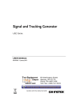
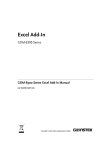
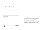
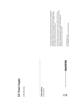
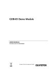
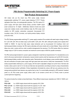
Digital Storage Oscilloscope GDS-3000 Series SERIAL DECODE MANUAL GW INSTEK PART NO. ISO-9001 CERTIFIED MANUFACTURER This manual contains proprietary information, which is protected by copyright. All rights are reserved. No part of this manual may be photocopied, reproduced or translated to another language without prior written consent of Good Will company. The information in this manual was correct at the time of printing. However, Good Will continues to improve products and reserves the rights to change specification, equipment, and maintenance procedures at any time without notice. Good Will Instrument Co., Ltd. No. 7-1, Jhongsing Rd., Tucheng City, Taipei County 236, Taiwan. TABLE OF CONTENTS Table of Contents SAFETY INSTRUCTIONS ................................................... 5 GETTING STARTED ........................................................... 9 Activating Optional Software ............... 10 QUICK REFERENCE ......................................................... 12 Menu Tree / Operation Shortcuts ........ 13 MEASUREMENT .............................................................. 16 Serial Bus ............................................ 17 INDEX............................................................................. 27 3 4 SAFETY INSTRUCTIONS SAFETY INSTRUCTIONS This chapter contains important safety instructions that you must follow during operation and storage. Read the following before any operation to insure your safety and to keep the instrument in the best possible condition. Safety Symbols These safety symbols may appear in this manual or on the GDS3000. WARNING Warning: Identifies conditions or practices that could result in injury or loss of life. CAUTION Caution: Identifies conditions or practices that could result in damage to the GDS-3000 or to other properties. DANGER High Voltage Attention Refer to the Manual Protective Conductor Terminal Earth (ground) Terminal 5 GDS-3000 Serial Decode User Manual Do not dispose electronic equipment as unsorted municipal waste. Please use a separate collection facility or contact the supplier from which this instrument was purchased. Safety Guidelines General Guideline CAUTION 6 Make sure the BNC input voltage does not exceed 300V peak. Never connect a hazardous live voltage to the ground side of the BNC connectors. It might lead to fire and electric shock. Do not place any heavy object on the GDS-3000. Avoid severe impact or rough handling that leads to damaging the GDS-3000. Do not discharge static electricity to the GDS3000. Use only mating connectors, not bare wires, for the terminals. Do not block the cooling fan opening. Do not perform measurement at a power source or building installation site (Note below). Do not disassemble the GDS-3000 unless you are qualified. Ensure a proper ground is used at all times with the instrument. SAFETY INSTRUCTIONS (Measurement categories) EN 61010-1:2001 specifies the measurement categories and their requirements as follows. the GDS-3000 falls under category II. Measurement category IV is for measurement performed at the source of low-voltage installation. Measurement category III is for measurement performed in the building installation. Measurement category II is for measurement performed on the circuits directly connected to the low voltage installation. Measurement category I is for measurements performed on circuits not directly connected to Mains. Power Supply WARNING Cleaning the GDS-3000 Operation Environment AC Input voltage: 100 ~ 240V AC, 48 ~ 63Hz, auto selection Connect the protective grounding conductor of the AC power cord to an earth ground, to avoid electrical shock. Disconnect the power cord before cleaning. Use a soft cloth dampened in a solution of mild detergent and water. Do not spray any liquid. Do not use chemical containing harsh material such as benzene, toluene, xylene, and acetone. Location: Indoor, no direct sunlight, dust free, almost non-conductive pollution (Note below) Relative Humidity: < 80% Altitude: < 2000m Temperature: 0°C to 50°C 7 GDS-3000 Serial Decode User Manual (Pollution Degree) EN 61010-1:2001 specifies the pollution degrees and their requirements as follows. The GDS-3000 falls under degree 2. Pollution refers to “addition of foreign matter, solid, liquid, or gaseous (ionized gases), that may produce a reduction of dielectric strength or surface resistivity”. Pollution degree 1: No pollution or only dry, non-conductive pollution occurs. The pollution has no influence. Pollution degree 2: Normally only non-conductive pollution occurs. Occasionally, however, a temporary conductivity caused by condensation must be expected. Pollution degree 3: Conductive pollution occurs, or dry, nonconductive pollution occurs which becomes conductive due to condensation which is expected. In such conditions, equipment is normally protected against exposure to direct sunlight, precipitation, and full wind pressure, but neither temperature nor humidity is controlled. Storage environment Location: Indoor Temperature: -20°C to 70°C Disposal Do not dispose this instrument as unsorted municipal waste. Please use a separate collection facility or contact the supplier from which this instrument was purchased. Please make sure discarded electrical waste is properly recycled to reduce environmental impact. 8 GETTING STARTED GETTING STARTED This chapter describes how to install the serial decode software or trial demonstration. Activating Optional Software ........................................... 10 9 GDS-3000 Serial Decode User Manual Activating Optional Software Background The GDS-3000 has Power Analysis software and Serial bus decoding software (17) as optional extras. An activation key is required to activate the software. An activation key is required for each optional software package. If the serial decode software has not been purchased, a time trial demonstration is available for a 1 month period. Before activating the time trial demonstration, ensure the date and time has been set. Changing the system date will not have an effect on the time trial period. The time trial demonstration software can only be used once. For the latest files and information regarding the optional software packages, see the GW Instek website: www.gwinstek.com BusEnableTrial.LIS BusEnable.LIS Activation key filenames Serial bus decode activation keys Steps 1. Ensure the date and time has been See the user manual for set. details. 2. Insert a USB stick into front panel USB port with the activation keys located in the root directory. 3. Press the Utility key. 10 GETTING STARTED 4. Press File Utilities from the bottom menu. 5. The file system appears. 6. Use the Variable knob and Select key to select the activation key from the USB root directory. When prompted to continue, press the Select key again. Files: BusEnableTrial.LIS BusEnable.LIS Confirm Activation key Press B1 on the front panel to see if the Serial Bus decode activation worked. 11 GDS-3000 Serial Decode User Manual QUICK REFERENCE This chapter depicts the power analysis menu tree. Use them as a handy reference to get quick access to the functionality. Menu Tree / Operation Shortcuts .................................... 13 BUS – I2C ............................................................................. 13 BUS – SPI ............................................................................. 14 BUS – UART........................................................................ 15 12 QUICK REFERENCE Menu Tree / Operation Shortcuts BUS – I2C 13 GDS-3000 Serial Decode User Manual BUS – SPI 14 QUICK REFERENCE BUS – UART 15 GDS-3000 Serial Decode User Manual MEASUREMENT Serial Bus ........................................................................ 17 Serial Bus Overview ............................................................. 17 UART Serial Bus Interface ................................................. 19 I2C Serial Bus Interface ...................................................... 22 SPI Serial Bus Interface ....................................................... 24 16 MEASUREMENT Serial Bus The serial bus trigger and decode software includes support for 3 common serial interfaces, SPI, UART and 12C. Each interface is fully configurable to accommodate a wide range of protocol variation. Up to two different UART or I2C buses can be used at the same time. Only 1 SPI bus can be used at a time. Each input can be displayed as binary or hexadecimal. An event table can also be created to aid in debugging. Note that the Serial bus trigger and decode software is an optional extra. An activation key is required to activate the software. A month trial demonstration is also available. For details please see page 10. Serial Bus Overview UART Universal Asynchronous Receiver Transmitter. The UART bus is able to accommodate a wide range of various common UART serial communications. The UART serial bus software is suitable for a number of RS-232 protocol variants. Inputs Tx, Rx, Polarity Threshold Tx, Rx (±10V) Configuration Baud Rate, Data Bits, Parity, Packets I2C Inter Integrated circuit is a two line serial data interface with a serial data line (SDA) and serial clock line (SCL). The R/W bit can be configured. Inputs SCLK, SDA Threshold SCLK, SDA (±10V) Configuration Read, Write in address 17 GDS-3000 Serial Decode User Manual SPI The SPI (Serial Interface Peripheral) bus is fully configurable to accommodate the wide variety of SPI interfaces. Inputs SCLK, SS, MOSI, MISO Threshold SCLK, SS, MOSI, MISO (±10V) Configuration SCLK edge, SS logic level, MOSI logic level, MISO logic level, word size, bit order 18 MEASUREMENT UART Serial Bus Interface The UART serial bus software is designed to decode RS232 and other common RS-232 variants such as RS-422, RS-485. The software configuration is also flexible enough to decode the many proprietary protocols based on RS-232. Background Basic RS-232 protocol uses single-ended data transmissions. The signal voltage levels can be high (±15V) and employ active low signaling. High speed variants of RS-232, such as RS-422 and RS-485 use differential signaling and commonly employ low voltage differential signals with active high signaling. Universal Asynchronous Receiver / Transmitter (UART) or RS-232 driver/receiver ICs commonly used for embedded applications typically use active high signaling with standard IC signal levels. Panel operation 7. Insert each of the bus signals (Tx, Rx) to one of the oscilloscope channels. 8. Press the corresponding bus key, B1 or B2. 9. Press Bus from the bottom menu and choose the UART serial bus on the side menu. 19 GDS-3000 Serial Decode User Manual Define Inputs 10. Press Define Inputs from the bottom menu. 11. From the side menu choose the Tx Input and the Rx Input source and the signal polarity. Tx OFF, CH1~4 Rx OFF, CH1~4 Polarity Normal (High = 0), Inverted (High = 1) Set the Threshold 12. Press Threshold from the bottom menu. 13. Press Select from the side menu. Choose Tx or Rx line thresholds. Range Tx, Rx 14. Press Threshold from the side menu and configure the threshold. Threshold -10V~10V To set to TTL levels (1.4V), press TTL. To set to ECL levels (-1.3V), press ECL. Protocol Configuration 20 The Configure key sets the baud rate, number of data bits and parity. MEASUREMENT 15. Press Configure from the bottom menu. 16. From the side menu select the Baud rate, Data bits, Parity, Packets and End of Packet bits. Baud Rate 50, 75, 110, 134, 150, 300, 600, 1200, 1800, 2000, 2400, 3600, 4800, 7200, 9600, 14400, 15200, 19200, 28800, 31250, 38400, 56000, 57600, 76000, 115200, 128000, 230400, 460800, 921600, 1382400, 1843200, 2764800 Data Bits 7,8,9 Bus Display Parity Odd, Even, None Packets On, Off End of Packet (Hex) 00(NUL), OA(LF), OD(CR), 20(SP), FF Press Bus Display from the bottom menu and Hex or Binary from the side menu. Range Event Table Hex, Binary 17. Press Event Table from the bottom menu. 18. Press Event Table from the side menu to toggle the event table On or Off. Event On, Off 19. To save the event table, press Save Event Table. 21 GDS-3000 Serial Decode User Manual I2C Serial Bus Interface The I2C (I2C) is a single-ended transmission protocol using a serial data line (SDA) and serial clock line (SCL). The decode software will trigger on any of the following conditions: a start/stop condition, a restart, a missing acknowledge message, EEPROM reads, and read/write frames. The I2C trigger can be configured for 7 or 10 bit addressing with the option to ignore the R/W bit. Panel operation 20. Insert each of the bus signals (SCLK, SDA) to one of the oscilloscope channels. 21. Press the corresponding bus key, B1 or B2. 22. Press Bus from the bottom menu and choose I2C from the side menu. Define Inputs 23. Press Define Inputs from the lower menu. 24. From the side menu choose the SCLK input and the SDA Input. SCLK CH1~4 SDA CH1~4 Set the Threshold 25. Press Threshold from the bottom menu. 22 MEASUREMENT 26. From the side menu Press Select to choose SCLK or SDA thresholds. Range SCLK, SDA 27. Press Threshold from the side menu and configure the threshold. Threshold -10V~10V To set to TTL levels (1.4V), press Set to TTL. To set to ECL levels(-1.3V), press Set to ECL. Include R/W in address 28. Press Include R/W in address from the bottom menu. 29. From the side menu select Yes or No. R/W in Address Bus Display Yes, No 30. Press Bus Display from the bottom menu. 31. Choose to display Hex or Binary data on screen. Range Event Table Hex, Binary 32. Pres Event Table from the bottom menu. 23 GDS-3000 Serial Decode User Manual 33. Press Event Table from the side menu to toggle the event table On or Off. Event On, Off 34. To save the event table, press Save Event Table. SPI Serial Bus Interface The serial peripheral interface (SPI) is a full duplex 4 wire synchronous serial interface. The 4 signals lines: Serial clock line (SCLK), slave select (SS), Master output/slave input (MOSI, or SIMO) and the Master input/slave output (MISO, or SOMI). The word size is configurable from 8~32 bits. The SPI triggers on the data pattern at the start of each framing period. Panel operation 35. Insert each of the bus signals (SCLK, SS, MOSI, MISO) to one of the oscilloscope channels. X10 X1 GDS-3354 SCLK X10 X1 SS X10 X1 MOSI X10 X1 MISO 36. Press the corresponding bus key, B1 or B2. 37. Press Bus from the bottom menu and choose the SPI serial bus. Define Inputs 24 38. Press Define Inputs from the lower menu. MEASUREMENT 39. From the side menu choose the SCLK, SS, MOSI and MISO inputs. SCLK CH1~4 SS CH1~4 MOSI OFF, CH1~4 MISO OFF, CH1~4 Set the Threshold 40. Press Threshold from the bottom menu. 41. Press Select from the side menu. Choose SCLK, SS, MOSI or MISO line thresholds. Range SCLK, SS, MOSI, MISO 42. Press Threshold from the side menu and configure the threshold. Threshold -10V~10V To set to TTL levels (1.4V), press Set to TTL. To set to ECL levels (-1.3V), press Set to ECL. Protocol Configuration The Configure menu sets the data line logic level, SCLK edge polarity, word size and bit order. 43. Press Configure from the bottom menu. 44. From the side menu select SCLK edge, SS logic level, MOSI logic level, MISO logic level, word Size and Bit order. 25 GDS-3000 Serial Decode User Manual SCLK rising edge SS Active High, Active Low MOSI Active High, Active Low MISO Active High, Active Low , falling edge Word Size 8 bits, 16 bits, 32 bits Bit Order MS First, LS First Bus Display Press Bus Display from the bottom menu and Hex or Binary from the side menu. Range Event Table Hex, Binary 45. Press Event Table from the bottom menu. 46. Press Event Table from the side menu to toggle the event table On or Off. Event On, Off 47. To save the event table, press Save Event Table. 26 INDEX INDEX Activation keys .......................... 10 Caution symbol ............................ 5 Cleaning the instrument ............. 7 Disposal instructions ................... 8 EN61010 measurement category .................. 7 pollution degree.............................. 8 Environment safety instruction ............................ 7 Ground symbol .............................................. 5 Optional software activation ....................................... 10 Power on/off safety instruction ............................ 7 Serial Bus ..................................... 17 I2C ................................................... 22 overview ........................................ 17 SPI ................................................... 24 UART .............................................. 19 Service operation about disassembly .......................... 6 Software activation .................... 10 Warning symbol ........................... 5 27