1
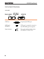
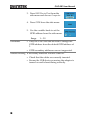
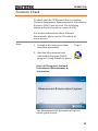
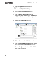
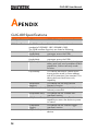
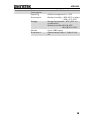
GPIB to USB Adapter GUG-001 USER MANUAL GW INSTEK PART NO. 82UG-00100M01 ISO-9001 CERTIFIED MANUFACTURER This manual contains proprietary information, which is protected by copyright. All rights are reserved. No part of this manual may be photocopied, reproduced or translated to another language without prior written consent of Good Will Corporation. The information in this manual was correct at the time of printing. However, Good Will continues to improve its products and therefore reserves the right to change the specifications, equipment, and maintenance procedures at any time without notice. Windows is a registered trademark of Microsoft Corp., U.S.A. NI-488.2, Measurement and Automation Explorer (MAX) are registered trademarks of National Instruments Corp., U.S.A. Good Will Instrument Co., Ltd. No. 7-1, Jhongsing Rd., Tucheng City, Taipei County 236, Taiwan. SAFETY INSTRUCTIONS Table of Contents SAFETY INSTRUCTIONS .................................. 4 Safety Symbols .......................................................................4 Safety Guidelines....................................................................5 GETTING STARTED.......................................... 7 Main Features .....................................................................7 Instrument Overview ...........................................................8 GUG-001.................................................................................8 OPERATION ..................................................... 9 Set up..................................................................................9 Function Check.................................................................. 11 APENDIX........................................................ 14 GUG-001Specifications ..................................................... 14 3 GUG-001 User Manual SAFETY INSTRUCTIONS This chapter contains important safety instructions that should be followed when using the GPIB to USB adapter. Read the following before any operation to ensure your safety and to keep the adapter in the best condition. Safety Symbols These safety symbols may appear in this manual or on the instrument. WARNING Warning: Identifies conditions or practices that could result in injury or loss of life. CAUTION Caution: Identifies conditions or practices that could result in damage to the instrument or to other objects or property. Attention: Refer to the Manual Protective Conductor Terminal Earth (Ground) Terminal Do not dispose electronic equipment as unsorted municipal waste. Please use a separate collection facility or contact the supplier from which this instrument was purchased. 4 SAFETY INSTRUCTIONS Safety Guidelines General Guideline CAUTION Cleaning the instrument Operation Environment Do not use the adapter in a damp environment or where there is risk of explosion. Do not use the adapter with the case open. The adapter is for indoor use only. Do not place heavy objects on the adapter. Avoid severe impact or rough handling that may damage the adapter. Use only mating connectors, not bare wires, for the interface ports. A soft cloth dampened in a solution of mild detergent and water can be used to clean the case. Do not spray any liquid into the instrument. Do not use chemicals containing harsh products such as benzene, toluene, xylene, and acetone. Location: Indoor, no direct sunlight, dust free, almost non-conductive pollution (Note below) Relative Humidity: ≤ 80%, 40°C or below ≤ 45%, 41°C~50°C Altitude: < 2000m Temperature: 0°C to 50°C 5 GUG-001 User Manual (Pollution Degree) EN 61010-1:2001 specifies pollution degrees and their requirements as follows. The instrument falls under degree 2. Pollution refers to “addition of foreign matter, solid, liquid, or gaseous (ionized gases), that may produce a reduction of dielectric strength or surface resistivity”. Pollution degree 1: No pollution or only dry, non-conductive pollution occurs. The pollution has no influence. Pollution degree 2: Normally only non-conductive pollution occurs. Occasionally, however, a temporary conductivity caused by condensation must be expected. Pollution degree 3: Conductive pollution occurs, or dry, nonconductive pollution occurs which becomes conductive due to condensation which is expected. In such conditions, equipment is normally protected against exposure to direct sunlight, precipitation, and full wind pressure, but neither temperature nor humidity is controlled. Storage environment Location: Indoor Storage Temperature: -10°C~60°C, no condensation- Relative Humidity: 93% @ 40°C 65% @ 41°C ~60°C Disposal 6 Do not dispose this instrument as unsorted municipal waste. Please use a separate collection facility or contact the supplier from which this instrument was purchased. Please make sure discarded electrical waste is properly recycled to reduce environmental impact. GETTING STARTED GETTING STARTED The Getting Started chapter introduces the features, functions and appearance of the GUG001 GPIB to USB adapter. Main Features The GW Instek GPIB to USB adapter is used to connect a GPIB controller to the USB B receptacle on the GDS-3000 as the scope does not have a GPIB interface. The GUG-001 GPIB to USB adapter is currently only supported on the GDS-3000. Features Accessories Enables GPIB control of the GDS-3000 via the USB B receptacle. No power adapter, all power requirements from USB. The GPIB primary address can be assigned via the GDS-3000. User manual, USB type A-B cable. 7 GUG-001 User Manual Instrument Overview GUG-001 GPIB Port 24 pin female GPIB port. USB Type A Receptacle USB type A receptacle connects to the GDS-3000 type B receptacle. Ready Indicator The ready indicator lights when the adapter is ready to use. 8 OPERATION OPERATION GDS-3000 Set Up Procedure 1. Connect a GPIB cable from a GPIB controller to the GPIB port on the adapter. 2. Connect the USB cable from the rear panel device port (type B receptacle) on the oscilloscope to the USB port (type A receptacle) on the GPIB to USB adapter. → 3. The Ready Indicator should be lit after the USB cable is connected. Configure GPIB 1. Press the Utility key on the GDS3000 front panel. 2. Press I/O from the bottom menu. 9 GUG-001 User Manual 3. Press USB Device Port from the side menu and choose Computer. 4. Press GPIB from the side menu. 5. Use the variable knob to set the GPIB address from the side menu. Range Limitations 1 ~ 30 Only the GDS-3000 can be used to change the GPIB address from the default GPIB address of 1. GPIB secondary addresses are not supported. Trouble Shooting If the Ready indicator will not come on: 10 Check that the cables are correctly inserted. Ensure the USB device powering the adapter is turned on and is functioning correctly. OPERATION Function Check To check that the GPIB connection is working, National Instruments Measurement & Automation Explorer (MAX) can be used. The following function check is based on version 4.6.2f1. For further information about National Instruments, please see the NI website at www.ni.com. Steps 1. Complete the setup procedure described previously. Page 9 2. Start the Measurement and Automation Explorer (MAX) program. Using Windows, press; Start>All Programs>National Instruments>Measurement & Automation The Measurement & Automation Explorer initial splash screen. 11 GUG-001 User Manual 3. From the Configuration panel access; My System>Devices and Interfaces>GPIB0(GPIB-USB-B) 4. Press the Scan for Instruments button. 5. In the Connected Instruments panel the oscilloscope should be detected as Instrument 0 with the address the same as that configured on the scope. 6. Double click the Instrument 0 icon. 7. Click on Communicate with Instrument. 8. In the NI-488.2 Communicator window, ensure *IDN? is written in the Send String: text box. Click on the Query button to send the *IDN? query to the oscilloscope. 12 OPERATION 9. The String Received text box will display the query return: GW, GDS-3XXX,PXXXXXX,V1.XX (manufacturer, model, serial number, version) 10. The function check is complete. 13 GUG-001 User Manual APENDIX GUG-001Specifications USB Specification USB Device USB 2.0 full speed device interface GPIB Specification The GPIB interface of this device corresponds to the standard of IEEE488.1-1987, IEEE488.2-1992. The GPIB interface functions are listed as following: SH1(Source This device can transmit multilane Handshake): messages across the GPIB. AH1(Acceptor This device can receive multilane Handshake): messages across the GPIB. T6(Talker): Talker interface function includes basic talker, serial poll, and un-address if MLA capabilities, without talk only mode function. L4(Listener): This device becomes a listener when the controller sends its listen address with ATN (attention) line asserted. This device dose not have listen only capability. SR0(Service This device has no SRQ (Service Request): Request) function. RL0(Remote/Local): This device will ignore the LLO (local lockout) command. PP0(Parallel Poll): This device has no “Parallel Poll” interface function. DC1(Device Clear): This device has “Device Clear” capability to return the device to power on status. DT0(Device This device has no “Device Trigger” Trigger): interface function. C0(Controller): This device can not control other devices. 14 APENDIX Miscellaneous Current Consumption Operating Environment Storage: Altitude Dimensions Less than 0.5 ADC from 5V Ambient temperature: 0 ~ 50°C Relative humidity: ≤ 80%, 40°C or below ≤ 45%, 41°C~50°C Storage Temperature: -10°C~60°C, no condensationRelative humidity: 93% @ 40°C 65% @ 41°C~60°C Up to 2,000 meters Approximately 8.6(L)×7.5(W)×3.3(H) cm 15