1
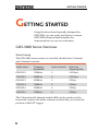
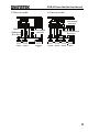
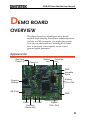
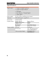
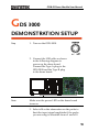
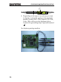
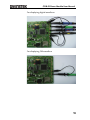
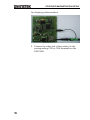
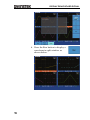
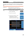
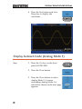
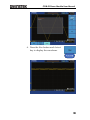
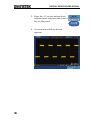
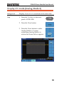
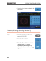
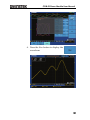
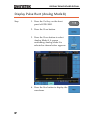
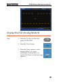
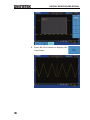
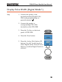
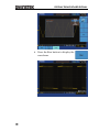
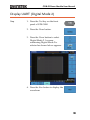
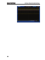
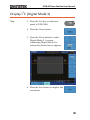
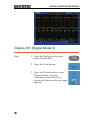
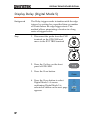
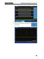
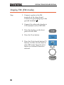
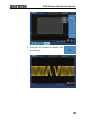
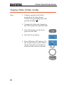
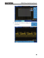
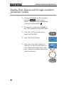
GDB-03 Demo Module
USER MANUAL
GW INSTEK PART NO. 82DB-03000M01
ISO-9001 CERTIFIED MANUFACTURER
This manual contains proprietary information, which is protected by
copyright. All rights are reserved. No part of this manual may be
photocopied, reproduced or translated to another language without
prior written consent of Good Will company.
The information in this manual was correct at the time of printing.
However, Good Will continues to improve products and reserves the
rights to change specification, equipment, and maintenance
procedures at any time without notice.
Good Will Instrument Co., Ltd.
No. 7-1, Jhongsing Rd., Tucheng Dist., New Taipei City 236, Taiwan
GETTING STARTED
Table of Contents
GETTING STARTED ........................................................... 5 GDS-3000 Series Overview ..................... 5 Demonstration type ............................... 7 DEMO BOARD OVERVIEW ................................................ 8 Appearance ............................................ 8 Specification .......................................... 9 GDS 3000 DEMONSTRATION SETUP .............................. 10 DISPLAY DEMO BOARD SIGNAL ..................................... 14 Display VPO (Analog Mode 1) ............. 14 Display Split windows 1
(Analog Mode 2) .................................. 17 Display Split windows 2
(Analog Mode 3) .................................. 18 Display Auto-Range Function
(Analog Mode 4) .................................. 20 Display Autoset mode
(Analog Mode 5) .................................. 21 Display XY mode(Analog Mode 6) ....... 24 Display Gating (Analog Mode 7) .......... 25 Display Pulse Runt (Analog Mode 8) .... 27 Display Rise Fall (Analog Mode 9) ....... 28 Display Pulse Width (Digital Mode 1) .. 30 Display UART (Digital Mode 2) ............ 32 Display I 2 C (Digital Mode 3) ................ 34 Display SPI (Digital Mode 4)................ 35 Display Delay (Digital Mode 5) ............ 37 Display FM (FM mode) ........................ 39 Display Video (Video mode) ................ 41 3
GDB-03 Demo Module User Manual
Display Sine, Square and Triangle waveform
(Generator mode) ................................ 43 4
GETTING STARTED
GETTING STARTED
Using the demo board specially designed for
GDS-3000, you can verify and observe various
GDS-3000 advanced functionalities for
demonstration or your own education.
GDS-3000 Series Overview
Series lineup
The GDS-3000 series consists of 6 models, divided into 2-channel
and 4-channel versions.
Model name
Frequency
bandwidth
Input channels
Real-time
Sampling Rate
GDS-3152
150MHz
2
2.5GSa/s
GDS-3252
250MHz
2
2.5GSa/s
GDS-3352
350MHz
2
5GSa/s
GDS-3154
150MHz
4
5GSa/s
GDS-3254
250MHz
4
5GSa/s
GDS-3354
350MHz
4
5GSa/s
The 2 channel and 4 channel models differ in the position of the
horizontal controls, the math, reference and bus keys as well as the
position of the EXT trigger.
5
GDB-03 Demo Module User Manual
4-Channel model
2-Channel model
Horizontal
controls
Math,
Reference
Bus keys
CH1 CH2
input input
Horizontal
controls
EXT
trigger
Math, Reference
Bus keys
CH1 CH2 CH3 CH4
input input input input
6
GETTING STARTED
Required tools
•
GDS-3000 x 1
•
Demo board x 1
•
USB type A- type B cable x 1. Used for demo board’s power
•
Deep memory: 25k points record length
•
Standard oscilloscope probe x 4
Demonstration type
•
VPO
•
Split window 1
•
Split window 2
•
Auto Range Function
•
Autoset mode
•
XY mode
•
Gating
•
Pulse Runt
•
Rise Fall
•
Pulse Width
•
UART
•
I2C
•
SPI
•
Delay
•
FM
•
Video
•
Generator
7
GDB-03 Demo Module User Manual
DEMO BOARD
OVERVIEW
The demo board is a signal generator board
capable of producing waveforms which represent
various real life scenarios you might encounter.
You can use the board as a training kit to learn
how to properly view signals, or use it as a
generic signal generator.
Appearance
Auxiliary
Power in
Power in
Select
key
Function
key
GND
Variable
Knob
Analog
Ch1~Ch4
Camera
Module
SD Card
GND
FM GND
Video
Function
Generator
Digital
Ch1~Ch4
8
DEMO BOARD OVERVIEW
Specification
Signal output
•
5 types for digital analyzer
•
9 types for logic analyzer
•
FM signal
•
Sin / Square / Triangle Signal
•
Video signal
Power supply
5V DC, USB or auxiliary power input
Accessory
USB cable type A – type B x 1
Dimensions
Display system
13(W)x14.5(H)
Display Mode
Display Resolution
Display Color
Module Size
Panel Size
PCB size
CCD sensor
Camera module
Video analog Output
9
Passive Matrix
128x64
White
26.4x28.5x1.26 mm
26.4x19.7x1.26 mm
32x32 mm
1/4’’ VGA Progressive
Color CMOS Sensor
720x480I(NTSC) /
720x576I(PAL)
GDB-03 Demo Module User Manual
GDS 3000
DEMONSTRATION SETUP
Step
1. Turn on the GDS-3000.
2. Connect the USB cable as shown
in the following diagram to
power up the demo board.
Connect the Type A plug to the
GDS-3000 and the Type B plug
to the demo board.
Note
Make sure the power LED on the demo board
turns on.
3. Select x10 as the attenuation on the probe to
limit the input signal amplitude if the probe
you are using is selectable from x1 and x10.
10
x1
x10
GDS 3000 DEMONSTRATION SETUP
4. Depending on the type of waveform you want
to display, connect the probes to the terminals
marked, Analog CH1~CH4, Digital CH1~CH4,
Video, FM as shown in the diagrams below.
Connect the grounding clips to ground terminal
( ).
For displaying analog waveform
11
GDB-03 Demo Module User Manual
For displaying digital waveform
For displaying FM waveform
12
GDS 3000 DEMONSTRATION SETUP
For displaying video waveform
5. Connect the other end of the probe(s) to the
corresponding CH1 to CH4 terminals on the
GDS-3000.
13
GDB-03 Demo Module User Manual
DISPLAY DEMO BOARD
SIGNAL
The demo board can be used to display 9 types of
analog signals, 5 types of digital signals, FM and
video signals. Please follow the procedure listed
below to display each signal in sequence.
Display VPO (Analog Mode 1)
Background
The oscilloscope can be used to clearly observe and
analyze intermittent events by adjusting the
intensity and persistence of waveforms.
Step
1. Connect the probes to the
terminals marked Analog CH1~
CH4, and connect the grounding
clips to ground terminal ( ).
2. Connect the probes to
corresponding CH1~CH4
terminals on the GDS-3000.
3. Press the Test key on the front
panel of GDS-3000.
4. Press the Demo button.
14
DISPLAY DEMO BOARD SIGNAL
5. Press the Down button to select
Analog Mode 1. A screen
confirming that Analog Mode 1 is
selected appears, as shown on the
next page.
Note
If the Analog Mode is not selected, press the F1
button on the side menu. Use the Variable knob to
select Analog Mode. Press the Select button to
confirm Analog Mode 1 is selected. (Refer to Page
30 step 5)
6. Press the Run button to display the
waveform.
15
GDB-03 Demo Module User Manual
16
DISPLAY DEMO BOARD SIGNAL
Display Split windows 1 (Analog Mode 2)
Background
Display 4 unsynchronized waveforms at different
frequencies in different separate split windows
with different trigger settings
Step
1. Press the Test key on the front
panel of GDS-3000.
2. Press the Demo button.
3. Press the Down button to select
Analog Mode 2. A screen
confirming Analog Mode 2 is
selected as shown below appears.
4. Press the Run button to display the
waveforms in split windows as
shown on the next page.
17
GDB-03 Demo Module User Manual
Display Split windows 2 (Analog Mode 3)
Background
Display a signal (a more complex signal) that can
have different settings and be displayed in four
split windows.
Step
1. Press the Test key on the front
panel of GDS-3000.
2. Press the Demo button.
3. Press the Down button to select
Analog Mode 3. A screen
confirming Analog Mode 3 is
selected as shown on the next page
appears.
18
DISPLAY DEMO BOARD SIGNAL
4. Press the Run button to display a
waveform in split window as
shown below.
19
GDB-03 Demo Module User Manual
Display Auto-Range Function (Analog Mode
4)
Background
Demonstrate that the oscilloscope can
automatically be adjusted to the best range setting
according to changes in the input signal.
Step
1. Press the Test key on the front
panel of GDS-3000.
2. Press the Demo button.
3. Press the Down button to select
Analog Mode 4. A screen
confirming Analog Mode 4 is
selected as shown below appears.
20
DISPLAY DEMO BOARD SIGNAL
4. Press the Run button and AutoRange key to display the
waveform.
Display Autoset mode (Analog Mode 5)
Step
1. Press the Test key on the front
panel of GDS-3000.
2. Press the Demo button.
3. Press the Down button to select
Analog Mode 5. A screen
confirming Analog Mode 5 is
selected as shown on the next page
appears.
21
GDB-03 Demo Module User Manual
4. Press the Run button and Autoset
key to display the waveform.
22
DISPLAY DEMO BOARD SIGNAL
5. Press the AC priority button from
bottom menu and press the Autoset
key on the panel.
6. A waveform as follow shown
appears.
23
GDB-03 Demo Module User Manual
Display XY mode(Analog Mode 6)
Background
Display 2 sets of X-Y waveform at the same time.
Step
1. Press the Test key on the front
panel of GDS-3000.
2. Press the Demo button.
3. Press the Down button to select
Analog Mode 6. A screen
confirming Analog Mode 6 is
selected as shown below appears.
24
DISPLAY DEMO BOARD SIGNAL
4. Press the Run button to display the
waveform.
Display Gating (Analog Mode 7)
Step
1. Press the Test key on the front
panel of GDS-3000.
2. Press the Demo button.
3. Press the Down button to select
Analog Mode 7. A screen
confirming Analog Mode 7 is
selected as shown on the next page
appears.
25
GDB-03 Demo Module User Manual
4. Press the Run button to display the
waveform.
26
DISPLAY DEMO BOARD SIGNAL
Display Pulse Runt (Analog Mode 8)
Step
1. Press the Test key on the front
panel of GDS-3000.
2. Press the Demo button.
3. Press the Down button to select
Analog Mode 8. A screen
confirming Analog Mode 8 is
selected as shown below appears.
4. Press the Run button to display the
waveform.
27
GDB-03 Demo Module User Manual
Display Rise Fall (Analog Mode 9)
Step
1. Press the Test key on the front
panel of GDS-3000.
2. Press the Demo button.
3. Press the Down button to select
Analog Mode 9. A screen
confirming Analog Mode 9 is
selected as shown on the next page
appears.
28
DISPLAY DEMO BOARD SIGNAL
4. Press the Run button to display the
waveform.
29
GDB-03 Demo Module User Manual
Display Pulse Width (Digital Mode 1)
Step
1. Connect the probes to the
terminals marked Digital CH1~
CH4, and grounding clips to
ground terminal ( ).
2. Connect the probes to
corresponding CH1~CH4
terminals on the GDS-3000.
3. Press the Test key on the front
panel of GDS-3000.
4. Press the Demo button.
5. Press the Analog Mode button (F1
button). Use the Variable knob to
select Digital mode. Press the Select
button to confirm Digital 1mode is
selected.
30
DISPLAY DEMO BOARD SIGNAL
6. Press the Run button to display the
waveform.
31
GDB-03 Demo Module User Manual
Display UART (Digital Mode 2)
Step
1. Press the Test key on the front
panel of GDS-3000.
2. Press the Demo button.
3. Press the Down button to select
Digital Mode 2. A screen
confirming Digital Mode 2 is
selected as shown below appears.
4. Press the Run button to display the
waveform.
32
DISPLAY DEMO BOARD SIGNAL
33
GDB-03 Demo Module User Manual
Display I2C (Digital Mode 3)
Step
1. Press the Test key on the front
panel of GDS-3000.
2. Press the Demo button.
3. Press the Down button to select
Digital Mode 3. A screen
confirming Digital Mode 3 is
selected as shown below appears.
4. Press the Run button to display the
waveform.
34
DISPLAY DEMO BOARD SIGNAL
Display SPI (Digital Mode 4)
Step
1. Press the Test key on the front
panel of GDS-3000.
2. Press the Demo button.
3. Press the Down button to select
Digital Mode 4. A screen
confirming Digital Mode 4 is
selected as shown on the next page
appears.
35
GDB-03 Demo Module User Manual
4. Press the Run button to display the
waveform.
36
DISPLAY DEMO BOARD SIGNAL
Display Delay (Digital Mode 5)
Background
The Delay trigger works in tandem with the edge
trigger, by waiting for a specified time or number
of events before the edge trigger starts. This
method allows pinpointing a location in a long
series of trigger events.
Step
1. Disconnect the probe from the CH2
terminal on the GDS-3000 and
move to the EXT TRIG terminal
2
ª
2. Press the Test key on the front
panel of GDS-3000.
3. Press the Demo button.
4. Press the Down button to select
Digital Mode 5. A screen
confirming Digital Mode 5 is
selected as shown on the next page
appears.
37
GDB-03 Demo Module User Manual
5. Press the Run button to display the
waveform.
38
DISPLAY DEMO BOARD SIGNAL
Display FM (FM mode)
Step
1. Connect a probe to the FM
terminal on the demo board.
Connect the grounding clip to the
ground terminal ( ).
2. Connect the other end of probe to
CH1 terminal on the GDS-3000.
3. Press the Test key on the front
panel of GDS-3000.
4. Press the Demo button.
5. Press the Digital mode button (F1
button). Use the Variable knob to
select FM mode. Press the Select
button to confirm FM mode is
selected.
39
GDB-03 Demo Module User Manual
6. Press the Run button to display the
waveform.
40
DISPLAY DEMO BOARD SIGNAL
Display Video (Video mode)
Step
1. Connect a probe to the Video
terminal on the demo board.
Connect the grounding clip to the
ground terminal ( ).
2. Connect the other end of probe to
the CH1 terminal on the GDS-3000.
3. Press the Test key on the front
panel of GDS-3000.
4. Press the Demo button.
5. Press FM button (F1 button). Use
the Variable knob to select Video
mode. Press the Select button to
confirm Video mode is selected.
41
GDB-03 Demo Module User Manual
6. Press the Run button to display the
waveform.
42
DISPLAY DEMO BOARD SIGNAL
Display Sine, Square and Triangle waveform
(Generator mode)
1. Connect the probe to the terminal
marked
on the demo
board. Connect the grounding clip
to the ground terminal ( ).
2. Connect the other end of probe to
the CH1 terminal on the GDS-3000.
3. Press the Test key on the front
panel of GDS-3000.
4. Press the Demo button.
5. Press the Video Mode button (F1
button). Use the Variable knob to
select Generator mode. Press the
Select button to confirm Generator
mode is selected.
43
GDB-03 Demo Module User Manual
6. Press the Run button.
7. Press the AutoSet button to display
the Sine waveform.
8. Press the Select button on the demo
board.
44
DISPLAY DEMO BOARD SIGNAL
9. Adjust the Variable knob on the
demo board to select the Wave
Type. Wave Type is selected when it
is highlighted on the OLED
display.
Generator
Wave Type
Sin
10. Push the Select button to change
the highlight to the bottom line on
the OLED display.
Generator
Wave Type
Sin
11. Adjust the Variable knob on the
demo board to select Square. Square
is selected when it is highlighted
on the OLED display.
12. Press the AutoSet button to display
the Square waveform.
45
Generator
Wave Type
Square
GDB-03 Demo Module User Manual
13. Adjust the Variable knob on the
demo board to select Triangle.
Triangle is selected when it is
highlightd on the OLED display.
Generator
Wave Type
Triangle
14. Press the AutoSet button to display
the Triangle waveform.
46