1
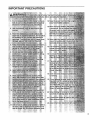
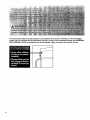
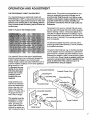
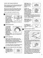
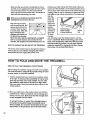
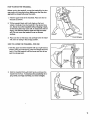
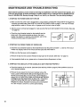
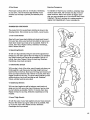
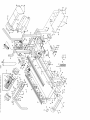
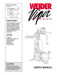
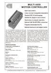
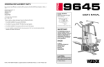
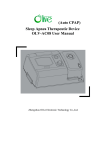
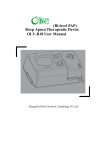
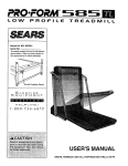
W LD
Model No. WLTL31571
Serial No.
Serial
Number
Decal
SEP08 1991
QUESTIONS?
As a manufacturer, we are committed to providing complete
customer satisfaction. If you
have questions, or find that there
are missing or damaged parts,
we will guarantee complete satisfaction through direct assistance from our factory.
TO AVOID UNNECESSARY DELAYS, PLEASE CALL DIRECT TO
OUR TOLL-FREE CUSTOMER
HOT LINE. The trained technicians on our Customer Hot Line
will provide immediate assistance, free of charge to you.
CUSTOMER
HOT LINE:
1-800-999-3756
Mon.-Fri.,
6 a.m.-6 p.m. MST
USER'S MANUAL
TABLE OF CONTENTS
IMPORTANT PRECAUTIONS .................................................................
BEFORE YOU BEGIN ........................................................................
ASSEMBLY ...............................................................................
OPERATION AND ADJUSTMENT
.............................................................
HOW TO FOLD AND MOVE THE TREADMILL ..................................................
MAINTENANCE AND TROUBLE-SHOOTING
...................................................
CONDITIONING GUIDELINES ........................
: .......................................
ORDERING REPLACEMENT PARTS ..................................................
LIMITED WARRANTY ...............................................................
3
5
6
7
10
12
14
Back Cover
Back Cover
Note: An EXPLODED DRAWING and a PART LIST are attached to the center of this manual. Save the
EXPLODED DRAWING and PART LIST for future reference.
2
IMPORTANT
PRECAUTIONS
21
:..
........
:
:,.
The decal shown below has been placed on your treadmill, if the decal is missing, or if it is not legible,
please call our Customer Service Department, toll-free, to order a free replacement decal (see ORDERING
REPLACEMENT PARTS on the back cover of this manual). Apply the decal in the location shown.
BEFORE YOU BEGIN
Thank you for selecting the WESJ,.O CADENCE ° LX 15
treadmill. The CADENCE LX 15 treadmill combines
advanced technology with innovative design to let you
enjoy an excellent form of cardiovascular exercise in
the convenience and privacy of your home. And when
you're not exercising, the unique CADENCE LX 15 can
be folded up, requiring less than half the floor space of
other treadmills.
at 1-800-999-3756, Monday through Friday, 6 a.m.
until 6 p.m. Mountain Time (excluding holidays). To
help us assist you, please note the product model
number and serial number before calling. The model
number of the treadmill is WLTL31571. The serial
number can be found on a decal attached to the treadmill (see the front cover of this manual for the location).
Before reading further, please review the drawing
below and familiarize yourself with the parts that are
labeled.
For your benefit, read this manual carefully before
using the treadmill. If you have additional questions,
please call our Customer Service Department toll-free
Water Bott!e Holder
-Towel Rack
(Water Bottle i_'
Accesso
Han0ra,
j \:,
Storage Latch
Walking
_
RIG.T
SIDE
_
i i
Foo'
ill
l
Upright
!
L
circuit
Breaker
Cord
Power
Rear Roller
Adjustment Bolt
BACK
\
Incline Leg
Cushioned Walking Platform
for maximum exercise comfort
5
ASSEMBLY
Assembly requires two people. Set the treadmill in a cleared area and remove all packing materials. Do not
dispose of the packing materials until assembly is completed. Assemblyrequires
and your own phillips screwdriver _===_
.
lw-
the included allen wrench=_
With the help of a second person, carefully lay the
treadmill on its right side as shown (refer to the drawing
on page 5 to identify the right side).
Insert one of the Extension Legs (41) into the treadmill as
shown. Make sure that the Base Pad (36) is on the indicated side of the Extension Leg. Attach the Extension
Leg with an Extension Leg Screw (34).
Attach the other Extension Leg (41) as described above.
With the help of a second person, carefully raise the
treadmill to the upright position so the Extension Legs
(41) are resting flat on the floor.
/
...._"34
=
Refer to HOW TO LOWER THE TREADMILL FOR USE
on page 11. Follow the instructions instep 2 to lower the
treadmill.
Attach the Storage Latch (12) to the left Upright (14) with
two Latch Screws (13). Be careful not to overtighten the
Latch Screws.
.
Remove the backing from the Adhesive Clip (74). Press
the Adhesive Clip onto the base of the Uprights (14) in
the indicated location. Press the Allen Wrench (73) into
the Adhesive Clip.
I
73
74
6
4. Make sure that all parts are tightened before you use the treadmill. To protect the floor or carpet, place
a mat under the treadmill.
OPERATION
THE PERFORMANT
AND ADJUSTMENT
LUBE TM WALKING BELT
Your treadmill features a walking belt coated with
PERFORMANT LUBE TM, a high-performance lubricant.
Important: Never apply silicone spray or other substances to the walking belt or the walking platform.
They will deteriorate the walking belt and cause excessive wear.
electric shock. This product is equipped with a cord
having an equipment-grounding conductor and a
grounding plug. Plug the power cord into a surge
protector, and plug the surge protector into an appropriate outlet that is properly installed and
grounded in accordance with all local codes and
ordinances.
This product is for use on a nominal 120-volt circuit,
and has a grounding plug that looks like the plug illustrated in drawing 1 below. A temporary adapter that
looks like the adapter illustrated in drawing 2 may be
used to connect the surge protector to a 2-pole receptacle as shown in drawing 2 if a properly grounded outlet is not available.
HOW TO PLUG IN THE POWER CORD
The temporary adapter should be used only until a
properly grounded outlet (drawing 1) can be installed
by a qualified electrician.
The green-colored rigid ear, lug, or the like extending
from the adapter must be connected to a permanent
ground such as a properly grounded outlet box cover.
Whenever the adapter is used it must be held in place
by a metal screw. Some 2-pole receptacle outlet box
covers are not grounded. Contact a qualified electrician to determine if the outlet box cover is
grounded before using an adapter.
Your treadmill, like any other type of sophisticated
electronic equipment, can be seriously damaged by
sudden voltage changes in your home's power.
Voltage surges, spikes, and noise interference can resuit from weather conditions or from other appliances
being turned on or off.
To decrease the possibility of your tread1
mill being damaged,
Grounded Outlet Box
always use a surge
protector (not included) with your
treadmill.
I .l
This product must be
grounded. If it should
malfunction or break
down, grounding provides a path of least resistance for electric current to reduce the risk of
. Grounding
Pin
L_"
Surge protectors are
sold at most hardware
stores and department
stores. Use only a ULlisted surge protector,
rated at 15 amps, with a
14-gauge cord of five
feet or less in length.
Treadmill Power
__._unding
Plug
_Grounded Outlet
/Grounded
Outlet Box
,__,Adapter
0.
(_
I(
/_
,
,,Grounding Pin
Grounding Plug
Surge Protector
Metal Screw
7
DIAGRAM OF THE CONSOLE
Speed Control
_
/
Monitor Displays
/=,44
|PM
HEART
RATE
TRAINING
ZONES
rING ZONE5
e TsJm
r--] r--ff--l r--] l_HSI
1311_C:3r"]r-l_
r---n
r-nr-n_ r-nii;i_:!:;_
, r--II---_ r-'3 r--I r-'l r--l_L_:i_i
CUSTOMERSERVICE
I tO0 999 3756
RESET
OPERATION
Clip
_
0
INilItT
KIY
O
AISII'SPIID
O
S][TIPEED
INote:If there' is a thin sheet ¢
clear plastic on the face of th_
console, remove it.
BATTERY INSTALLATION
The console requires three "AA" batteries (not
included); alkaline batteries are recommended. To
install batteries, first open the battery cover as shown
in the drawing at the right.
Press three batteries into the battery compartment,
with the negative ends of the batteries (marked "-")
touching the springs. Close the battery cover.
8
Battery Cover
STEP BY STEP CONSOLE OPERATION
Before operating the console, make sure that the power
cord is properly plugged in. (See HOW TO PLUG IN
THE POWER CORD on page 7.)
Step onto the foot rails of the treadmill. Next, find the
clip attached to the key (see the drawing on page 8).
Slide the clip onto the waistband of your clothing.
Follow the steps below to operate the console.
n
Insert the key fully into the power switch.
Inserting the key will
M
not turn on the displays. The displays will
turn on when the
ON/RESET button is
pressed or when the
walking belt is started.
Note: If you just installed batteries, the displays will
already be on.
19
,,o,,,,.,,,, zo..
RESET position.
Note: Each time
the walking belt is
stopped, the
speed control
must be turned to
the RESET position before the walking belt can
be restarted.
Start the walking belt.
After you have turned the speed control to the
RESET position, turn it slowly clockwise until the
walking belt begins to move at slow speed.
Carefully step onto the walking belt and begin exercising. Change the speed of the walking belt as desired by turning the speed control.
To stop the walking belt, step onto the foot rails and
turn the speed control to the RESET position.
Follow your progress with the monitor displays.
DISTANCE displaym
This display shows thp
total distance that you
have walked or run, in
miles.
DISTANCE
t"1
CAL/FAT CAL
display--This display
shows the approximate
numbers of both ca/o- •
ties and fat calories you
have burned (see FAT
BURNING on page 14
for an explanation of fat calories).
onds, the display will change from
the other. Indicators in the display
number is currently displayed.
SPEED display--This
display shows the speed
of the walking belt, in
miles per hour.
The displays can be
reset, if desired, by
pressing the ON/RESET
button.
Reset the speed control.
Turn the speed
control cou nterclockwise to the
TIME display--This
display shows the total
time that you have
walked or run on the
treadmill.
I
PuLse
ators
.
Every seven secone number to
will show which
SPEED
" u.3.
m _UI
OI_RESET
Measure your pulse, if desired.
To use the pulse sensor, stand on the foot rails and
place your thumb
on the pulse sensor as shown.
Pulse
Sensor
The pulse sensor
is pressure-activated; fully press
down the pulse
sensor. Do not
press too hard,
or the circulation In your thumb will be restricted, and your
pulse will not be detected. Next, slightly raise your
thumb until the heartshaped indicator in the
PULSE
PULSE display flashes
F/
F/
steadily. Hold your
thumb at this level.
ALj'FAT C,AI.
After 5 to 10 seconds,
Indicator
your pulse will be
shown. Hold your
thumb on the sensor for another 15 seconds for the
most accurate reading. If the displayed pulse appears to be too high or too low, or if your pulse is
not displayed, lift your thumb off the sensor and
allow the display to reset. Press down again on the
sensor as described above.
9
Make sure that your thumb is positioned as shown,
and that you are applying the proper amount of pressure to the pulse sensor. Try the sensor several
times until you become familiarwith it. Remember to
stand still while measuring your pulse.
When you are finished exercising,
walking belt and remove the key.
stop the
Step onto the foot rails,
stop the walking belt, and
remove the key from the
console. Store the key in
a secure place. After the
key is removed, the
displays will remain on
for about five minutes.
Note: Any time that the walking belt is stopped
and no console buttons are pressed for five
minutes, the displays will automatically turnoff.
HOW TO CHANGE THE INCLINE OF THE TREADMILL
Hold the rear roller endcap with both hands. When the
back end of the treadmill is in the lowest position, the incline is about 10%. Raise the back end until it clicks into
positiorj. (Note: It may be necessary to shake the treadmill lightly so that it clicks into position.) The incline will
then be
about 5%.
Raise the
back end
again until
it clicks into
position.
The incline
Hold the Rear
will then be
Roller Endcap
.
Incline
about 3%.
in these locations
Leg
To lower
the back
end, first raise it past the highest position, and then
lower it. CAUTION: Before exercising, push on the
back of the treadmill to make sure tl_at the incline
legs are locked in position. Do not place objects
under the treadmill to change the incline; change
the incline only as described above.
The incline of the treadmill can be changed by raising or
lowering the back end. Before changing the incline,
remove the key and unplug the power cord.
4_
HOW TO FOLD AND MOVE THE TREADMILL
HOW TO FOLD THE TREADMILL
FOR STORAGE
Before folding the treadmill, unplug the power cord. Caution:
You must be able to safely lift 45 pounds (20 kg) in order
to raise, lower, or move the treadmill.
.
Hold the treadmill with your hands in the locations shown
at the right. To decrease the possibility
of injury, bend
your legs and keep your back straight. As you raise
the treadmill, make sure to lift with your legs rather
than your back. Raise the treadmill about halfway to the
vertical position.
.
Move your right hand to the position shown and hold the
treadmill firmly. Raise the treadmill until the storage latch
closes over the catch. Make sure that the storage latch
is fully engaged over the catch.
To protect the floor or carpet from damage, place a
mat under the treadmill. Keep the treadmill out of
direct sunlight. Do not leave the treadmill in the storage position in temperatures above 85 ° Fahrenheit.
10
Engaged
HOW TO MOVE THE TREADMILL
Before moving the treadmill, convert the treadmill to the storage position as described above.JVlake sure that the storage latch is closed fully over the catch.
1. Hold the upper ends of the handrails. Place one foot on
the base as shown.
2. Tilt the treadmill back until it rolls freely on the front
wheels. Carefully move the treadmill to the desired location. Never move the treadmill without tipping it back,
or the base pads may come off. To reduce the risk of
injury, use extreme caution while moving the treadmill. Do not move the treadmill over an uneven
surface.
3. Place one foot on the base, and carefully lower the treadmill until it is resting in the storage position.
HOW TO LOWER THE TREADMILL
Base
Front Wheels
FOR USE
1. Hold the upper end of the treadmill with your right hand as
shown. Using your left thumb, press the storage latch and
hold it. Pivot the treadmill until the frame and foot rail are
past the storage latch.
2. Hold the treadmill firmly with both hands, and lower the
treadmill to the floor. To decrease the possibility of injury, bend your legs and keep your back straight.
11
MAINTENANCE
AND TROUBLE-SHOOTING
Most treadmill problems can be solved by following the step_,bel0w. Find the symptom that applies, and
follow the steps listed. If further assistance is needed, please call our Customer Service Department tollfree at 1-800-999-3756, Monday through Friday, 6 a.m. until 6 p.m. Mountain Time (excluding holidays).
1. SYMPTOM: THE POWER DOES NOT TURN ON
a. Make sure that the power cord is plugged into a surge protector, and that the surge protector is plugged into
a properly grounded outlet. (See HOW TO PLUG IN THE POWER CORD on page 7.) Use only a UL-listed
surge protector, rated at 15 amps, with a 14-gauge cord of five feet or less in length.
b. After the power cord has been plugged in, make sure that the key is fully inserted into the_onsole. (See step
1 on page 9.)
C.
Check the circuit breaker located on the treadmill near the
power cord. If the switch protrudes as shown, the circuit
breaker has tripped. To reset the circuit breaker, wait for five
minutes and then press the switch back in.
C
Tdpped
Reset
2. SYMPTOM: THE POWER TURNS OFF DURING USE
a. Check the circuit breaker located on the treadmill frame near the power cord (see 1. c. above). If the circuit
breaker has tripped, wait for five minutes and then press the switch back in.
b. Make sure that the power cord is plugged in.
c. Remove the key from the console. Reinsert the key fully into the console. (See step I on page 9.)
d. If the treadmill still will not run, please call our Customer Service Department, toll-free.
3. SYMPTOM: THE DISPLAYS OF THE CONSOLE DO NOT FUNCTION PROPERLY
a. Check the batteries in the console. (See BATTERY INSTALLATION on page 8.) Most problems are the result of drained batteries.
b. Remove the six screws from the hood. Carefully remove the
hood. Locate the Reed Switch (86) and the Magnet (87) on the
left side of the Pulley (85). Turn the Pulley until the Magnet is
aligned with the Reed Switch. Make sure that the gap between
the Magnet and the Reed Switch is about 1/8". If necessary,
loosen the Screw (35) and move the Reed Switch slightly.
Retighten the Screw. Re-attach the hood, and run the treadmill
for a few minutes to check for a correct speed reading.
12
"
Top
View
_85
4. SYMPTOM:
THE WALKING
BELT SLOWS WHEN WALKED ON
a. Use only a UL-listed surge protector, rated at 15 amps, with a 14-gauge cord of five feet or less in length.
b.
If the walking belt is overtightened, treadmill performance may
decrease and the walking belt may be permanently damaged.
Remove the key and UNPLUG THE POWER CORD. Using the
allen wrench, turn both rear roller adjustment bolts counterclockwise, 1/4 of a turn. When the walking belt is properly tightened,
you should be able to lift each side of the walking belt 2 to 3
inches off the walking platform. The center of the walking belt
should just touch the walking platform. Be careful to keep the
walking belt centered. Plug in the power cord, insert the key and
run the treadmill for a few minutes. Repeat until the walking belt
is properly tightened.
Rear Roller Adjustment Bolts
c. If the walking belt still slows when walked on, please call our toll-free Customer Service Department.
5. SYMPTOM:
THE WALKING BELT IS OFF-CENTER
WHEN WALKED ON
a. If the walking belt has shifted to the left, first remove the key and
UNPLUG THE POWER CORD. Using the allen wrench, turn the
left rear roller adjustment bolt clockwise, and the right bolt counterclockwise, 1/4 of a turn each. Be careful not to overtighten the
walking belt. Plug in the power cord, insert the key and run the
treadmill for a few minutes. Repeat until the walking belt is centered.
b. if the walking belt has shifted to the right, first remove the key
and UNPLUG THE POWER CORD. Using the allen wrench,
turn the left rear roller adjustment bolt counterclockwise, and the
right bolt clockwise, 1/4 of a turn each. Be careful not to overtighten the walking belt. Plug in the power cord, insert the key
and run the treadmill for a few minutes. Repeat until the walking
belt is centered.
C.
a
b
If the walking belt slips when walked on, first remove the key
and UNPLUG THE POWER CORD. Using the allen wrench,
turn both rear roller adjustment bolts clockwise, 1/4 of a turn.
When the walking belt is correctly tightened, you should be able
to lift each side of the walking belt 2 to 3 inches off the walking
platform. The center of the walking belt should just touch the
walking platform. Be careful to keep the walking belt centered.
Plug in the power cord, insert the key and run the treadmill for a
few minutes. Repeat until the walking belt is properly tightened.
6. SYMPTOM:
THE INCLINE SYSTEM STICKS
a. Raise the treadmill to the storage position. (See HOW TO FOLD THE TREADMILL FOR STORAGE on page
10.) Pivot the incline leg several times to break in the incline system.
CONDITIONING
GUIDELINES
Fat Burning
To burn fat effectively, you must exercise at a relatively
low intensity level for a sustained period of time. During
the first few minutes of exercise, your body uses easily
accessible carbohydrate calories for energy. Only after
the first few minutes does your body begin to use stored
fat calories for energy. If your goal is to burn fat, adjust
the speed and incline of the treadmill until your heart
rate is near one of the lower two numbers in your training zone. It may also be helpful to set the speed control
on the console to FAT BURN to hel_15
you maintain the
proper intensity level. (See page 9.)
Aerobic Exercise
The following guidelines will help you to plan your exercise program. Remember--these are general guidelines only. For more detailed exercise information, obtain a reputable book or consult your physician.
EXERCISEINTENSITY
Whether your goal is to burn fat or to strengthen your
cardiovascular system, the key to achieving the desired
results is to exercise with the proper intensity. The
• proper intensity level can be found by using your heart
rate as a guide. The chart below shows recommended
heart rates for fat burning and aerobic exercise.
If your goal is to strengthen your cardiovascular system, your exercise must be "aerobic." Aerobic exercise
is activity that requires large amounts of oxygen for
prolonged periods of time. This increa.ses the demand
on the heartto pump blood to the mu'gcles, and on the
lungs to oxygenate the blood. For aerobic exercise, adjust the speed and incline of the treadmill until your
heart rate is near the higher number in your training
zone. It may also be helpful to set the speed control on
the console to AEROBIC to help you maintain the
proper intensity level. (See page 9.)
High Performance
BPM
HEART RATE TRAINING
ZONES
Athletic Conditioning
If your goal is high performance athletic conditioning,
set the speed control on the console to PERFORMANCE to help you maintain the proper intensity level.
(See page 9.) Note: During the first few weeks of your
exercise program, keep your heart rate near the low
end of your training zone.
WORKOUT GUIDELINES
Each workout should include the following three parts:
20
30
40
50
60
70
80
A Warm-up
To find the proper heart rate for you, first find your age
at the bottom of the chart (ages are rounded off to the
nearest ten years). Next, find the three numbers above
your age. The three numbers are your "training zone."
The lower two numbers are recommended heart rates
for fat burning; the higher number is the recommended
heart rate for aerobic exercise.
14
To measure your heart rate during exercise, use the
pulse sensor on the console. (See page 9.) if your
heart rate is too high or too low, adjust the speed or incline of the treadmill as needed.
Start each workout with 5 to 10 minutes of stretching
and light exercise. A proper warm-up increases your
body temperature, heart rate, and circulation in preparation for strenuous exercise.
Training Zone Exercise
After warming up, increase the intensity of your exercise until your heart rate is in your training zone for 20
to 60 minutes. (During the first few weeks of your exercise program, do not keep your heart rate in your training zone for longer than 20 minutes.) Breathe regularly
and deeply as you exercise--never
hold your breath.
A Cool-down
Exercise Frequency
Finish each workout with 5 to 10 minutes of stretching
to cool down. This will increase tl).e flexibility of your
muscles and will help to prevent post-exercise problems.
To maintain or improve your condition, complete three
workouts each week, with at least one day of rest between workouts. After a few months of regular exercise, you may complete up to five workouts each week
if desired. The key to success is to make exercise a
regular and enjoyable part of your everyday fife.
SUGGESTED
STRETCHES
The correct form for several basic stretches is shown in the
drawings below. Move slowly as you stretch---never bounce.
1. Toe Touch Stretch
Stand with your knees bent slightly and slowly bend forward
from your hips. Allow your back and shoulders to relax as you
reach down toward your toes as far as possible. Hold for 15
counts, then relax. Repeat 3 times. Stretches: Hamstrings,
back of knees and back.
2
2. Hamstring Stretch
Sit with one leg extended. Bring the sole of the opposite foot
toward you and rest it against the inner thigh of your extended
leg. Reach toward your toes as far as possible. Hold for 15
counts, then relax. Repeat 3 times for each leg. Stretches:
Hamstrings, lower back and groin.
3
3. Calf/Achilles Stretch
With one leg in front of the other, reach forward and place your
hands against a wall. Keep your back leg straight and your
back foot flat on the floor. Bend your front leg, lean forward and
move your hips toward the wall. Hold for 15 counts, then relax.
Repeat 3 times for each leg. To cause further stretching of the
achilles tendons, bend your back leg as well. Stretches:
Calves, achilles tendons and ankles.
4
4, Quadriceps Stretch
With one hand against a wall for balance, reach back and
grasp one foot with your other hand. Bring your heel as close
to your buttocks as possible. Hold for 15 counts, then relax.
Repeat 3 times for each leg. Stretches: Quadriceps and hip
muscles.
5, Inner Thigh Stretch
Sit with the soles of your feet together and your knees outward.
Pull your feet toward your groin area as far as possible. Hold
for 15 counts, then relax. Repeat 3 times. Stretches:
Quadriceps and hip muscles.
15
III
I
II
I
REMOVE THIS EXPLODED DRAWING AND
PART LIST FROM THE MANUAL. Save this
EXPLODED DRAWING and PART LIST for
future reference.
Note: Specifications are subject to change without notice. For information about
ordering replacement parts, see the back cover of the user's manual.
PART LISTmModel
Key No. Qty.
Description
No. WLTL31571
.
R0997A
Key No.
Qty.
Description
50
51
52
53
: 54
55
2
1
1
1
1
2
4
1
2
2
1
1
2
2
2
2
2
1
1
1
2
2
1
1
1
1
1
4
1
1
1
1
1
1
1
1
1
1
1
8
11
1
1
1
1
1
Belt Guide
Belly Pan
Releasable Tie
Cable Tie Clamp
Motor Belly Pan
Handrail Endcap
8" Cable Tie
Incline Leg Spacer (long)
Incline Leg Bolt
Ratchet Screw._
Ratchet Spring
Ratchet
Solid Isolator
Incline Leg Spacer (short)
Incline Wheel Bolt'
Incline Wheel
Incline Wheel Nut
1
2
3
4
5
6
1
1
1
1
4
1
Key/Clip
Ground Nut
Console Ground Screw
Ratchet Screw
Rear Isolator Screw
Left Console Attachment
7
8
9
10
11 *
12
13
14
15
16
17
18
19*
20
21
22
23
24
25
26
27
28
29
30
31
1
1
1
1
1
1
2
1
1
11
1
1
1
1
1
3
1
1
1
1
3
1
1
2
1
Speed Control Knob
Speed Potentiometer
Battery Cover
Strain Relief
Console Assembly
Storage Latch
Latch Screw
Upright Base
Frame
Washer
Motor Belt
Motor Swivel Nut
. Motor/Pulley/FlywheeVFan
Pulley/Flywheel/Fan
Motor
Motor Tension Bolt
Motor Tension Washer
Motor Tension Star Washer
Motor Swivel Bolt
Console Plate
Ground Wire Screw
Hood
Hood Shield
Screw
Latch Decal
56
57
58
59
60
61
62
63
64
65
66
67
68
69
70
71
72
73
74
75
76
77
78
79
80
32
33
34
35
36
37
38
39
40
41
42
43
44
45
46
1
2
2
32
4
2
2
7
1
2
1
1
1
2
4
Right Console Attachment
Frame Pivot Bolt
Extension Leg Screw
Electronics Screw
Base Pad
Wheel Bolt
Wheel
Wheel Nut
Controller
Extension Leg
Circuit Breaker
Power Cord Grommet
Power Cord
Upright Spacer
Isolator
81
82
83
84
85
86
87
88
89
90
91
92
93
#
#
47
48
49
14
1
1
Belly Pan Fastener
Choke
Motor Locknut
Incline Leg Plate
Ground Wire
.:
Incline Leg
Upright Pivot Washer
Rear Roller Adj. Bolt
Rear Roller Endcap
Allen Wrench
Adhesive Clip
Left Foot Rail
Rear Roller
Platform Screw
Latch Catch
Walking Platform
Walking Belt
Front Roller AdjustmentBolt
Shock
Right Foot Rail
Sensor Clip
Front Roller/Pulley
Reed Switch
Magnet
Console Wire Harness
Console Plate Screw
Console Screw
Reed Switch Screw
11 3/4" Wire Tie
Upright Plug
14" Wire Harness
User's Manual
* Includes all parts shown in the box
# These parts are not illustrated
(
/ == .Y
/
.,., >.]
/
/'\
/
_
\
I
//=
--/-'--"
'\,
"\
\
',,,
_"\,
m_
L
/
,3
/
).
/
//,
1
\/-"t
ORDERING
REPLACEMENT
PARTS
To order replacement parts, call_our Customer Service Departme_,t toll-free at 1-800-999-3756, Monday through
Friday, 6 a.m. until 6 p.m. Mountain Time (excluding holidays). When ordering parts, please be prepared to give
the following information:
• The MODEL NUMBER OF THE PRODUCT (WLTL31571).
= The NAME OF THE PRODUCT (WESLO ®CADENCE LX i5 treadmill).
• The SERIAL NUMBER OF THE PRODUCT (see the front cover of this manual).
• The KEY NUMBER OF THE PART(S) (see the EXPLODED DRAWING and PART LIST attached to the center
of this manual).
• The DESCRIPTION
of this manual).
OF THE PART(S) (see the EXPLODED DRAWING and PART LIST attached to the center
If possible, place the treadmill near your telephone for easy reference when calling.
WESLO is a registered trademark of ICON Health & Fitness, Inc.
I
LIMITED WARRANTY
ICON Health & Fitness, Inc. (ICON), warrants this product to be free from defects in workmanship and
material, under normal use and service conditions, for a period of ninety (90) days from the date of purchase. This warranty extends only to the original purchaser. ICON's obligation under this warranty is limited to replacing or repairing, at ICON's option, the product at one of its authorized service centers. All
products for which warranty claim is made must be received by ICON at one of its authorized service
centers with all freight and other transportation charges prepaid, accompanied by sufficient proof of purchase. All returns must be pre-authorized by ICON. This warranty does not extend to any product or
damage to a product caused by or attributable to freight damage, abuse, misuse, improper or abnormal
usage or repairs not provided by an ICON authorized service center, to products used for commercial or
rental purposes, or to products used as store display models. No other warranty beyond that specifically
set forth above is authorized by ICON.
ICON is not responsible or liable for indirect, special or consequential damages arising out of or in connection with the use or performance of the product or damages with respect to any economic loss, loss
of property, loss of revenues or profits, loss of enjoyment or use, costs of removal, installation or other
consequential damages of whatsoever nature. Some states do not allow the exclusion or limitation of incidental or consequential damages. Accordingly, the above limitation may not apply to you.
The warranty extended hereunder is in lieu of any and all other warranties and any implied warranties of
merchantability or fitness for a particular purpose is limited in its scope and duration to the terms set
forth herein. Some states do not allow limitations on how long an implied warranty lasts. Accordingly,
the above limitation may not apply to you.
This warranty gives you specific legal rights. You may also have other rights which vary from state to state.
ICON HEALTH & FITNESS, INC., 1500 S. 1000 W., LOGAN, UT 84321-9813
Part No. 140805 G03134-C
R0997A
Printed in USA © 1997 ICON Health & Fitness, Inc.