1
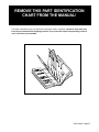
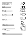
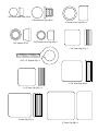
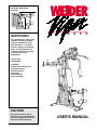
Model No. WESY60400
Serial No.
Serial Number Decal
QUESTIONS?
As a manufacturer, we are committed to providing complete
customer satisfaction. If you
have questions, or find that
there are missing or damaged
parts, we will guarantee you
complete satisfaction through
our Customer Service
Department.
Please CALL:
0345-089009
Or WRITE:
ICON Fitness Lifestyle Ltd.
Greenwich House
223 North Street
Sheepscar
West Yorkshire
Leeds LS7 2AA
CAUTION
Read all precautions and instructions in this manual before
using this equipment. Save this
manual for future reference.
USER'S MANUAL
TABLE OF CONTENTS
IMPORTANT PRECAUTIONS . . . . . . . . . . . . . . . . . . . . . . . . . . . . . . . . . . . . . . . . . . . . . . . . . . . . . . . . . . . . . .2
BEFORE YOU BEGIN . . . . . . . . . . . . . . . . . . . . . . . . . . . . . . . . . . . . . . . . . . . . . . . . . . . . . . . . . . . . . . . . . . .3
ASSEMBLY . . . . . . . . . . . . . . . . . . . . . . . . . . . . . . . . . . . . . . . . . . . . . . . . . . . . . . . . . . . . . . . . . . . . . . . . . . .4
ADJUSTMENT . . . . . . . . . . . . . . . . . . . . . . . . . . . . . . . . . . . . . . . . . . . . . . . . . . . . . . . . . . . . . . . . . . . . . . . .15
TROUBLE-SHOOTING AND MAINTENANCE . . . . . . . . . . . . . . . . . . . . . . . . . . . . . . . . . . . . . . . . . . . . . . . . .18
CABLE DIAGRAM . . . . . . . . . . . . . . . . . . . . . . . . . . . . . . . . . . . . . . . . . . . . . . . . . . . . . . . . . . . . . . . . . . . . .19
ORDERING REPLACEMENT PARTS . . . . . . . . . . . . . . . . . . . . . . . . . . . . . . . . . . . . . . . . . . . . . . .Back Cover
Note: A PART IDENTIFICATION CHART and a PARTS LIST/EXPLODED DRAWING are attached at the centre
of this manual. Remove them before beginning assembly.
IMPORTANT PRECAUTIONS
WARNING: To reduce the risk of serious injury, read the following important precautions before using
the home gym system.
1. Read all instructions in this user's manual
and in the accompanying literature before
using the weight system.
7. Always wear athletic shoes for foot protection.
8. Never release the press arms, leg lever, lat
bar or nylon strap whilst weights are raised.
The weights will fall with great force.
2. Use the weight system only on a level surface. Cover the floor beneath the weight system for protection.
9. Always stand on a foot plate when performing
an exercise that could cause the weight system to tip.
3. Inspect and tighten all parts each time you
use the weight system. Replace any worn
parts immediately.
10. Always disconnect the lat bar from the weight
system when performing an exercise that
does not use the lat bar.
4. Keep children under 12 away from the weight
system at all times.
11. The resistance cylinders become very hot
during use. Allow the cylinders to cool before
touching them.
5. Inspect all cables before each use. Make sure
that the cables remain on the pulleys at all
times. If the cables bind whilst you are exercising, stop immediately and make sure that
the cables are on all of the pulleys. Replace
all cables every two years.
12. If you feel pain or dizziness at any time whilst
exercising, stop immediately and begin cooling down.
13. The weight system is intended for in-home
use only. Do not use this treadmill in any
commercial, rental, or institutional setting.
6. Keep hands and feet away from moving
parts.
WARNING: Before beginning this or any exercise program, consult your physician. This is especially
important for persons over the age of 35 or persons with pre-existing health problems. Read all
instructions before using. ICON assumes no responsibility for personal injury or property damage
sustained by or through the use of this product.
2
BEFORE YOU BEGIN
tional questions, please call our Customer Service
Department. To help us assist you, please note the
product model number and serial number before calling. The model number is WESY60400. The serial
number can be found on a decal attached to the
VIPER 2000 (see the front cover of this user's manual).
Thank you for selecting the versatile WEIDER® VIPER
2000. The VIPER 2000 offers a selection of weight
stations designed to develop every major muscle
group of the body. Whether your goal is to tone your
body, build dramatic muscle size and strength, or
improve your cardiovascular system, the VIPER 2000
will help you to achieve the specific results you want.
Before reading further, please review the drawing
below and familiarise yourself with the parts that are
labelled.
For your benefit, read this manual carefully before
using the WEIDER® VIPER 2000. If you have addi-
ASSEMBLED
DIMENSIONS:
Height: 75 1/2 in.
Width: 55 3/4 in.
Length: 72 in.
High Pulley Station
Lat Bar
Arms
VKR Arms
Backrest
Stepper
Resistance Cylinders
Leg Lever
Weight Stack
Low Pulley Station
Foot Plate
Weight Pin
3
ASSEMBLY
Before beginning assembly, carefully read the
following information and instructions:
• Tighten all parts as you assemble them, unless
instructed to do otherwise.
• Place all parts of the VIPER 2000 in a cleared
area and remove the packing materials; do not
dispose of the packing materials until assembly is
completed.
THE FOLLOWING TOOLS (NOT INCLUDED) ARE
REQUIRED FOR ASSEMBLY:
• Two (2) adjustable spanners
• Read each assembly step before you begin.
• One (1) standard screwdriver
• For help identifying the small parts used in
assembly, use the PART IDENTIFICATION
CHART located in the centre of this manual.
Note: Some small parts may have been preattached for shipping purposes. If a part is not in
the parts bag, check to see if it has been preattached.
• One (1) phillips screwdriver
• One (1) rubber mallet
• Lubricant, such as grease or petroleum jelly,
and soapy water will also be needed.
Assembly will be more convenient if you have the
following tools: A socket set, a set of open-end or
closed-end wrenches, or a set of ratchet wrenches.
• As you assemble the VIPER 2000, be sure that
all parts are oriented as shown in the drawings.
1. Before you begin, make sure that you have
carefully read the instructions at the top of
this page.
1
20
11
Press a 2” Inner Cap (27) into the Base (4).
4
Attach the Pulley Plate (20) to the Base (4) with
two 5/16” x 2 3/4” Bolts (11), two 5/16” Flat
Washers (8), and two 5/16” Nylon Locknuts (3).
3
8
1
Insert the two 5/16” x 2 1/2” Carriage Bolts (1) up
through the Base (4).
27
2. Press the two 2” Outer Caps (88) onto the
Stabiliser (5).
2
Bracket
Low Side
Insert two 5/16” x 2 3/4” Carriage Bolts (14) and
one 5/16” x 2 1/2” Carriage Bolt (1) up through
the Stabiliser (5). Slide the end of the Base (4)
and the Rear Upright (82) onto the two 5/16” x
2 3/4” Carriage Bolts (14). Make sure that the
Rear Upright is turned as shown. Thread 5/16”
Nylon Locknuts (3) onto the two Carriage Bolts.
Do not tighten the Nylon Locknuts yet.
82
11
86
8
88
3
Slide one end of the Brace (86) onto the 5/16” x
2 1/2” Carriage Bolt (1) in the Stabiliser (5). Thread
a 5/16” Nylon Locknut (3) onto the Carriage Bolt.
Do not tighten the Nylon Locknut yet.
3
5
4
88
Attach the other end of the Brace (86) to the Rear
Upright (82) with a 5/16” x 2 3/4” Bolt (11), a 5/16”
Flat Washer (8), and a 5/16” Nylon Locknut (3).
Do not tighten the Nylon Locknut yet.
1
4
14
3. Press the 1 1/4” Inner Cap (57) into the Front
Upright (42).
3
Single Hole
63
3
64
3
Attach the 1” Plastic Stop (64) to the centre hole
in the Stop Bracket (63) with a 5/16” x 1 1/2” Bolt
(24) and 5/16” Nylon Locknut (3).
24
8
57
Attach the Stop Bracket (63) to the Front Upright
(42) with a 5/16” x 2” Bolt (61), 5/16” Flat Washer
(8), and 5/16” Nylon Locknut (3).
61
Slide the Front Upright (42) onto the two 5/16” x
2 1/2” Carriage Bolts (1) in the Base (4). Thread
two 5/16” Nylon Locknuts (3) onto the Carriage
Bolts. Do not tighten the Nylon Locknuts yet.
42
4
3
1
4. Press two 2” Inner Caps (27) into the Top Frame
(67).
4
Attach the Top Frame (67) to the Front Upright (42)
with two 5/16” x 2 3/4” Bolts (11), 5/16” Flat
Washers (8), and 5/16” Nylon Locknuts (3). Do
not tighten the Nylon Locknuts yet.
11
11
8
11
8
8
67
Attach the Top Frame (67) to the Stop Bracket (63)
with a 5/16” x 2 3/4” Bolt (11), 5/16” Flat Washer
(8), and 5/16” Nylon Locknut (3). Do not tighten
the Nylon Locknut yet.
27
3
3
Attach the Top Frame (67) to the Rear Upright (82)
with two 5/16” x 2 3/4” Bolts (11), 5/16” Flat
Washers (8), and 5/16” Nylon Locknuts (3).
3
Tighten all Nylon Locknuts used in steps 2
through 4.
42
82
5
63
27
5. Press two 1 1/2” Bushings (93) into the Left Pedal
(90); press two 1 1/2” Bushings (93) into the
Right Pedal (89). Attach a Pedal Cover (92) to
each Pedal with a 1/2” Tap Screw (6).
5
92
6
92
6
89
Lubricate the pedal axles on the Rear Upright
(82). Slide the Right and Left Pedals (89, 90) onto
the right and left pedal axles. Note: Make sure
that the Pedals are on the correct sides; the
slotted brackets must be on the insides of the
Pedals. Hold a 1" Retainer (54) and 1" Round
Cover Cap (55) against the left pedal axle. The
teeth on the Retainer must bend toward the
Round Cover Cap. Tap the Retainer and Round
Cover Cap onto the pedal axle. Attach the Right
Pedal in the same manner.
Slotted
Brackets
93
82
Lubricate
90
54
93
55
6
6. Lubricate the cylinder axles on the Rear Upright
(82). Slide a 5/8” Spacer (97) and a Resistance
Cylinder (91) onto the right cylinder axle. Be sure
that the Spacer is turned as shown. Hold a 5/8"
Retainer (95) and 5/8" Round Cover Cap (96)
against the right cylinder axle. The teeth on the
Retainer must bend toward the Round Cover
Cap. Tap the Retainer and Round Cover Cap
onto the cylinder axle.
97
96
82—Lubricate
95
91
Attach a Resistance Cylinder (91) to the left cylinder axle in the same manner.
7. Raise the Left Pedal (90) and rest it on the hook
at the lower end of the left Resistance Cylinder
(91). The hook must be in one of the slots under
the Left Pedal.
7
Raise the Right Pedal (89) and rest it on the hook
at the lower end of the right Resistance Cylinder
(91). Make sure that the hooks are in the same
position under both Pedals.
91
89
Hooks
8. Set the two Weight Bumpers (19) on the indicated
plate on the Base (4). Align the holes in the
Weight Bumpers with the holes in the plate.
90
8
Stack nine Weights (25) on the Weight Bumpers
(19). Each Weight must be turned so the pin
groove is facing the Front Upright (42). The
holes in the Weights must be aligned with the
holes in the Weight Bumpers. CAUTION: Be
careful to avoid tipping the stack of Weights
until step 9 is completed.
Pin Groove
25
19
19
6
4
42
9. Press the Weight Tube Endcap (79) into the indicated end of the Weight Tube (80).
9
Upper Ends of
Weight Guides
have Holes
Insert the Weight Tube (80) into the stack of
Weights (25). Slide the tenth Weight (25) onto the
upper end of the Weight Tube. The Weight Tube
must be turned so the welded pin is in the pin
groove in the Weight.
72
Locate the lower ends of the Weight Guides (72)
(there are holes near the upper ends). Insert the
lower ends of the Weight Guides into the ten
Weights (25).
25
Pin
Groove
80
Welded Pin
79
25
10. Attach the upper ends of the Weight Guides (72)
to the Top Frame (67) with the 5/16” x 6” Bolt
(74), the two 1/2” x 3/4” Bushings (73), and a
5/16” Nylon Locknut (3).
10
73
3
67
74
72
11. Press two 1 3/4” Inner Caps (44) and two 1”
Round Inner Caps (49) into the Arm Frame (52).
11
Lubricate the upper axle on the Arm Frame (52).
Hold the axle between the two Arm Frame
Bushings (68). Set the Arm Frame Bushings and
the Arm Frame on the welded plate on the Top
Frame (67). Place the Arm Frame Bracket (69)
over the Arm Frame Bushings. Attach the Arm
Frame Bracket to the Top Frame with four 1/4” x
3/4” Screws (18) and 1/4” Nylon Locknuts (7).
18
Lubricate
69
49
68
67
49
52
44
42
7
7
44
12. Press two 1 3/4” Inner Caps (44) into each of the
Arms (46).
12
Apply lubricant to the lower axles on the Arm
Frame (52). Slide an Arm (46) onto one of the
axles. Hold two 1” Retainers (54) and a 1” Round
Cover Cap (55) against the lower end of the axle.
The teeth on the Retainers must bend toward
the Round Cover Cap (see inset drawing). Tap
the Retainers and Round Cover Cap onto the axle.
42
60
44
52—Lubricate
Attach the other Arm (46) to the Arm Frame (52) in
the same manner.
54
54
Insert the two 4 1/2” “L” Pins (60) down through the
indicated holes in the Arm Frame (52) and the
Arms (46).
44
46
55
46
44
44
52
54
55
13. Wet both Arms (46) with soapy water. Slide a 7 3/4”
Pad (45) onto each Arm.
13
46
Press a 1” Round Inner Cap (49) into the indicated
end of a 7” Handle (47). Wet the other end of the
Handle with soapy water and slide a Handgrip (12)
onto it. Insert the Handle into one of the Arms (46).
Attach the Handle with a 5/16” x 2 1/4” Bolt (33),
two 5/16” Flat Washers (8), a 1/2” x 3/8” Spacer
(51) and a 5/16” Nylon Locknut (3).
47
46
8
49
3
45
8
47
51
45
Attach a 7” Handle (47) to the other Arm (46) in the
same manner.
14. Attach a Large “U” Bracket (56) to one of the Arms
(46) with a 3/8” x 2 3/4” Bolt (70), 3/8” Flat Washer
(9), and 3/8” Nylon Locknut (21). Be sure that the
Cable Trap (59) is on the side shown.
12
14
33
59
21
56
Attach a Large “U” Bracket (56) to the other Arm
(46) in the same manner.
59
46
9
21
56
9
46
8
70
70
15. Attach the Wide Swivel Bracket (71) to the indicated bracket on the Top Frame (67) with a 5/16”
x 3 1/4” Bolt (35) and 5/16” Nylon Locknut (3). Do
not overtighten the Nylon Locknut; the Wide
Swivel Bracket must be able to swivel freely.
15
35
67
3
16. If the parts shown at the right have not been preassembled, follow the instructions below to
assemble them.
71
16
77
Attach the two “I” Plates (78) to two 4 1/2” Pulleys
(77) with two 3/8” x 1 3/4” Bolts (48) and 3/8”
Nylon Locknuts (21) as shown. Do not thread
the Nylon Locknuts all the way onto the Bolts
until assembly step 24 is completed.
48
78
21
77
78
17. IMPORTANT: As you assemble the Long Cable
(66) and the Short Cable (not shown), refer to
page 19 of this manual to make sure that the
Cables are properly routed.
17
66
65 77
65
9
Find the end of the Long Cable (66) that does not
have a rubber ball. Insert that end of the Long
Cable up through the indicated opening in the Top
Frame (67).
21
9
70
67
Lay the Long Cable (66) over a 4 1/2” Pulley (77).
Attach the Pulley inside the Top Frame (67) with a
3/8” x 2 3/4” Bolt (70), two 3/8” Flat Washers (9),
the two 1/2” x 1/2” Spacers (65), and a 3/8” Nylon
Locknut (21).
18
18. Remove the 3/8” x 1 3/4” Bolt (48), 3/8” Nylon
Locknut (21), and 3 1/2” Pulley (15) from the indicated bracket on the Top Frame (67). Insert the
end of the Long Cable (66) through the bracket
and down through the indicated hole.
Bracket
67
Hole
48
Reattach the 3 1/2” Pulley (15) to the bracket on
the Top Frame (67) with the 3/8” x 1 3/4” Bolt (48)
and 3/8” Nylon Locknut (21). Be sure that the
Long Cable is between the Pulley and the top
of the bracket.
9
21
15
66
19. Remove the 3/8” Nylon Locknut (21), 3/8” x 1 3/4”
Bolt (48), and 4 1/2” Pulley (77) from one end of
the “I” Plates (78). Route the Long Cable (66)
under the Pulley and reattach the Pulley to the “I”
Plates with the Bolt and Nylon Locknut.
19
67
71
15
48
59
Refer to the inset drawing. (Note: The Wide
Swivel Bracket [71] is attached to the Top Frame
[67]; it is shown disassembled for clarity.) Lay the
Long Cable (66) over a 3 1/2” Pulley (15). Attach
the Pulley and a Cable Trap (59) to the Wide
Swivel Bracket (71) with a 3/8” x 1 3/4” Bolt (48)
and 3/8” Nylon Locknut (21). Be sure that the
Cable Trap is turned to the indicated position.
66
21
66
77
48
21
20. Wrap the Long Cable (66) down around the 3 1/2”
Pulley (15) on the left Arm (46). Tighten the 3/8”
Nylon Locknut (21) and 3/8” x 1 3/4” Bolt (not
shown). Be sure that the Cable Trap (59) is
turned to the indicated position.
78
20
15
46
21
66
59
21. Note: The 4 1/2” Pulley (77) shown in this step is
preattached to the Adjustment “U” Bracket (75).
Attach the Adjustment “U” Bracket (75) to the
Front Upright (42) with the 5/16” x 3 1/4” Bolt
(35), a 5/16” Flat Washer (8), and a 5/16” Nylon
Locknut (3). Thread the Nylon Locknut onto
the Bolt only two complete turns.
21
3
8
48
42
75
Remove the 3/8” x 1 3/4” Bolt (48), 3/8” Nylon
Locknut (21), and 4 1/2” Pulley (77) from the
Adjustment “U” Bracket (75). Wrap the Long
Cable (66) around the Pulley as shown. Reattach
the Pulley to the Adjustment “U” Bracket with the
Bolt and Nylon Locknut.
21
35
22. Wrap the Long Cable (66) up around the 3 1/2”
Pulley (15) on the right Arm (46). Tighten the 3/8”
x 1 3/4” Bolt (48) and 3/8” Nylon Locknut (not
shown). Be sure that the Cable Trap (59) is
turned to the indicated position.
77
17
22
67
8
66
12
3
9
2
Attach the 5/16” x 3” Bolt (17), two 5/16” Flat
Washers (8), and a 5/16” Jam Nut (2) to the indicated hole in the Top Frame (67).
2
59
6
15
48
46
Slide the end of the Long Cable (66) onto the
5/16” x 3” Bolt (17). Tighten another 5/16” Jam
Nut (2) onto the Bolt.
10
66
23. Hold the indicated end of the Short Cable (23)
under the 3 1/2” Pulley (15) on the Front Upright
(42). Attach the 5/16” x 3 1/2” Bolt (87), two 5/16”
Flat Washers (8), the 1” Metal Spacer (22), and a
5/16” Nylon Locknut (3) to the Front Upright as
shown. Be sure that the Short Cable is
between the Pulley and the Metal Spacer.
Tighten the 3/8” Nylon Locknut (21) and 3/8” x
3 1/2” Bolt (not shown).
23
12
3
9
6
59
48
15
15
87
8
22
20
21
Wrap the Short Cable (23) up around the 3 1/2”
Pulley (15) on the Pulley Plate (20). Tighten the
3/8” Nylon Locknut (21) and 3/8” x 1 3/4” Bolt
(48). Make sure that the Cable Trap (59) is in
the 6 o’clock position.
23
3
8 42
24
24. Remove the 3/8” Nylon Locknut (21), 3/8” x 1 3/4”
Bolt (48), and 4 1/2” Pulley (77) from the lower
end of the “I” Plates (78). Route the Short Cable
(23) over the Pulley and reattach the Pulley to the
“I” Plates with the Bolt and Nylon Locknut.
66
Refer to the inset drawing. Slide the Plastic
Flanged Bushing (103) onto the Weight Tube
(80). Press the Plastic Flanged Bushing into the
top Weight (25). Slide the Weight Guide Bracket
(81) onto the top of the Weight Tube. Tap the
Weight Guide Bracket with a mallet to ensure
that the Plastic Flanged Bushing is firmly in
the top Weight.
23
81
3
78
24
48
21
77
103
23
25
Insert the end of the Short Cable (23) into the
upper end of the Weight Tube (80). Insert a 5/16”
x 1 1/2” Bolt (24) through the Weight Guide
Bracket (81), Weight Tube, and Short Cable.
Tighten a 5/16” Nylon Locknut (3) onto the Bolt.
80
IMPORTANT: The Short and Long Cables (23,
66) must be properly routed on the Pulleys,
and the Cables must be properly tightened. To
tighten the Cables, refer to TIGHTENING THE
CABLES on page 18 of this manual.
25. Attach the Backrest (41) to the Front Upright (42)
with two 1/4” x 2 1/2” Screws (43) and 1/4” Flat
Washers (10).
25
43
10
41
42
11
26. Press a 1 1/2” Inner Cap (32) into the Seat Frame
(36).
26
Insert a 1/4” x 2” Carriage Bolt (38) into the centre
of each Seat Plate (37). Attach the Seat Plates to
the Seat (13) with four 1/4” x 3/4” Screws (18).
13
Wide
End
37
38
Insert the two 1/4” x 2” Carriage Bolts (38) into
the Seat Frame (36). Make sure that the Seat
(13) is turned so the wide end is toward the
1 1/2” Inner Cap (32). Tighten a 1/4” Nylon
Locknut (7) with 1/4” Flat Washer (10) onto each
Carriage Bolt.
37
18
32
36
10
7
27. Press a 1 1/2” Inner Cap (32) into the Leg Lever
(29).
27
Attach the 5/16” x 2” Eyebolt (62) to the Leg
Lever (29) with a 5/16” Flat Washer (8) and a
5/16” Nylon Locknut (3).
3
36
Lubricate a 5/16” x 2 1/4” Bolt (33). Attach the
Leg Lever (29) to the Seat Frame (36) with the
Bolt and a 5/16” Nylon Locknut (3). Do not overtighten the Nylon Locknut; the Leg Lever
must be able to pivot freely.
33—Lubricate
29
62
8
32
28. Set the bracket on the Seat Frame (36) onto the
indicated pins on the Front Upright (42). Attach
the Seat Frame with a 5/16” x 2 3/4” Carriage
Bolt (14) and the Seat Knob (40).
3
28
40
28
36
Press 3/4” Round Inner Caps (34) into the ends
of the 13 1/2” Pad Tube (28). Insert the Pad Tube
into the Seat Frame (36). Slide a 6” Pad (30) onto
each end of the Pad Tube.
30
34
14
31
42
Pin
Press 3/4” Round Inner Caps (34) into the ends
of the 13” Pad Tube (31). Insert the Pad Tube into
the Leg Lever (29). Slide a 5 1/2” Pad (50) onto
each end of the Pad Tube.
50
30
34
29
50
29. Press 1 1/2” Inner Caps (32) into the Left and
Right VKR Arms (100, 101).
29
Attach the Left and Right VKR Arms (100, 101) to
the Rear Upright (82) with two 5/16” x 2 3/4” Bolts
(11) and 5/16” Nylon Locknuts (3).
101
11
3
82
100
32
12
30. Attach a VKR Armrest (99) to the Right VKR Arm
(101) with two 1/4” x 2” Screws (102) and 1/4”
Flat Washers (10).
30
Attach a VKR Armrest (99) to the Left VKR Arm
(100) in the same manner.
99
100
101
10
99
102
31. Insert a 7” Handle (47) into the Right VKR Arm
(101). Attach the Handle with a 5/16” x 2” Bolt
(61), two 5/16” Flat Washers (8), and a 5/16”
Nylon Locknut (3).
31
Attach the other 7” Handle (47) to the Left VKR
Arm (100) in the same manner.
47
61
100
3
32. Attach the VKR Backrest (98) to the Rear Upright
(82) with two 1/4” x 2 1/2” Screws (43) and two
1/4” Flat Washers (10).
101
8
8
47
32
82
43
10
98
33. Make sure that all parts are properly tightened. The use of all remaining parts will be explained in ADJUSTMENT, beginning on page 15 of this manual. Before using the weight system, pull each cable a few times to
make sure that the cables move smoothly over the pulleys. If one of the cables does not move smoothly,
locate and correct the problem before using the weight system. IMPORTANT: If the cables are not properly routed, they may be damaged when heavy weight is used. See the CABLE DIAGRAM on page 19
of this manual.
13
NOTES
14
ADJUSTMENT
The instructions below describe how each part of the weight system can be adjusted. IMPORTANT: When
attaching the lat bar or nylon strap, make sure that the attachments are in the correct starting position
for the exercise to be performed. If there is any slack in the cable or chain as an exercise is performed,
the effectiveness of the exercise will be reduced.
CHANGING THE WEIGHT SETTING
To change the weight setting, insert the Weight Pin
(26) under one of the Weights (25). Make sure to
insert the Weight Pin until the bent end of the Weight
Pin is touching the Weights, and turn the bent end
downward. The weight setting can be changed from
12.5 pounds to 125 pounds, in increments of 12.5
pounds. Note: Due to the cables and pulleys, the
actual amount of resistance at each exercise station will vary from the weight setting. Refer to the
Weight Resistance Chart on page 17 to find the
actual amount of resistance at each station.
26
25
Note: 1 kg = 2,2 pounds
SWITCHING THE ARMS TO THE PRESS MODE OR
THE BUTTERFLY MODE
52
To perform the BENCH PRESS exercise, switch the
Arms (46) to the press mode by inserting the two
4 1/2” “L” Pins (60) down through the indicated holes
in the Arm Frame (52) and the Arms.
60
To perform the BUTTERFLY exercise, switch the
Arms (46) to the butterfly mode by inserting one of
the 4 1/2” “L” Pins (60) down through the hole in the
centre of the Arm Frame (52) and the Stop Bracket
(63). Set the other “L” Pin aside.
46
63
ATTACHING AND REMOVING THE SEAT
40
Set the bracket on the Seat Frame (36) onto the indicated pins on the Front Upright (42). Attach the Seat
Frame to the Front Upright with the 5/16” x 2 3/4”
Carriage Bolt (14) and Seat Knob (40).
For some exercises, the Seat (13) must be removed.
First, make sure that the chain is not attached to the
leg lever. Next, remove the Seat Knob (40) and 5/16”
x 2 3/4” Carriage Bolt (14) from the Seat Frame (36).
Lift the Seat Frame off the Front Upright (42).
15
36
42
14
13
ATTACHING THE LEG LEVER TO THE LOW
PULLEY STATION
To use the Leg Lever (29), the seat must be attached
to the front upright (see ATTACHING AND REMOVING THE SEAT on page 15).
29
83
Attach the Chain (84) between the 5/16” x 2” Eyebolt
(62) on the Leg Lever (29) and the Short Cable (23)
with two Cable Clips (83).
62
23
84
ATTACHING THE LAT BAR OR NYLON STRAP TO
THE HIGH PULLEY STATION
66
Attach the Lat Bar (85) to the Long Cable (66) with a
Cable Clip (83). For some exercises, the Chain (84)
and/or Nylon Rope (76) should be attached between
the Lat Bar and the Long Cable with two Cable Clips.
If the Chain is used, adjust the length of the Chain
between the Lat Bar and the Long Cable so the
Lat Bar is in the correct starting position for the
exercise to be performed.
76
84
83
85
39
The Nylon Strap (39) can be attached in the same way.
ATTACHING THE LAT BAR OR NYLON STRAP TO
THE LOW PULLEY STATION
76
39
23
Attach the Lat Bar (85) to the Short Cable (23) with a
Cable Clip (83). For some exercises, the Chain (84)
and/or Nylon Rope (76) should be attached between
the Lat Bar and the Short Cable with two Cable Clips.
If the Chain is used, adjust the length of the Chain
between the Lat Bar and the Short Cable so the
Lat Bar is in the correct starting position for the
exercise to be performed.
83
84
85
83
The Nylon Strap (39) can be attached in the same way.
CHANGING THE STEPPING RESISTANCE
89
To change the stepping resistance, first lift the Right
and Left Pedals (89, 90) off the hooks at the lower
ends of the Resistance Cylinders (91). Move the
hooks to different slots under the Pedals. Make sure
that the hooks are fully inserted into the slots in
the same position under both Pedals. The farther
the hooks are moved from the Rear Upright (82), the
greater the resistance will be. CAUTION: The
Resistance Cylinders become very hot during use.
Allow the Resistance Cylinders to cool before
touching them.
90
91
82
16
WEIGHT RESISTANCE CHART
WEIGHT
PLATES
PRESS ARM
(lbs.)
BUTTERFLY ARM
(lbs.)
LEG LEVER
(lbs.)
HIGH PULLEY
(lbs.)
LOW PULLEY
(lbs.)
1
29
26
18
16
18
2
48
39
32
30
32
3
69
50
45
43
45
4
83
64
58
56
58
5
107
80
71
68
71
6
129
96
84
80
84
7
145
112
98
93
98
8
163
130
110
105
110
9
181
149
125
117
125
10
183
Do not use
134
128
134
The actual resistance at each weight station may vary due to differences in individual weight plates, as well as
friction between the cables, pulleys, and weight guides.
17
TROUBLE-SHOOTING AND MAINTENANCE
Inspect and tighten all parts each time you use the weight system. Replace any worn parts immediately. The
weight system can be cleaned using a damp cloth and mild non-abrasive detergent. Do not use solvents.
TIGHTENING THE CABLES
15
Woven cable, the type of cable used on the weight
system, can stretch slightly when it is first used. If
there is slack in the cables before resistance is felt,
the cables should be tightened. Locate the adjustment sleeve and adjustment screw near the lower
end of the Short Cable (23). Loosen the adjustment
screw. Pull the end of the Short Cable until there is no
slack. Slide the adjustment sleeve and the ball against
the indicated 3 1/2” Pulley (15). Retighten the adjustment screw. Make sure that the cables are not too
tight, or the top weight will be lifted off the weight
stack.
Adjustment
Screw
23
Ball
15
Adjustment
Sleeve
23
Additional slack can be removed by locating the indicated 5/16” Nylon Locknut (3) near the upper end of
the Front Upright (42). To tighten the cables, hold the
5/16” x 3 1/4” Bolt (35) and turn the Nylon Locknut
clockwise.
3
35
42
Note: Inspect all cables before each use. If a cable tends to slip off the pulleys often, the cable may have
become twisted. Remove the cable and re-install it.
If the cables need to be replaced, see ORDERING REPLACEMENT PARTS on the back cover of this manual.
Replace all cables every two years.
18
CABLE DIAGRAM
The cable diagram below shows the proper routing of the Short Cable (23) and the Long Cable (66). Use the
diagram to make sure that the two cables are assembled correctly. The letters show the routing of the Short
Cable (23); the numbers show the routing of the Long Cable (66).
2
8—Top Frame
4
1
Long Cable (66)
High Pulley Station
7
5
6
3
C
D—Weight Tube
B
A
Short Cable (23)
Low Pulley Station
19
ORDERING REPLACEMENT PARTS
If you encounter any difficulties or problems with this product, contact the ICON Fitness Lifestyle Ltd. office, or
write:
ICON Fitness Lifestyle Ltd.
Greenwich House
223 North Street
Sheepscar
West Yorkshire
Leeds LS7 2AA
Tel: Country Code: 0345-089009
Fax: 113-241-1120
To help us assist you, please be prepared to give the following information:
• The MODEL NUMBER of the product (WESY60400).
• The NAME of the product (WEIDER® VIPER 2000).
• The SERIAL NUMBER of the product (see the front cover of this manual).
• The KEY NUMBER and DESCRIPTION of the desired part(s) (see the PART LIST/EXPLODED DRAWING
attached at the centre of this user’s manual).
Part No. 134042 R0997A WEIDER is a registered trademark of ICON Health & Fitness, Inc. © 1997 Printed in Canada
REMOVE THIS PART IDENTIFICATION
CHART FROM THE MANUAL!
This chart is provided to help you identify the small parts used in assembly. Important: Some parts may
have been pre-assembled for shipping purposes; if you cannot find a part in the parts bags, check to
see if it has been pre-assembled.
WESY60400 R0997A
1/4" Nylon Locknut (7)—6
1/2" Tap Screw (6)–2
5/16" Jam Nut (2)–2
1/4" x 3/4" Screw (18)–8
1/4" x 2" Screw (102)–4
5/16" Nylon Locknut (3)–30
1/4" x 2 1/2" Screw (43)–4
3/8" Nylon Locknut (21)–12
5/16" x 1 1/2" Bolt (24)–2
3/8" x 1 3/4" Bolt (48)–8
1/4" Flat Washer (10)–10
1/4" x 2" Carriage Bolt (38)–2
5/16" Flat Washer (8)–23
5/16" x 2" Bolt (61)–3
5/16" x 2 1/4" Bolt (33)–5
3/8" Flat Washer (9)–5
5/16" x 2 1/2" Carriage Bolt (1)–3
5/16" x 2 3/4" Carriage Bolt (14)–3
1/2" x 3/8" Spacer (51)—2
5/16" x 2 3/4" Bolt (11)–10
3/8" x 2 3/4" Bolt (70)–3
5/16" x 3" Bolt (17)–1
1/2" x 1/2" Spacer (65)—2
1/2" x 3/4" Spacer (73)—2
1" Metal Spacer (22)–1
1" Plastic Stop (64)–1
5/16" x 3 1/4" Bolt (35)–2
5/8" Retainer (95)–2
5/16" x 3 1/2" Bolt (87)–1
3/8" x 3 1/2" Bolt (16)–1
5/16" x 6" Bolt (74)–1
1" Retainer (54)–6
3/4" Round Inner Cap (34)–4
1" Round Inner Cap (49)–8
1" Round Cover Cap (55)–4
5/8" Round Cover Cap (96)–2
5/8" Spacer (97)–2
1 1/4" Inner Cap (57)—1
5/16" x 2" Eyebolt (62)—1
1 3/4" Inner Cap (44)–6
1 1/2" Inner Cap (32)—4
2" Inner Cap (27)–3
2" Outer Cap (88)–2
81
REMOVE THIS PART LIST/EXPLODED
DRAWING FROM THE MANUAL!
PART LIST—Model No. WESY60400
Key No. Qty.
1
2
3
4
5
6
7
8
9
10
11
12
13
14
15
16
17
18
19
20
21
22
23
24
25
26
27
28
29
30
31
32
33
34
35
36
37
38
39
40
41
42
43
44
45
46
47
48
49
50
51
52
3
2
30
1
1
2
6
23
5
10
10
4
1
3
6
1
1
8
2
1
12
1
1
2
10
1
3
1
1
2
1
4
5
4
2
1
2
2
1
1
1
1
4
6
2
2
4
8
8
2
2
1
Description
5/16” x 2 1/2” Carriage Bolt
5/16” Jam Nut
5/16” Nylon Locknut
Base
Stabiliser
1/2” Tap Screw
1/4” Nylon Locknut
5/16” Flat Washer
3/8” Flat Washer
1/4” Flat Washer
5/16” x 2 3/4” Bolt
Handgrip
Seat
5/16” x 2 3/4” Carriage Bolt
3 1/2” Pulley
3/8” x 3 1/2” Bolt
5/16” x 3” Bolt
1/4” x 3/4” Screw
Weight Bumper
Pulley Plate
3/8” Nylon Locknut
1” Metal Spacer
Short Cable
5/16” x 1 1/2” Bolt
Weight
Weight Pin
2” Inner Cap
13 1/2” Pad Tube
Leg Lever
6” Pad
13” Pad Tube
1 1/2” Inner Cap
5/16” x 2 1/4” Bolt
3/4” Round Inner Cap
5/16” x 3 1/4” Bolt
Seat Frame
Seat Plate
1/4” x 2” Carriage Bolt
Nylon Strap
Seat Knob
Backrest
Front Upright
1/4” x 2 1/2” Screw
1 3/4” Inner Cap
7 3/4” Pad
Arm
7” Handle
3/8” x 1 3/4” Bolt
1” Round Inner Cap
5 1/2” Pad
1/2” x 3/8” Spacer
Arm Frame
Key No.
53
54
55
56
57
58
59
60
61
62
63
64
65
66
67
68
69
70
71
72
73
74
75
76
77
78
79
80
81
82
83
84
85
86
87
88
89
90
91
92
93
95
96
97
98
99
100
101
102
103
#
R0997A
Qty.
2
6
4
2
1
2
4
2
3
1
1
1
2
1
1
2
1
3
1
2
2
1
1
1
4
2
1
1
1
1
3
1
1
1
1
2
1
1
2
2
4
2
2
2
1
2
1
1
4
1
1
Description
Plastic Bushing
1” Retainer
1” Round Cover Cap
Large “U” Bracket
1 1/4” Inner Cap
Narrow Swivel Bracket
Cable Trap
4 1/2” “L” Pin
5/16” x 2” Bolt
5/16” x 2” Eyebolt
Stop Bracket
1” Plastic Stop
1/2” x 1/2” Spacer
Long Cable
Top Frame
Arm Frame Bushing
Arm Frame Bracket
3/8” x 2 3/4” Bolt
Wide Swivel Bracket
Weight Guide
1/2” x 3/4” Spacer
5/16” x 6” Bolt
Adjustment “U” Bracket
Nylon Rope
4 1/2” Pulley
“I”-Plate
Weight Tube Endcap
Weight Tube
Weight Guide Bracket
Rear Upright
Cable Clip
Chain
Lat Bar
Brace
5/16” x 3 1/2” Bolt
2” Outer Cap
Right Pedal
Left Pedal
Resistance Cylinder
Pedal Cover
1 1/2” Bushing
5/8” Retainer
5/8” Round Cover Cap
5/8” Spacer
VKR Backrest
VKR Armrest
Left VKR Arm
Right VKR Arm
1/4” x 2” Screw
Plastic Flanged Bushing
User’s Manual
Note: “#” indicates a non-illustrated part. Specifications are subject to change without notice. See the back cover
of the user’s manual for information about ordering replacement parts.
61
8
90
99
89
92
54
32 49 8 3
47
49
6
55
96
102
93
8
32
3
11
98
97
49
47
49
91
101
6
10
95
8
99
93
55
10
10
102
61
54
95
96
87
8
3
100
43
8
12
21
78
104
105
77
104
3
1
104
77
12
3
104
78
8
88
86
48
5
11
3
27
3
82
8
2
67
8
4
103
25
23
3
74
2 66
??
48
14
11
3
19
73
15 21
3
8
26
88
1
11
21
9
3
3
8
48
21
3
8
27
3
27
15
59
23
3
87
48
14
8
34
7
12
104
15
104
44
8
46
54
44
34
7
13
36
44
50
33
33
84
85
51
62
30
10
38
37
18
8
49
3
49
55
32
29
51
3
8
28
39
76
3
32
9
46
54
8
44
104
45
53
49
52
55 9 70
49
21
53
45
44
21
60
33
3
47
3
40
12
41
22
15 16
42
35
57
8
61
3
64
24
63
11
48
56
104
15
48
58
104
71
35
15 3
66
21
9
59
21
68 77
65
69
7
75
3
17
43 10
21 20
79
80
24
81
9
18
3
70
72
8
8
8
11
31
50
34
30
83
12
34
12
33
47
70
21
EXPLODED DRAWING—Model No. WESY60400
R0997A