1
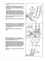
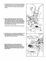
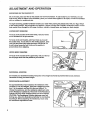
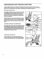
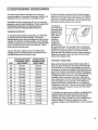
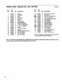
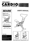
®
TOTAL BODY MOTION
SEARS
• LOW IMPACT
USER'S MANUAL
Model No. 831.287628
Serial No.
The serialnumbercan be found in the
locationshownbelow. Write the serial
numberin the space above.
I Number Decal
EXERCISE
EQ
u
i F'M
ENT
HELPLINE!
/-800.735-5879
CAUTION!
Read all precautions and
instructions In this manual
before using this equipment.
Keep this manu=l- for futu(e
reference.
PATENT PENDING
SEARS, ROEBUCK AND CO., HOFFMAN ESTATES, IL 60179
TABLE OF CONTENTS
IMPORTANT PRECAUTIONS ................................................................
BEFORE YOU BEGIN ............
-...........................................................
ASSEMBLY ...............................................................................
ADJUSTMENT AND OPERATION .................
............................................
MAINTENANCE AND TROUBLE-SHOOTING ....................................................
CONDITIONING GUIDELINES ................................................................
PART LIST ...............................................................................
EXPLODED DRAWING .....................................................................
ORDERING REPLACEMENT PARTS ..................................................
WARRANTY ......................................................................
2
3
3
6
8
9
10
11
Back Cover
Back Cover
IMPORTANT PRECAUTIONS
WARNING: To reduce the risk of serious injury, read the following important precautions before using the
SEARS ° LIFESTYLER CARDIO FIT.
1.
Use the CARDIO FIT only on a level surface.
2.
Wear appropriate clothing when exerclslng; do
not wear loose clothing that could become
caught In the CARDIO FIT. Always wear athletic
shoes for foot protection.
3. The CARDIO RT features a precision resistance
cylinder; due to the nature of resistance
cylinders, it is recommended that the floor
underneath the CARDIO FIT be covered in case
of slight oil leakage.
2
4.
Keep smell children away from the CARDIO FIT
at all times.
5. The resistance cyllnder becomes very hot
during use. Allow the reslstance cylinder to
cool before touching It. When adjusting the
resistance, touch only the resistance
adjustment collar.
6.
Use the CARDIO
manual.
FIT only as described
In this
WARNING: Before beginning this or any exercise program, consult your physician. This is especially
important for persons over the age of 35 or persons with pre-existing health problems, Read all
instructions before using. SEARS assumes no responsibility for personal injury or property damage
sustained by or through the use of this product.
BEFORE YOU BEGIN
Thank you for selecting the innovative SEARS®LIFE ;STYLER CARDIO FIT. The CARDIO FIT offers a
unique form of low-impact exercise that uses both the
upper body and lower body for increased
cardiovascular benefits and greater toning results.
For your benefit, read this manual carefully before
using the CARDIO FIT. If you have additional
questions, please call our toll-free HELPLINE at
1-800-736-6879, Monday through Saturday, 7 a.m.
until 7 p.m. Central Time(excluding holidays). To help
us assist you, please note the product model number
and serial number when calling. The model number is
831.287628. The sedal number can be found on a
decal attached to the CARDIO FIT (see the front cover
of this manual for the location of the decal).
ASSEMBLY
Place all parts of the CARDIO FIT in a cleared area and remove the packing materials. Do not dispose of the
packing materials until assembly is completed. Read each step carefully before beginning.
THE FOLLOWING TOOLS ARE REQUIRED FOR ASSEMBLY: The Included pedal tool (see the drawing
below), and your own phillips screwdriver
-.-----..-[_,
adjustable wrench _;_,
and rubber
mallet _.
PART CHART
Use the drawings below to identify the small parts used in assembly. The number in parenthesis below each
drawing refers to the key number of the part. The second number refers to the quantity used in assembly. Note:
Some small parts may have been pre-attached for shipping purposes. If a part is not found in the parts bag,
check to see if it has been pre-attached.
3/4" x 2" Pedal Tool--1
1/2" Dome Cap (29)--4
Note: One extraDome Cap
may have been included.
#8 x 1/2" Screw (16)_
Note: One extra #8 x 1/2" Screw
may have been included.
1/2" Push Nut (30)--2
1/2" Bushing (25)--2
3
1. Tap a 1/2" Bushing (25) into each side of the Frame (6)
as shown.
Apply grease to the Pivot Rod (21). Align the holes in
the Pedal Frame (7) with the indicated tube on the
Frame (6). Tap the Pivot Rod through the Pedal Frame
and the Frame.
i
IMPORTANT NOTE: Before assembling the 112"
Dome Caps (29), make sure that you thoroughly
understand the assembly step(s) they are used in.
They can be assembled only once. If they must be
removed, you will need to order new Dome Caps.
Center the Pivot Rod (21) and tap a 1/2" Dome Cap
(29) onto each end of it.
Make sure that the Magnet (27) is on the Pedal Frame
27
(7).
2. Make sure that there is a 1/2" Link Arm Bushing (19) in
the right Link Arm (4) (see the inset drawing). Slide the
Link Arm onto the indicated pin on the Pedal Frame
(7). Pivot the Pedal Frame and tap a 1/2" Dome Cap
(29) onto the pin.
Attach the left Link Arm (not shown) in the same
manner.
3. Make sure that there is a I 1/4" x 2" Endcap (13) on
each end of the Handlebar (2). The Endcaps must be
turned so the round ends are on top.
3
Slide the Handlebar (2) into the Pedal Frame (7). The
Handlebar must be turned so the sides bend toward
the Seat (not shown). Align the holes In the Handlebar
with the holes In the Pedal Frame. Attach one side of
the Handlebar with two #8 x 1/2" Screws (16). Attach
the other side of the Handlebar with two #8 x 112"
Screws.
t
Slide the I 1/4" x 2" Endsaps (13) down over the Pedal
Frame (7).
4
4. Connect the Sensor Wire (15) to the wire on the Monitor
(1). Insert any excess wire into the Frame (6). Attach the
Monitor to the Frame with a #8 x 1/2" Screw (16), Make
sure not to pinch the wire between the Frame and the
Monitor.
"'-- 6
5. Apply a small amount of grease to the shafts on the
lower end of the Pedal Frame (7). Slide a Pedal (12)
onto the dght shaft. Make sure that the indicated plastic
tube is facing the Pedal Frame. Using the included pedal
tool, tap a 1/2" Push Nut (30) onto the shaft. Make sure
that the Push Nut is turned so the teeth bend away from
the Pedal (see the inset drawing).
Grease
Attach the other Pedal (not shown) in the same manner.
i F')
Tube
,+
,+
Plastic
___
6
<_ 1_2/_307
P_ed
(Teeth
--30
6. Remove the two 114"x 2" Screws (17) attaching the Seat
(3) to the underside of the Seat Tube (5). Attach the
Seat, with the narrow end forward, to the top of the Seat
Tube with the two Screws as shown.
.. - "_-..._
al
Tool
Narrow End
7. Pivot the Pedal Frame (7) until the Magnet (27) is
aligned with the Reed Switch (15) (see the inset
drawing). Loosen the #8 x 3/4" Screw (18)o Slide the
Reed Switch toward the Magnet until thereto
is a 1/8" gap
between the Reed Switch and the Magnet. "13ghtenthe
#8 x 3/4" Screw.
5
ADJUSTMENT
AND OPERATION
EXERCISING ON THE CARDIO FIT
Sit on the seat, place your feet on the pedals and hold the handlebar. To add variety to your exercise, you can
hold the top, sides or bottom of the handlebar, place your hands close together or far apart, or hold the handlebar
with an overhand or underhand gdp.
To begin exemising, pull the handlebar towards your waist while pushing the pedals away with your legs. Return
to the starting position. This completes one repetition. Repeat, moving with a smooth, continuous motion. For the
best results, move through the full range of motion, maintain a steady pace, and keep your back straight.
LOWER BODY EXERCISE
To focus on the muscles of the lower body, rest your hands
on the indicated bar as you exercise.
To focus on the calf muscles, point your toes as you push
the pedals away. As you return to the starting position, raise
your toes and rotate your heels downward. CAUTION; To
avoid injury, keep you feet firmly on the pedals to
prevent them from sllppthg.
UPPER BODY EXERCISE
To focus on the muscles of the upper body, rest your feet on
the foot pegs rather than the pedals as you exercise.
Foot Peg
ABDOMINAL EXERCISE
To exercise your abdominal muscles, keep your arms straight and bend back at the waist as you exercise.
Remember to keep your back straight.
RESISTANCE ADJUSTMENT
To vary the intensity of your exercise, the resistance of the
CARDIO FIT can be changed. There are 9 resistance levels:
level 1 is the easiest, and level 9 is the most difficult.To
change the resistance, turn the resistance adjustment collar
on the Resistance Cylinder (9). The arrow on the Resistance
Cylinder will show which resistance level you have selected.
CAUTION. The Resistance Cylinder becomes very hot
during use. Allow the Resistance Cyllnder to cool before
touching It. When adjusting the resistance, touch only
the resistance adjustment collar.
6
DESCRIPTION
OF THE MONITOR
Note: The CARDIO FIT features one of the four monitors shown below. All four monitors have exactly the
same modes. The operation of the monitors is described below.
1
2
4
3
I F_II-1.I-II3
otCus_
./&qO.Off.
OOO
000
The monitor offers five modes to provide you with instant exercise feedback:
oSpeed--Displays your speed, in repetitions per minute.
• Time--Displays the length of time you have exercised. Note: If you stop exercising for ten seconds or longer,
the time mode will pause until you resume.
• Distance. Displays the total number of repetitions you have completed, up to 999. The display will then reset t°
zero and continue counting. (Monitor 2 above will display up to 9,999 repetitions.)
• Calories--Displays the approximate number of Calodes you have burned. Note: If the resistance is near the
highest or lowest setting, the actual number of Calodes you have burned will be slightly higher or lower than t.he
number displayed.
• Scan--Displays
"
all of the above modes, for approximately 5 seconds each, in a repeating cycle.
HOW TO OPERATE THE MONITOR
1. To turn on the power, press the on/off button or simply begin exercising on the CARDIO FiT. (If you have
monitor 2 above, press the on/reset button.) When the power is turned on the entire display will appear for two
seconds. The monitor will then be ready for operation.
2. Select one of the five modes:
Scan mode--When the power is turned on, the scan mode will be
selected automatically, One mode indicator will show that the scan
mode has been selected, and a second mode indicator will show
which mode is currently displayed. The scan mode can also be
selected by repeatedly pressing the mode button. (If you have
monitor 3 above, press the scan button).
Speed, time, distance or calodes mode--These modes can be
selected by repeatedly pressing the mode button. The mode
indicators will show which mode has been selected. The modes will be
Mode Indicators
D,_amco _
S=m
selected in the following order:,speed, time, distance, calories.
3. To reset the display, press the on/off button twice. (If you have monitor 2 above, press the on/reset button; if you
have monitor 4 above, press the clear button).
4. TO turn off the power, press the on/off button. (If you have monitor 2 above, there is no on/off button. Simply
walt for about four minutes for the "auto-off" feature to turn off the power.) Note: All four monitors have an "autooff" feature. If the pedals are not moved and the monitor buttons are not pressed for four minutes, the power will
turn off automatically in order to conserve the batteries.
7
MAINTENANCE
AND TROUBLE-SHOOTING
Inspect and tighten all parts of the CARDIO FIT at least every three months. Keep the monitor out of direct
sunlight or the LCD display may be damaged. The monitor can be cleaned using a soft, dry cloth. Do not allow
liquid to come in contact with the monitor• Remove the batteries when storingthe CARDIO FIT.
REPLACING THE BATI'ERIES
if the display of the Monitor (1) becomes dim, the two Ll154
watch batteries should be replaced. Remove the #8 x 1/2"
Screw (16) from the back of the Monitor. Remove the two
screws from the back cover of the Monitor and remove the
back cover. Push the two old batteries out of the clips, and
insed two new batteries,
Reattech the back cover and reattach the Monitor (1) to the
Frame (6). Make sure that the wire on the Monitor is plugged
into the sensor wire. Insed any excess wire into the Frame.
Make sure not to pinch the wire between the Frame and the
Monitor.
ADJUSTING THE MAGNET AND REED SWITCH
If the monitor does not function propedy, the Magnet (27) and
Reed Switch (15) should be checked. Pivot the Pedal Frame
(7) until the Magnet is aligned with the Reed Switch. Loosen
the #8 x 3/4" Screw (18) and slide the Reed Switch toward
the Magnet until there is a 1/8" gap between the Magnet and
the Reed Switch. Retighten the Screw.
LUBRICATING THE CARDIO FIT
Apply Oil
The ends of the Link Arms (4) should be oiled every six
months. Apply a few drops of light multi-purpose oil between
the Unk Arms and the dome caps in the indica.tedlocations.
8
CONDITIONING
GUIDELINES
The following guidelines will help you to plan your
exercise program. Remember that proper nutrition and
adequate rest are essential for successful results.
WARNING" Before beginning this or any exercise
program, consult your physician. This Is especially
important for persons over the age of 35 or
persons with pre-exlsttng health problems.
EXERCISEINTENSITY
To maximize the benefits of exercising, it is important
to exercise with the proper intensity. The proper
intensity level can be found by using your heart rate as
a guide. For effective aerobic exercise, your heart rate
should be maintained at a level between 70% and 85%
of your maximum heart rate as you exercise. This is
known as your training zone.
You can find your training zone in the table below.
Training zones are listed for both unconditioned and
conditioned persons according to age.
UNCONDITIONED
TRAINING ZONE
CONDITIONED
TRAINING ZONE
AGE
(BEATS/MIN)
(BEATS/MIN)
20
138-167
133-162
25
136-166
132-160
30
135-164
130-158
35
134-162
129-156
40
132-161
127-_155
45
131-159
125-153
50
129-156
124-150
55
127-155
122-149
60
126-153
121-147
65
125-151
119-145
70
123-150
118-144
75
122-147
117-142
80
120-146
115-140
85
118-144
114-139
During the first few months of your exercise program,
keep your heart rate near the low end of your training
zone as you exercise. After a few months, your heart
rate can be increased gradually until it is near the middle of your training zone as you exercise.
To measure
your heart rate,
stop exercising
and place two
fingers on your
wrist. Take a
six-second
heartbeat
count, and
multiply the
result by 10 to
find your heart rate. For example, if your six-second
heartbeat count is 14, your heart rate is 140 beats per
minute. (A six-second count is used because your
head rate will drop rapidly when you stop exercising.)
Adjust the intensity of your exercise until your heart
rate is at the proper level.
WORKOUT GUIDELINES
Each workout should consist of three basic pads: a
warm-up, 20 to 30 minutes of training zone exemise,
and a cool-down. Warming up prepares the body for
exercise by increasing circulation, delivering more oxygen to the muscles and raising the body temperature.
Begin each workout with 5 to 10 minutes of stretching
and light exercise to warm up. Then, increase the
intensity of your exercise to raise your head rate to
your training zone for 20 to 30 minutes. Breathe regularly and deeply as you exercise-never
hold your
breath. Finish each workout with 5 to 10 minutes of
stretching to cool down. This will increase the flexibility
of the muscles, and reduce soreness and other postexercise problems.
To maintain or improve your condition, complete three
workouts each week, with at least one day of rest
between workouts. After a few months of regular
exercise, you may complete up to five workouts each
week, if desired. The key to success is to make
exercise a regular and enjoyable part of your everyday
life.
9
PART LIST--Model
No. 831.287628
Key
No.
Part
No.
Qty.
1
2
3
4
5
6
117523
117529
117511
117528
117525
123690
1
1
1
2
1
1
Monitor
Handlebar
Seat
UnkArm
Seat Tube
Frame
7
8
9
10
11
12
13
14
15
16
17
18
122379
109416
117555
117545
117544
124807
125390
122296
124434
013162
013498
013300
1
4
1
2
1
2
2
1
1
5*
2
1
pedal Frame
Round Endcap
Resistance Cylinder
1 1/4"xl 114"Endcap
t 1!2"x2"Endcap
Pedal
1 l/4"x2"Endcap
Bumper
Reed Switch/Sensor Wire
#8 x 1/2" Screw
114"x 2" Screw
#8 x 3/4" Screw
Description
R0995A
Key
No.
Part
No.
Qty.
19
20
103677
117509
117552
109470
106876
117510
4
2
1
1
2
2
_
_
23
24
_
110576
2
26
118904
2
27
113349 . 1
28
124260
1
/_103903
10"
30
012155
2
31
118213
1
32
124546
4
#
123702
1
#
118061
1
Description
1/2" LinkArm Bushing
3/8" Spacer
1/2"xll
114" Pivot Rod
1/2" x3 1/2" Rod
1/2" Cylinder Bushing Set
15/16"Spacer
1/2" Bushing
Foot Peg Foam
Magnet/Retainer
1!2" x 61!2" Rod
1!2" Dcme Cap
1/2" Push Nut
1/2"x4"Rod
1/2" Plastic Bushing
User's Manual
314" x 1" Pedal Tool
*Note: One extra #8 x 1/2" Screw and one extra 112"
Dome Cap may have been included.
Note: "#" indicates a non-illustrated pad. Specifications are subject to change without notice. See the back cover
of this manual for information about ordedng replacement parts.
lo
EXPLODED
DRAWINGmModel
No. 831.287628
n099sA
3
7
11
8
s
s
s
.s
s
s
8
11
SEARS
The model number and serial number of your SEARS LIFESTYLER °
CARDIO FIT are listed on a decal attached to the frame. See the
front cover of this manual to find the location of the decal.
Model No. 831.287628
All replacement parts are available for immediate purchase or
special order when you visit your nearest SEARS Service Center. To
request service or to order pads by telephone, call the toll-free
numbers listed at the left.
QUESTIONS?
If you find that:
• you need help assembling or
operating the LIFESTYLER
CARDIO FIT
When requesting help or service, or ordering pads, please be
prepared to provide the following information:
• a part Is missing
• The NAME OF THE PRODUCT (SEARS LIFESTYLER e CARDIO
FIT)
• or you need to schedule repair
service
call our toll-free HELPLINE
• The MODEL NUMBER OF THE PRODUCT (831.287628)
• The PART NUMBER OF THE PART (see page 10 of this manual)
1-800-736-6879
Monday-Saturday, 7 am-7 pm
Central Time (excluding holidays)
• The DESCRIPTION OF THE PART (see page 10 of this manual)
REPLACEMENT PARTS
ff parts become worn and need
to be replaced, call the following
toll-free number
1-800-FON-PART
(1-800-366-7278)
I
FULL 90 DAY WARRANTY
I
For 90 days from the date of purchase, if failure occurs due to defect in material or workmanship in this
SEARS CARDIO FIT EXERCISER, contact the nearest SEARS store throughout the United States and
SEARS will repair or replace the CARDIO FIT EXERCISER, free of charge.
This warranty does not apply when the CARDIO FIT EXERCISER Is used commerciallyor for rental
purposes.
This warranty gives you specific legal rights, and you may also have other rights which vary from state
to state.
SEARS, ROEBUCK AND CO., DEPT. 817WA, HOFFMAN ESTATES, IL 60179
Part No.127605 R0995A © 1995 Seam, Roebuck and Co.
Printed in USA