1
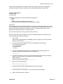
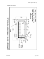
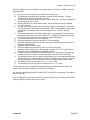
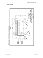
Module 3 (former YD 1.2/3)
LESSON THIRTY
Introduction
To
Computer-Aided Boat Design (CAD)
Lesson Overview and Objectives:
This lesson is intended to introduce students to the hardware and software that is need to
perform computer-aided design or “CAD.” It describes the design tasks that are performed by
the boat designer on a personal computer using commercially available software. This
information will help guide you in using CAD in boat design.
After completing this lesson, you will be able to:
a. Describe the basic hardware components (the complete computer system) needed for
CAD.
b. Describe which programs are used for CAD in boat design and for what purpose.
c. Describe the general sequence of steps and processes used to design a boat employing
CAD.
d. Understand and discuss basic concepts in practical applications using AutoCad.
e. Draw a basic CAD detail drawing to precise CAD-drawing specifications.
NOTE: This lesson is a bit different. It does not have to be submitted in sequence as do
other lessons. If you have been working on CAD and wish to do this lesson earlier (out
of sequence) in Module 3, you may. You may also wish to start this lesson early and
submit it, for preliminary review only, early in Module 3. You can then continue to work
on this lesson (lesson 30) as you work on other lessons in Module 3 and improve your
CAD skills.
You must complete this lesson before submitting lesson 31, which must be done in
CAD.
Study Assignment:
1. Study the Student Guide 2nd Edition (the SG2), sections 2.1 through 2.6, pages 28 through
50. (If you have the old Westlawn text Book 125, “Overview of Computer Aided Yacht Design &
Lesson 30
Page 30-1
Module 3 (former YD 1.2/3)
Construction,” please do NOT refer to this text for this assignment as it is out of date and no
longer being used.)
2. Be sure to check the Westlawn Student Forum for the latest updates to the SG2. Review and
study your copy of “AutoCad No Experience Required.” Have your AutoCad user’s manual
available for reference.
3. Review the section on Computer Aided Yacht Design in Westlawn book 108, in Module 1,
starting on page 66. Even better—since computer programs are always being updated—go to
http://newavesys.com/tutorial.htm, to download the latest version of these tutorials. If you are
using another hull-fairing program (other than ProSurf) then review their tutorials.
Written Assignment:
Lesson 30 – Question Paper
After studying the pages 28 through 50 in the SG2 for this lesson, complete the written and
CAD assignment and send your work to the school for grading.
Instructor’s Notes:
If you have not already begun your practice in CAD, remember that it is school policy that all
lessons—from lesson 31 on—be submitted in CAD. You should have obtained a copy of the
book “AutoCad No Experience Required,” by David Frey, published by Sybex (for the version of
AutoCad you are using) while you were in Module 1, and should have been working through
the exercises in this book for several months now—as explained in the SG2.
It is also recommended that you get a copy of the Mastering AutoCad Series, by Omura,
published by Sybex .
You should have a copy of your AutoCad user’s manual available for reference.
AutoCad Hints:
To set the text in the dimensions you first have to create a Text Style. If you’re setting up the
0.5-inch-high Arial text, for example, you’d go to the Format menu, then to the Text Style dialog.
Click on the “New” button, and give this new text-style a clear name such as “0.5arial”. Usually,
you would leave “Big Font” checked, for most standard AutoCad fonts, but Arial (and Times
New Roman) are Windows TrueType fonts (to be sure everyone has access to the same fonts
for this lesson.) For this reason, uncheck “Use Big Font.” Select “Arial,” select style “regular,”
and set the height at 0.5 inches. Close out and you’ve created your text style.
In a regular AutoCad drawing, you’d set up several text styles of different sizes to use with
different plot scales. Other text styles would be for note blocks, title blocks, etc.
Now, you need to go to create the dimension style to use this Text Style with the arrow and
other specs required by Big Bay Boats (see the assignment below). From the Formant Menu go
to Dimensions Styles. Click on New. Go to the Text tab and select the text color and set the text
height. Where you see Text Style, click on the arrow and scroll down to select the Text Style
you just created. Finish selecting the other dimension features you need to duplicate the
dimensions in the example drawing. You’ll use the Lines and Arrows Tab, the Text Tab, the Fit
Tab, and the Primary Units Tab. Refer also to your AutoCad Manual and to “AutoCad No
Experience Required.” (Note: Changing the text height in this dialog won’t change the height
from the 0.5 inches you set in your Text Style. If you want 0.75-inch-high text, you have to go
back and create a new Text Style for this height in the Text Style menu, then return to the
Lesson 30
Page 30-2
Module 3 (former YD 1.2/3)
Dimension Style and create a new Dimension Style for this new height, as you did for the 0.5inch text.)
To control and set up layers you can go to the Format menu and the to Layer, or you can just
type keyboard command “la” then enter.
You are free to create the geometry using any method that you prefer; however, the fastest way
to create the outside rectangle of the portlight, is probably not to use the rectangle tool and then
explode it or (alternately) to draw a series of connected lines using the line tool, but rather to
use construction lines—horizontal and vertical, and the Offset command. You can throw
construction lines down quickly with keyboard commands. In this case, you’d do the following:
The keyboard command for a horizontal construction line is “xlh” and is “xlv” for vertical
construction lines. (“xla” enter lets you put down a construction line at any angle you then
specify). Set the “portlight” layer as current, and type “xlh” and enter, and click on where you
want the line to go. Now, offset that line up or down by the height of the portlight. Do “o,” enter,
“7.75” (the height in inches) enter, then click on the construction line and then above or below it
to offset.
Remember that the space bar acts as the “enter” key in AutoCad, so—using keyboard
commands—you can pretty much keep one hand on the mouse and one hand on the keyboard.
Mastering this will allow you to draw very quickly in AutoCad.
Hit escape to end the offset command and then put in a vertical construction line and offset that
using the methods you used to create the horizontal lines. Use the fillet (with radius) command
to finish off the outside perimeter corners of the portlight.
Use the offset command to build in the inner rings of the portlight frame.
Finish up by drawing the hinges and dogs using the appropriate AutoCad tools.
To hatch the drop-shadow hatch and the secondary shadow both need hatachable boundaries.
Simply copy the upper and left edges of the inside window ring and drag them down and to the
right until they’re in the proper location to give you the desired hatch areas. Trim the stray ends
off after this copying process. Using the properties dialog move these hatch borders to the
“hatch” layer.
Now, switch the “hatch” layer to current, and add the solid drop-shadow hatch and the
secondary shadow hatch. Delete the boundary for the secondary shadow hatch once it’s
completed. The hatch itself will remain.
Now add the dimensions (create your dimensions in model space NOT in paper space) and
finish up the title block and border in paper space, after creating the viewport you need at the
proper scale and location. Refer to the SG2 page 45 about setting up viewports in paper space,
and to “AutoCad No Experience Required.”
Continue to adjust and experiment until you have duplicated the drawings as exactly as
possible.
Note: You can see that setting up Text and Dimension Styles is a bit cumbersome. Once you’ve
mastered these, you should set up a complete set of Text Styles and Dimension Styles for a
complete set of plot scales. Also set up a standard border and title block in model space, set
your default lineweight, and some standard layers—“workinglayer1, “workinglayer2,”
“dimension,” “hatch,” etc. Now, save this file as a Drawing Template File (a .dwt file). All your
Lesson 30
Page 30-3
Module 3 (former YD 1.2/3)
setting will be saved and you won’t have to redo them every time you start a new design or
drawing in AutoCad. Read your AutoCad user’s manual about Drawing Template Files.
Lesson 30 Assignment
Question Paper
(19) Questions
Materials and equipment needed to complete this assignment:
* paper
* pencil
* computer and word processor (Word or equal)
* a working version of AutoCad or AutoCad Lite 2000, or higher
Instructions:
Use any paper or your word processor (Excel) for your reply. Use as many sheets as you wish.
For the AutoCad drawing, email the CAD file in .dwg format. (Non AutoCad users may use .dxf
format.) Alternately, you may burn the CAD file to a CD or a floppy disk and mail it in. We
MUST receive the CAD file itself, not a paper print-out.
Do make a hard-copy print-out for yourself to check your work.
Refer to the Student Guide 2nd Edition and to the Orientation/Information for instructions on
sheet headings and numbering questions.
1.
True or false
When doing a CAD drawing it is acceptable to finish up a print-out or plot with manual
drafting or hand drawing _______________
2.
How many buttock lines should be drawn on a standard hull-line drawing?
How should they be spaced:
a. at critical locations
b. as convenient
c. equally
3.
How many waterlines should be used on a standard hull-lines drawing above the
waterline—between the DWL and the sheer at station 5?
____________
4.
If a boat has a beam of 12 feet (3.6 m) and a freeboard (height from DWL to sheer) at
station 5 of 40 inches (102 cm). What would you recommend as:
Buttock spacing _____________
Waterline spacing above the DWL _____________
5.
Name two hull-faring programs.
a. ________________________
b. ________________________
6.
Name the common surface-modeling program used in the industry.
________________________
7.
Why is AutoCad recommended for use in doing your working drawings?
8.
What is GHS and what is it used for?
Lesson 30
Page 30-4
Module 3 (former YD 1.2/3)
9.
As of May 2004, describe the components of a basic standard CAD computer package
required for boat-design work.
10. How should units be set up in your AutoCad drawing?
11. What scale do you draw in in model space in AutoCad?
12. List and describe the process of creating a paper space view of your drawing in model
space.
13. In a few paragraphs, clearly describe the standard basic sequence of steps for doing a
boat design in CAD.
14. If you have an existing object drawn in AutoCad and want first to find out what layer it is
on and what lineweight it is drawn in, then change these characteristics, what one dialog
box or feature do you use?
15. a. What is “linetype scale?”
b. How do you change linetype scale from 1.0 to 12?
16. What does the “list” command tell you?
17. a. What aspects of layers zero (0), are different than other layers?
b. Should you draw your design on layer zero, yes or no?
18. a. If you have a polyline that is a dotted line, but the dots appear irregular, what causes
this?
b. What command do you use to correct this and make the polyline dot spacing appear
consistent?
c. If you want the dot spacing to be larger once you’ve made the dot spacing appear
consistent, what property of the polyline would you change?
19. You have been hired by the design department of Big Bay Boats. The chief designer has
assigned you to draw a detail of a portlight (opening window) for Big Bay Boats’ new
model. You must draw the detail to Big Bay Boats’ CAD standard, as follows:
In AutoCad, in model space, draw the portlight (opening window) below and meet the
following criteria exactly. (This is almost the same window detail that you drew manually
in lesson 10, question 18).
Note. The English-unit and metric versions are similar, but they are not exactly the same. Draw
either the English or metric version as you prefer. DO NOT DO BOTH
Lesson 30
Page 30-5
Module 3 (former YD 1.2/3)
ENGLISH-UNIT VERSION:
Lesson 30
Page 30-6
Module 3 (former YD 1.2/3)
Draw the portlight as close to exactly like the drawing above as you can. In addition, meet the
following criteria:
a)
b)
c)
d)
e)
f)
g)
h)
i)
j)
k)
l)
m)
n)
o)
p)
Be sure to set your drawing units to inches in the format menu.
The drawing of the portlight itself should be on a layer named “portlight.” The layer
should be set for 0.30 mm lineweight, color 140.
The dimensions should be drawn on a layer named “dimension.” The layer should be set
for lineweight 0.20 mm, color 9.
Hatching should be on a layer named “hatch.” The layer should be set for lineweight
0.13 mm, color 251.
The dark, solid shadow hatch under the window is called a “drop shadow.” This should
be on the hatch layer and should be hatch pattern “solid.” The secondary shadow hatch
also should be on the hatch layer. It should be pattern “line,” scale 4.0, angle 90
degrees.
The border and title block should be in paper space, not model space. The border and
title block should be on a layer named “titleblock,.” lineweight set for default (set default
for 0.25 mm), color white (which prints black on a white background).
The border should be set for 1.0 mm lineweight.
Dimension extension lines should be set for 0.13 mm lineweight
Dimension lettering height should be set to 0.5 inches, with stacked fractions at 70% of
dimension lettering height.
Dimension text font should be Ariel
Dimension leader lines should have “open” arrows 0.4 inches long.
Dimension units should be set to “Architectural,” precision 0’-0 1/16”,” Fraction format
“Diagonal” DO ALL DIMENSIONING IN MODEL SPACE.
The title block text font should be Times New Roman. The text height of “Portlight” (the
heading) should be 0.2 inches, and the remaining text should be 0.15 inches high.
The drawing should be set up to plot from paper space (not from a border and title block
in model space). The viewport should be created on a layer named “viewport,” color red.
This layer should be turned off (not frozen) when you finished setting up the drawing.
The drawing must be set up to plot a 3 in. = 1 ft. – 0 in. scale.
The drawing must be set up to plot on letter-size (8-1/2” x 11”) paper.
You may have to refer to “AutoCad No Experience Required” about Dimension Styles, Text
Styles, Layers and Layer Settings, and Paper Space Viewports.
Do not include the [ENGLISH UNITS – PRINT NOT TO SCALE] in your drawing. Your drawing
should be to scale.
Note. The English-unit and metric versions are similar, but they are not exactly the same. Draw
either the English or metric version as you prefer.
Lesson 30
Page 30-7
Module 3 (former YD 1.2/3)
METRIC VERSION:
Lesson 30
Page 30-8
Module 3 (former YD 1.2/3)
Draw the portlight as close to exactly like the drawing above as you can. In addition, meet the
following criteria:
a)
b)
c)
d)
e)
f)
g)
h)
i)
j)
k)
l)
m)
m)
o)
p)
Be sure to set your drawing units to mm in the format menu.
The drawing of the portlight itself should be on a layer named “portlight.” The layer
should be set for 0.30 mm lineweight, color 140.
The dimensions should be drawn on a layer named “dimension.” The layer should be set
for lineweight 0.20 mm, color 9.
Hatching should be on a layer named “hatch.” The layer should be set for lineweight
0.13 mm, color 251.
The dark, solid shadow hatch under the window is called a “drop shadow.” This should
be on the hatch layer and should be hatch pattern “solid.” The secondary shadow hatch
also should be on the hatch layer. It should be pattern “line,” scale 100, angle 90
degrees.
The border and title block should be in paper space, not model space. The border and
title block should be on a layer named “titleblock,.” lineweight set for default (set default
for 0.25 mm), color white (which prints black on a white background).
The border should be set for 1.0 mm lineweight.
Dimension extension lines should be set for 0.13 mm lineweight
Dimension lettering height should be set to 12 mm.
Dimension text font should be Ariel
Dimension leader lines should have “open” arrows 10 mm long.
Dimension units should be set for “Decimal,” precision “0.”
The title block text font should be Times New Roman. The text height of “Portlight” (the
heading) should be 3.75 mm, and the remaining text should be 3.0 mm high. DO ALL
DIMENSIONING IN MODEL SPACE.
The drawing should be set up to plot from paper space (not from a border and title block
in model space). The viewport should be created on a layer named “viewport,” color red.
This layer should be turned off (not frozen) when you finished setting up the drawing.
The drawing must be set up to plot a 1:5 scale.
The drawing must be set up to plot on A4 (210 x 297 mm) paper.
You may have to refer to “AutoCad No Experience Required” about Dimension Styles, Text
Styles, Layers and Layer Settings, and Paper Space Viewports.
Do not include the [METRIC – PRINT NOT TO SCALE] in your drawing. Your drawing should
be to scale.
Note. The English-unit and metric versions are very similar, but they are not exactly the same.
Draw either the English or metric version as you prefer.
Lesson 30
Page 30-9