1
Table of Contents
1
Installing DynaSCAPE Design
1.1
How to Use This Manual...................................................................... 1.2
Typographical Conventions .................................................................. 1.2
Other Terminology............................................................................ 1.3
Installation of DynaSCAPE Design . . . . . . . . . . . . . . . . . . . . . . . . . . . . . . 1.4
Installation Overview......................................................................... 1.4
System Requirements ........................................................................ 1.4
Required Skills................................................................................. 1.5
Pre-Installation Checklist .................................................................... 1.6
Checking for Internet Updates . . . . . . . . . . . . . . . . . . . . . . . . . . . . . . . .1.11
Uninstalling DynaSCAPE Design . . . . . . . . . . . . . . . . . . . . . . . . . . . . . . . .1.12
2
Getting Started
2.1
Starting DynaSCAPE Design. . . . . . . . . . . . . . . . . . . . . . . . . . . . . . . . . . . 2.2
Starting the DynaSCAPE Design Program .................................................. 2.2
Software Activation .......................................................................... 2.2
When DynaSCAPE Design Opens for the First Time ...................................... 2.3
What is a Prototype Drawing? . . . . . . . . . . . . . . . . . . . . . . . . . . . . . . . . . 2.4
Opening a Prototype Drawing (Template) ................................................ 2.4
Understanding Prototype Drawing Names................................................. 2.5
How to Choose a Prototype Drawing....................................................... 2.5
Main Features of the DynaSCAPE Interface —Overview. . . . . . . . . . . . . . . . 2.7
Working with Toolboxes ..................................................................... 2.7
Opening, Closing, and Minimizing Toolboxes ............................................. 2.8
Switching Between (Rolling-Over) Toolboxes............................................. 2.9
Resizing Toolboxes............................................................................ 2.9
Opening Nested Tools .......................................................................2.11
TABLE
OF
CONTENTS
1
DynaSCAPE Design (Version 6.4)
Working with Panels . . . . . . . . . . . . . . . . . . . . . . . . . . . . . . . . . . . . . . . 2.14
Modifier Panels .............................................................................. 2.14
Visibility Toggles ............................................................................ 2.15
The Program Titlebar ....................................................................... 2.19
The Prompt Line ............................................................................. 2.19
Command Line Interpreter (CLI) .......................................................... 2.20
A Tour of the Button Bars . . . . . . . . . . . . . . . . . . . . . . . . . . . . . . . . . . . 2.22
The Top Button Bar ......................................................................... 2.22
The Toggle Bar............................................................................... 2.23
Inference Settings ........................................................................... 2.24
The Copy Toggle ............................................................................. 2.26
The Sidebar Folders ......................................................................... 2.26
The DynaSCAPE Sidebar Folder . . . . . . . . . . . . . . . . . . . . . . . . . . . . . . . 2.28
Tables and Modes Controls................................................................. 2.30
The Select and Revise Toggles ............................................................ 2.31
Editing the Active List ...................................................................... 2.32
The Figures Sidebar Folder ................................................................ 2.32
The Favorites Sidebar Folder .............................................................. 2.34
The Imaging Sidebar Folder................................................................ 2.35
Drawing Navigation . . . . . . . . . . . . . . . . . . . . . . . . . . . . . . . . . . . . . . . 2.37
Zooming Using the Mouse Wheel .......................................................... 2.37
Panning Using the Mouse Wheel........................................................... 2.37
The other Zoom Tools ...................................................................... 2.38
Opening and Saving a Drawing Exercise: ................................................ 2.41
How to Save a Drawing ..................................................................... 2.41
Saving Over a Network Not Recommended.............................................. 2.42
Saving to a Removable Storage Device is Unsafe....................................... 2.42
Saving a Drawing Manually ................................................................. 2.42
Saving a Drawing Automatically: The Autosave Command............................ 2.44
How to Close a Drawing .................................................................... 2.45
Exiting DynaSCAPE Design.................................................................. 2.46
TABLE OF CONTENTS
2
DynaSCAPE Software
Table of Contents
3
Opening a DynaSCAPE Drawing
3.1
Opening a DynaSCAPE Drawing . . . . . . . . . . . . . . . . . . . . . . . . . . . . . . . . 3.2
Opening a DynaSCAPE Design Sample Drawing ........................................... 3.2
Working with Multiple Drawings ............................................................ 3.3
Opening a Version 2.0/2.5 (Legacy) Drawing or Project Bundle. . . . . . . . . . 3.4
If Your Drawing Will Not Open .............................................................. 3.5
Deleting Unneeded Project Management Files ........................................... 3.5
Converting a 4.x Drawing to 5.x or Newer . . . . . . . . . . . . . . . . . . . . . . . . 3.7
How Do I Know if My Drawing is Version 4.x or Version 5.x and Newer? ............. 3.7
Can I Convert a Pre-Version 4.x Drawing to 5.x or Newer?............................. 3.8
Why Do I Need to Convert my Drawings to 5.x or Newer? .............................. 3.8
How to Convert a Drawing to 5.x and Newer Format ................................... 3.9
Limitations of Converted Drawings........................................................3.10
File Management . . . . . . . . . . . . . . . . . . . . . . . . . . . . . . . . . . . . . . . . .3.12
How DynaSCAPE File Management Differs from Older Versions ......................3.12
Resetting Windows Explorer to Show File Extensions ..................................3.13
Backing Up and Protecting Your Work ....................................................3.15
Program Resources . . . . . . . . . . . . . . . . . . . . . . . . . . . . . . . . . . . . . . . .3.16
Additional Resources ........................................................................3.16
4
Menus, Settings and Controls
4.1
Pull-Down Menus . . . . . . . . . . . . . . . . . . . . . . . . . . . . . . . . . . . . . . . . . 4.2
The Environment Menu . . . . . . . . . . . . . . . . . . . . . . . . . . . . . . . . . . . . . 4.3
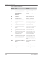
System Settings ............................................................................... 4.4
Command Aliases and Keyboard Shortcuts................................................ 4.5
The Drawing Page Settings .................................................................. 4.9
TABLE
OF
CONTENTS
3
DynaSCAPE Design (Version 6.4)
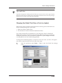
Viewing and Editing the Data Format Settings.......................................... 4.11
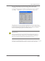
Grid, Axis and Snap Tool Settings......................................................... 4.13
Background Color of the Drawing Page .................................................. 4.15
Inference Settings . . . . . . . . . . . . . . . . . . . . . . . . . . . . . . . . . . . . . . . . 4.18
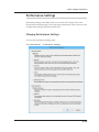
Performance Settings . . . . . . . . . . . . . . . . . . . . . . . . . . . . . . . . . . . . . . 4.23
Changing Performance Settings ........................................................... 4.23
The Entity Menu . . . . . . . . . . . . . . . . . . . . . . . . . . . . . . . . . . . . . . . . . 4.24
Changing Global Text Settings ............................................................ 4.24
Changing the Global Text Size or Font (no leader) .................................... 4.25
Changing Label Text Settings (Dimension Text) ........................................ 4.26
Changing Leader Settings .................................................................. 4.29
The Tools Menu . . . . . . . . . . . . . . . . . . . . . . . . . . . . . . . . . . . . . . . . . . 4.33
The Data Selection Panel .................................................................. 4.33
The Coordinate Tracking Panel ........................................................... 4.34
The Overview Panel......................................................................... 4.35
Instream Commands ........................................................................ 4.35
The Windows Menu . . . . . . . . . . . . . . . . . . . . . . . . . . . . . . . . . . . . . . . 4.37
Content Help . . . . . . . . . . . . . . . . . . . . . . . . . . . . . . . . . . . . . . . . . . . . 4.38
5
Using the Tables
5.1
Tables Overview . . . . . . . . . . . . . . . . . . . . . . . . . . . . . . . . . . . . . . . . . . 5.2
Layers and Screen Colors.....................................................................5.2
Layers and Modes..............................................................................5.2
Layers . . . . . . . . . . . . . . . . . . . . . . . . . . . . . . . . . . . . . . . . . . . . . . . . . 5.3
The Importance of Layers ....................................................................5.3
The Layer Table Editor .......................................................................5.5
Line Styles . . . . . . . . . . . . . . . . . . . . . . . . . . . . . . . . . . . . . . . . . . . . . . 5.6
TABLE OF CONTENTS
4
DynaSCAPE Software
Table of Contents
Creating New Line Styles .................................................................... 5.6
Line Weights . . . . . . . . . . . . . . . . . . . . . . . . . . . . . . . . . . . . . . . . . . . . 5.8
The Line Weight Table Editor ............................................................... 5.8
Fonts . . . . . . . . . . . . . . . . . . . . . . . . . . . . . . . . . . . . . . . . . . . . . . . . .5.10
Display Colors . . . . . . . . . . . . . . . . . . . . . . . . . . . . . . . . . . . . . . . . . . .5.11
Editing the Color List ........................................................................5.11
Modes . . . . . . . . . . . . . . . . . . . . . . . . . . . . . . . . . . . . . . . . . . . . . . . . .5.13
How Modes Work .............................................................................5.13
When to Use Modes ..........................................................................5.14
The Drawing Mode Selector ................................................................5.14
Display Modes—Multi-Layer .................................................................5.14
Display Modes—Single Layer ................................................................5.16
Editing Modes.................................................................................5.16
Why Drawings Can “Go Blank” .............................................................5.17
6
Basic Drawing Tools
6.1
Modifier Panels and Calculators . . . . . . . . . . . . . . . . . . . . . . . . . . . . . . . 6.2
The Draw [Creation] Toolbox . . . . . . . . . . . . . . . . . . . . . . . . . . . . . . . . . 6.4
Drawing Lines . . . . . . . . . . . . . . . . . . . . . . . . . . . . . . . . . . . . . . . . . . . 6.5
Draw a Line .................................................................................... 6.6
The Coordinate Tracking Panel ............................................................. 6.7
Using Bearings (and DMS) to Draw Property Lines ....................................... 6.8
Draw a Horizontal Line......................................................................6.10
Draw a Vertical Line.........................................................................6.11
Draw a Line Vertically or Horizontally Snapped.........................................6.12
Draw a Line Parallel to Another Line .....................................................6.13
Draw a Line Perpendicular to Another Line..............................................6.14
Draw a Line Tangent to Two Arcs .........................................................6.15
TABLE
OF
CONTENTS
5
DynaSCAPE Design (Version 6.4)
Draw a Line Tangent to an Arc ............................................................ 6.16
The Building Outline Tool . . . . . . . . . . . . . . . . . . . . . . . . . . . . . . . . . . . 6.18
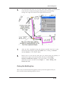
Why Building Outlines are Drawn this way .............................................. 6.19
How to use the Building Outline Tool .................................................... 6.20
Using the Snap Lines Orthographically Option .......................................... 6.22
Closing the Building Line ................................................................... 6.23
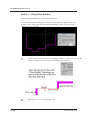
Option 1 - Using Close Outline: ........................................................... 6.24
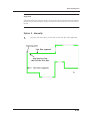
Option 2 - Manually: ........................................................................ 6.25
Drawing Polylines. . . . . . . . . . . . . . . . . . . . . . . . . . . . . . . . . . . . . . . . . 6.28
The Polyline Tool ............................................................................ 6.28
Drawing a Smooth (curved) Polyline: .................................................... 6.29
Additional Polyline Tools ................................................................... 6.32
Drawing Rectangles . . . . . . . . . . . . . . . . . . . . . . . . . . . . . . . . . . . . . . . 6.34
Drawing Polygons . . . . . . . . . . . . . . . . . . . . . . . . . . . . . . . . . . . . . . . . . 6.36
Drawing Arcs . . . . . . . . . . . . . . . . . . . . . . . . . . . . . . . . . . . . . . . . . . . . 6.39
Insert an Arc Between Two Locations Defining the Chord ............................ 6.39
Insert an Arc ................................................................................. 6.40
Insert an Arc Between Two Locations .................................................... 6.41
Insert an Arc Through Three Locations .................................................. 6.41
Insert an Arc Tangent to Two Locations ................................................. 6.42
Insert an Arc Using an Outside Tangent to an Entity .................................. 6.43
Using Bearings (and DMS) to Draw Property Line with Arcs........................... 6.43
Drawing Circles . . . . . . . . . . . . . . . . . . . . . . . . . . . . . . . . . . . . . . . . . . 6.48
Insert a Corner Radius . . . . . . . . . . . . . . . . . . . . . . . . . . . . . . . . . . . . . 6.49
Hatch and Generic Patterns. . . . . . . . . . . . . . . . . . . . . . . . . . . . . . . . . . 6.51
Inserting Generic Patterns (Sections) .................................................... 6.51
Hatch Pattern Tools......................................................................... 6.53
Using the Hatch and Generic Pattern Tools ............................................. 6.55
Drawing Ellipses. . . . . . . . . . . . . . . . . . . . . . . . . . . . . . . . . . . . . . . . . . 6.60
Drawing an Ellipse........................................................................... 6.60
Drawing an Elliptical Arc ................................................................... 6.61
TABLE OF CONTENTS
6
DynaSCAPE Software
Table of Contents
7
Basic Editing and Dimensioning Tools 7.1
The Edit Toolbox . . . . . . . . . . . . . . . . . . . . . . . . . . . . . . . . . . . . . . . . . 7.2
Moving and Copying Objects ................................................................ 7.2
Offset or Move Lines by an Absolute Parallel Distance ................................. 7.4
Resizing Objects by Scale Ratio ............................................................ 7.6
Mirroring Objects Across a Location ....................................................... 7.8
Exploding Objects into Individual Lines and Arcs ........................................ 7.9
Rotating Objects .............................................................................7.11
Aligning Objects to Another Line or Object .............................................7.14
Offsetting Figures Along an Existing Line ................................................7.17
Inserting Points Along a Line ...............................................................7.19
Joining Lines to Make Polylines ............................................................7.23
Trimming and Extending Tools . . . . . . . . . . . . . . . . . . . . . . . . . . . . . . . .7.24
Trim (clip) Lines to Closest Intersections ................................................7.24
Trim or Extend Lines ........................................................................7.25
Trim or Extend Lines to Form a Corner...................................................7.26
Trim Between Selected Lines ..............................................................7.26
Trim or Extend Lines to Another Line ....................................................7.27
Trim (shorten) Lines by a Specific Distance .............................................7.28
Trim or Extend Lines to a Specific Length ...............................................7.29
Break (Divide) Tools . . . . . . . . . . . . . . . . . . . . . . . . . . . . . . . . . . . . . . .7.31
Breaking (Dividing) Lines ...................................................................7.31
Break Lines at Closest Intersection .......................................................7.31
Break Line at a Location ....................................................................7.32
Break Lines at an Incremental Distance ..................................................7.35
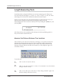
Area Measuring Tools . . . . . . . . . . . . . . . . . . . . . . . . . . . . . . . . . . . . . .7.38
Measure Area by Drawing a Closed Polyline .............................................7.38
Measure an Enclosed Area by Selecting the Boundary .................................7.39
Measure an Enclosed Area by Selecting an Interior Location .........................7.40
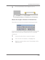
Length Measuring Tools . . . . . . . . . . . . . . . . . . . . . . . . . . . . . . . . . . . . .7.42
Measure the Distance Between Two Locations ..........................................7.42
TABLE
OF
CONTENTS
7
DynaSCAPE Design (Version 6.4)
Measure the Length or Perimeter of Selected Lines ................................... 7.43
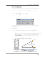
Measuring Angles . . . . . . . . . . . . . . . . . . . . . . . . . . . . . . . . . . . . . . . . . 7.45
Measure the Angle Between 2 Lines ...................................................... 7.45
Dimensioning Tools . . . . . . . . . . . . . . . . . . . . . . . . . . . . . . . . . . . . . . . 7.46
Insert a Linear Dimension .................................................................. 7.46
Insert a Horizontal Dimension ............................................................. 7.47
Insert a Vertical Dimension ................................................................ 7.48
Insert a Horizontal Baseline Dimension .................................................. 7.49
Insert a Vertical Baseline Dimension ..................................................... 7.50
Insert a Radius Dimension.................................................................. 7.51
Insert an Angle Dimension ................................................................. 7.53
Outline a Figure for Hatching. . . . . . . . . . . . . . . . . . . . . . . . . . . . . . . . . 7.54
Uncluster a Figure . . . . . . . . . . . . . . . . . . . . . . . . . . . . . . . . . . . . . . . . 7.55
8
Deleting and Revising Entities
8.1
Erasing Objects . . . . . . . . . . . . . . . . . . . . . . . . . . . . . . . . . . . . . . . . . . . 8.2
The Delete Entities Tool .....................................................................8.2
Object Grips . . . . . . . . . . . . . . . . . . . . . . . . . . . . . . . . . . . . . . . . . . . . . 8.3
Stretching Objects Using Grips ..............................................................8.3
Grip Tools: Move, Rotate, Resize and Mirror..............................................8.4
Revising Object Appearance and Settings . . . . . . . . . . . . . . . . . . . . . . . . . 8.7
Revising Objects Using the Settings Tables ...............................................8.7
Revising Objects Using the Edit Entity Attributes Panel ................................8.8
Revising Objects Using the Revise Entity Attributes Tool ...............................8.9
Revising Entities Within A Figure ......................................................... 8.10
TABLE OF CONTENTS
8
DynaSCAPE Software
Table of Contents
9
Inserting and Editing Text
9.1
Text Types in DynaSCAPE . . . . . . . . . . . . . . . . . . . . . . . . . . . . . . . . . . . 9.2
Inserting Text (no leader) . . . . . . . . . . . . . . . . . . . . . . . . . . . . . . . . . . . 9.3
Text Modifier Panel Options................................................................. 9.3
Insert Text Tool ............................................................................... 9.5
Insert Text Between Three Points Tool.................................................... 9.5
Insert Text Parallel to a Line................................................................ 9.6
Insert Text Above Existing Text ............................................................ 9.7
Insert Text Below Existing Text............................................................. 9.8
Insert Text Extracting the Attributes of Existing Text .................................. 9.9
Insert Text Attached to a Text Node .....................................................9.10
Insert Text Along a Flowing Line ..........................................................9.11
Inserting Text with a Leader . . . . . . . . . . . . . . . . . . . . . . . . . . . . . . . . .9.13
Revising Text (no leader) . . . . . . . . . . . . . . . . . . . . . . . . . . . . . . . . . . . .9.17
Revising Text Using the Edit Entity Attributes panel...................................9.17
Revising Text Using the Edit Entity Attributes panel...................................9.18
Revising Text Using the Font Settings Tables............................................9.19
Revising Text with a Leader . . . . . . . . . . . . . . . . . . . . . . . . . . . . . . . . . .9.21
Revising Text of a Single Label ............................................................9.21
Revising Text and Properties of a Multiple Labels ......................................9.22
Revising Text, Font Style, Font Size and Leader........................................9.22
Changing Global Text Settings . . . . . . . . . . . . . . . . . . . . . . . . . . . . . . . .9.24
Changing the Global Text Size or Font (no leader) .....................................9.24
Changing Label Text Settings (Dimension Text)........................................9.26
Changing Leader Settings ..................................................................9.28
Text Shortcuts . . . . . . . . . . . . . . . . . . . . . . . . . . . . . . . . . . . . . . . . . . .9.32
TABLE
OF
CONTENTS
9
DynaSCAPE Design (Version 6.4)
10
Selecting and Filtering Entities
10.1
Selecting Objects . . . . . . . . . . . . . . . . . . . . . . . . . . . . . . . . . . . . . . . . . 10.2
Selecting Objects by Clicking on Them .................................................. 10.2
Using a Left-to-Right Selection Window ................................................. 10.3
Using a Right-to-Left Selection Window ................................................. 10.4
Selecting All Objects in a Drawing........................................................ 10.4
Working with Layer Controls . . . . . . . . . . . . . . . . . . . . . . . . . . . . . . . . . 10.6
Locking a Layer .............................................................................. 10.6
Using an Entity Filter ....................................................................... 10.7
Isolating Layers Using Modes .............................................................. 10.9
11
Working with Library Figures
11.1
Selecting and Inserting a Library Figure . . . . . . . . . . . . . . . . . . . . . . . . . 11.2
Finding and Choosing a Library Figure ................................................... 11.2
Inserting a Library Figure .................................................................. 11.3
Clustering a Library Figure . . . . . . . . . . . . . . . . . . . . . . . . . . . . . . . . . . 11.8
How to Cluster a Library Figure ........................................................... 11.8
Why Do Figure Libraries Fail to Load or Seem to Disappear? ........................ 11.12
Creating a Custom Library Figure . . . . . . . . . . . . . . . . . . . . . . . . . . . . . 11.14
Adding a New Library ...................................................................... 11.14
Before Adding a New Figure .............................................................. 11.15
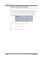
Adding A Figure to a Library .............................................................. 11.21
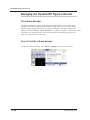
Managing the DynaSCAPE Figure Libraries . . . . . . . . . . . . . . . . . . . . . . . 11.26
How to Find the Library Manager ........................................................ 11.26
The Library Manager Panel ............................................................... 11.27
The Library Manager Controls ............................................................ 11.27
How to Activate a New Figure Library .................................................. 11.28
TABLE OF CONTENTS
10
DynaSCAPE Software
Table of Contents
Setting the Library Layer Override ...................................................... 11.29
Sort the Figure Libraries .................................................................. 11.31
Figure Ordering Controls.................................................................. 11.32
12
Labeling Plants & Design Elements
12.1
The Plant Labeling Panel . . . . . . . . . . . . . . . . . . . . . . . . . . . . . . . . . . . .12.2
1. What are My Plants? ......................................................................12.2
2. What is the Online Plant Database?....................................................12.3
3. What are My Favorites? ..................................................................12.3
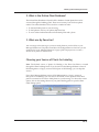
Choosing your Source of Plants for Labeling.............................................12.3
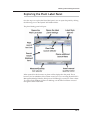
Exploring the Plant Label Panel . . . . . . . . . . . . . . . . . . . . . . . . . . . . . . .12.7
Creating a Local Database of Plants (My Plant List) . . . . . . . . . . . . . . . . . .12.8
The Plant List Editor.........................................................................12.8
Adding Plants to My Local Plant List ......................................................12.9
Matching Plants to the Online Plant Database . . . . . . . . . . . . . . . . . . . . . 12.22
Matching and Updating Plants Individually............................................. 12.22
Matching Plants Using the Batch Matching Wizard.................................... 12.24
Using Custom Images for My Plants (New!) ............................................ 12.28
Plant Sizes in the Plant List Editor ...................................................... 12.29
Creating and Managing Multiple Lists ................................................... 12.32
Creating a List of Favorites............................................................... 12.33
Finding Plants for Labeling ............................................................... 12.34
Placing a Softscape Label. . . . . . . . . . . . . . . . . . . . . . . . . . . . . . . . . . . 12.42
Auto-Minimize .............................................................................. 12.42
Auto-Rounding.............................................................................. 12.42
Layer Override ............................................................................. 12.43
Determining the Quantity ................................................................ 12.43
Inserting a Plant Label Using AutoCount ............................................... 12.44
TABLE
OF
CONTENTS
11
DynaSCAPE Design (Version 6.4)
Inserting a Plant Label Using a Measuring Tool ........................................ 12.45
Inserting a Plant Label by Entering Quantity Manually ............................... 12.46
Available Labeling Styles .................................................................. 12.49
Using Keyed Labels (with leaders) ....................................................... 12.50
Inserting Plant Schedules ................................................................. 12.54
Setting up your Design Labels (for Materials) . . . . . . . . . . . . . . . . . . . . . 12.60
Exploring the Design Label Panel ........................................................ 12.60
Creating a List of Design Labels.......................................................... 12.61
Finding and Inserting Design Labels ..................................................... 12.63
Linking a Design Label to a Material or Kit ............................................. 12.67
Using Estimating Labels. . . . . . . . . . . . . . . . . . . . . . . . . . . . . . . . . . . . 12.71
Finding and Inserting Estimating Labels using Manage Website..................... 12.72
Finding and Inserting Estimating Labels using Legacy Q/M .......................... 12.73
Creating a Material List from a Drawing. . . . . . . . . . . . . . . . . . . . . . . . . 12.74
Exporting a Material List from a Drawing to Word/Excel ............................ 12.74
Creating a Quote from a DynaSCAPE Drawing . . . . . . . . . . . . . . . . . . . . . 12.77
Grouping Labels into Work Areas for Manage360 (Manage Website) and Legacy Q/M..
12.77
Exporting to DS|Manage360 (Manage Website) ........................................ 12.80
Exporting to Legacy Q/M (DS|Quote or DS|Manage).................................. 12.80
Creating a Plant Picture Catalogue (PDF). . . . . . . . . . . . . . . . . . . . . . . . 12.84
13
Working With Raster Images
13.1
About Raster Images in DS|Design . . . . . . . . . . . . . . . . . . . . . . . . . . . . . 13.2
Best Practices for Raster Images.......................................................... 13.2
Unique Tools for Raster Images ........................................................... 13.2
Raster Image Names ........................................................................ 13.3
Inserting Raster Images..................................................................... 13.3
TABLE OF CONTENTS
12
DynaSCAPE Software
Table of Contents
Raster Image Files and DS|Design Drawings .............................................13.3
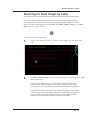
Finding and Inserting Plant Images . . . . . . . . . . . . . . . . . . . . . . . . . . . . .13.4
Searching for Plant Images at dynascape.com ..........................................13.4
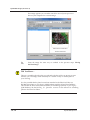
Searching for Plant Images in My Plants..................................................13.7
Searching for Custom Images ..............................................................13.9
Searching for Plant Images by Label . . . . . . . . . . . . . . . . . . . . . . . . . . . 13.11
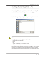
Inserting a Raster Image from a File . . . . . . . . . . . . . . . . . . . . . . . . . . . 13.13
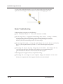
Raster Troubleshooting ................................................................... 13.14
Moving and Resizing a Raster Image. . . . . . . . . . . . . . . . . . . . . . . . . . . . 13.15
Moving a Raster Image (no border)...................................................... 13.15
Moving a Raster Image With a Border................................................... 13.15
Resizing an Image to the Drawing Scale . . . . . . . . . . . . . . . . . . . . . . . . . 13.17
Editing or Removing a Raster . . . . . . . . . . . . . . . . . . . . . . . . . . . . . . . . 13.19
Changing the Raster Name ............................................................... 13.19
Adjusting the Raster Location ........................................................... 13.20
Turning Raster Visibility On and Off .................................................... 13.20
Permanently Removing a Raster Image................................................. 13.21
Tips for Scanning Lot Plans ............................................................... 13.21
How to Resize a Picture using Paint . . . . . . . . . . . . . . . . . . . . . . . . . . . 13.22
14
Printing and Saving as an Image File 14.1
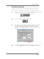
Printing DynaSCAPE Drawings (no images) . . . . . . . . . . . . . . . . . . . . . . . .14.2
Printing Drawings Without Images (black output) ......................................14.2
Printing Drawings with Raster Images . . . . . . . . . . . . . . . . . . . . . . . . . . .14.6
Missing Figures When Printing .............................................................14.9
Saving a Drawing as a JPEG or Adobe PDF . . . . . . . . . . . . . . . . . . . . . . . 14.10
Choosing an Image File Type to Save to................................................ 14.10
TABLE
OF
CONTENTS
13
DynaSCAPE Design (Version 6.4)
Saving a Drawing as a JPEG Image....................................................... 14.10
Changing Output Colors to Black......................................................... 14.12
Saving a Drawing as an Adobe PDF ...................................................... 14.13
Resetting the PDF Writer.................................................................. 14.15
Sending a Drawing Out to a Print Shop . . . . . . . . . . . . . . . . . . . . . . . . . 14.16
Print Shop Prints Are Too Light .......................................................... 14.16
Print Shops vs. Your Own Printer? ....................................................... 14.16
15
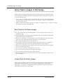
Design Tutorial: Part I
15.1
The DynaSCAPE Design Tutorial ........................................................... 15.2
Drafting the Base Plan . . . . . . . . . . . . . . . . . . . . . . . . . . . . . . . . . . . . . 15.3
Selecting a New Drawing Sheet (Prototype) ............................................ 15.3
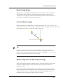
Drawing the House Outline ................................................................ 15.3
Drawing the Other Base Plan Elements .................................................. 15.8
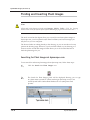
Drawing the Hardscape Elements . . . . . . . . . . . . . . . . . . . . . . . . . . . . . 15.20
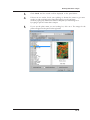
Drawing the Walkway and Step .......................................................... 15.20
Inserting the Walkway Border and Patterns ........................................... 15.27
Drawing the Plant Bed Line ............................................................... 15.34
Adding Library Figures to the Design . . . . . . . . . . . . . . . . . . . . . . . . . . 15.39
Inserting the Rocks ......................................................................... 15.39
Inserting the Shrub Symbols .............................................................. 15.40
Inserting The Boxwood Hedge ............................................................ 15.42
Inserting the Tree Symbols ............................................................... 15.46
Making a Backup File for a Drawing ..................................................... 15.51
Clustering the Plant Symbols ............................................................. 15.52
Adding the Titleblock . . . . . . . . . . . . . . . . . . . . . . . . . . . . . . . . . . . . . 15.54
Placing the North Arrow................................................................... 15.57
TABLE OF CONTENTS
14
DynaSCAPE Software
Table of Contents
16
Design Tutorial: Part II
16.1
Labeling the Plants . . . . . . . . . . . . . . . . . . . . . . . . . . . . . . . . . . . . . . . .16.2
Labeling Design Elements (Hardscapes) . . . . . . . . . . . . . . . . . . . . . . . . . .16.7
Setting up the Design Labeling List .......................................................16.7
Labeling the Design Elements..............................................................16.9
Adding the Text and Labels . . . . . . . . . . . . . . . . . . . . . . . . . . . . . . . . . 16.12
Simple Text Labels......................................................................... 16.12
Inserting Text With a Leader............................................................. 16.15
Inserting Plant Images . . . . . . . . . . . . . . . . . . . . . . . . . . . . . . . . . . . . . 16.17
Searching for Plant Images by Label .................................................... 16.17
Creating a Material List . . . . . . . . . . . . . . . . . . . . . . . . . . . . . . . . . . . . 16.20
Creating a Plant Picture Catalogue (PDF) . . . . . . . . . . . . . . . . . . . . . . . . 16.22
Printing the Drawing . . . . . . . . . . . . . . . . . . . . . . . . . . . . . . . . . . . . . . 16.25
17
Drawings
Importing & Exporting AutoCAD®
17.1
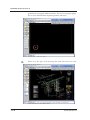
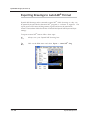
Importing an AutoCAD® Drawing into DynaSCAPE . . . . . . . . . . . . . . . . . . .17.2
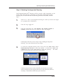
Step 1: Importing an AutoCAD® Drawing.................................................17.2
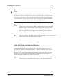
Step 2: Resizing the Imported Drawing...................................................17.5
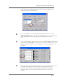
Step 3: Editing the Imported Drawing ....................................................17.6
Troubleshooting AutoCAD® Importing ....................................................17.8
Exporting Drawings to AutoCAD® Format . . . . . . . . . . . . . . . . . . . . . . . . 17.10
Importing NuPoints® Site Capture Pro data . . . . . . . . . . . . . . . . . . . . . . 17.13
Redrawing the Building Outline.......................................................... 17.15
TABLE
OF
CONTENTS
15
DynaSCAPE Design (Version 6.4)
18
Customizing and Other Advanced Topics
18.1
Creating Custom Prototypes (templates) . . . . . . . . . . . . . . . . . . . . . . . . . 18.2
Creating Custom Titleblocks . . . . . . . . . . . . . . . . . . . . . . . . . . . . . . . . . 18.5
Setting Up a Custom Titleblock ........................................................... 18.5
Saving a Custom Titleblock ................................................................ 18.7
Customizing Toolboxes . . . . . . . . . . . . . . . . . . . . . . . . . . . . . . . . . . . . . 18.9
Editing Existing Toolboxes ................................................................. 18.9
Creating a New Toolbox ................................................................... 18.12
Copying into a New DynaSCAPE Prototype . . . . . . . . . . . . . . . . . . . . . . . 18.14
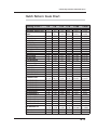
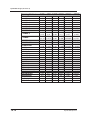
Hatch Pattern Scale Chart . . . . . . . . . . . . . . . . . . . . . . . . . . . . . . . . . . 18.15
TABLE OF CONTENTS
16
DynaSCAPE Software
1
Installing DynaSCAPE
Design
Topics covered in the Preface:
Disclaimer
Installation of DynaSCAPE Design
Checking for Internet Updates
Uninstalling DynaSCAPE Design
1.1
DynaSCAPE Design (version 6.4)
Introduction to this Guide
How to Use This Manual
This manual is meant to be read from start to finish and contains information
necessary to familiarize you with the basic features found in DynaSCAPE, to give you
a high level of proficiency with the program.
Typographical Conventions
• Italics are used for new terms whose definition will follow the introduction of the
term.
• Boldface is used for emphasis.
• Terms in square brackets, such as [Ctrl], [Esc], [Shift], [F1], refer to keys on the keyboard. Keyboard sequences are described in the following manner: “Use the shortcut [Ctrl + A]. (Hold [Ctrl] and press [A].)” Or, “Hold the [Ctrl] key and press [H].”
• Command paths are described as follows: Environment | Drawing Page means
click the Environment button from the menu and the Drawing Page from the pulldown menu displayed.
• Notes: Notes call your attention to important points, and are formatted in italics.
• Instructions or other information displayed in DynaSCAPE’s Prompt Line or Command Line Interpreter (CLI) are given in Arial font, for example, “Select ‘from’
translate location”.
Mouse and Keyboard Conventions
In DynaSCAPE (as in all Windows programs) there is a shared convention about twobutton mouse commands. The following list defines some common terminology:
• Choose is equivalent to the terms click, select, and Click.
• Click means to click and release the left mouse button once and is equivalent to the
terms Click and select.
• Right-click means to click and release the right mouse button. Clicking the right
mouse button is often equivalent to pressing the [Spacebar], which is used primarily to indicate that a selection process is complete.
• Click and drag means to click and hold the left mouse button down while you
move the mouse and drag an object to a new location with it.
• Double-click means to click the left mouse button rapidly two times.
Click means to click and release the left mouse button once and is equivalent to the
terms click, choose and select.
1.2
DynaSCAPE Software
Installing DynaSCAPE Design
Other Terminology
• Pictorial buttons on the screen are often referred to as icons in the manual; buttons
with text names are referred to simply as buttons.
• Pressing the pull-down menu Help >> Contents >> Index will allow you to search
DynaSCAPE’s Help topics for any term.
1.3
DynaSCAPE Design (version 6.4)
Installation of DynaSCAPE Design
Installation Overview
Before installing DynaSCAPE Design, read and understand this section to ensure
your installation proceeds smoothly. Make sure your workstation(s) are properly
prepared for installation to save time and effort. Attempting to install on a
workstation that does not meet basic system requirements creates performance
problems, software failure, or even system problems. Consult the System
Requirements section within this chapter to ensure your workstation meets the basic
requirements.
Note: — Software problems can stem from a variety of sources, but the source of most
installation problems stem from an improperly configured workstation.
Important
Please take a few minutes to review the pre-installation checklist to ensure that the target
computer meets/exceeds the minimum system requirements.
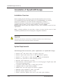
System Requirements
The following are the recommended system requirements for DynaSCAPE Design:
• Windows XP® with Service Pack 3 or higher, 32-bit only
• Windows Vista® with Service Pack 2 (with all Windows updates)
•
•
•
•
•
•
•
•
•
•
1.4
Windows 7® with 32-bit or 64-bit operating systems (recommended)
Windows 8.1 with 32-bit or 64-bit operating systems
Microsoft .NET Framework 3.5 or later
Install Windows with the English version or set the language to English (may need
to download a language pack)
1 gigahertz (GHz) 32-bit (x86) or 64-bit (x64) processor
1 gigabyte (GB) of system memory (RAM)
512MB video card with support for DirectX 9 graphics
Minimum screen resolution of 1024 x 768 pixels
Microsoft Internet Explorer TM 8 or later
Internet connection (updates and access to the online plant database)
DynaSCAPE Software
Installing DynaSCAPE Design
Note: Office Suite 2003TM (or later) software is required for exporting materials to
ExcelTM and WordTM. Adobe Reader TM software is required for exporting plant picture
catalogues.
Required Skills
• Basic Windows Proficiency including file creation, deletion, moving, and attaching files to e-mail messages.
Note: DynaSCAPE Software’s Technical Support cannot help users whose
workstations do not meet the basic requirements described above. Technical Support
cannot walk users through the operation of Third Party applications (programs other
than DynaSCAPE Design and the DynaSCAPE Online Plant Database).
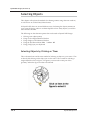
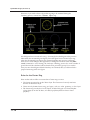
Did You Know...
To get information about your operating system, processor speed, and RAM, simply
right-click your My Computer icon and select Properties. The General tab displays
your system information.
To display/set your monitor’s resolution, right-click anywhere on your desktop (i.e.
make sure you are not right-clicking an existing icon or shortcut), then select Display
(or click on Personalize and then Display and then Adjust Resolution).
Your Screen resolution must be set at a minimum of 1024 x 768. DynaSCAPE Design
supports screen resolutions greater than 1024 x 768, but nothing less.
1.5
DynaSCAPE Design (version 6.4)
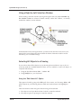
To find out how much free space is on your hard disk, open a My Computer window.
Right-click the drive on which you wish to install DynaSCAPE Design, (typically your
C: drive) and make sure the drive’s Free Space reads at least 800MB. Note: 1GB =
1000MB. If it’s less than 1GB then free up some space before installing.
Pre-Installation Checklist
If your system requirements are sufficient for DynaSCAPE Design installation, run
through the following pre-installation checklist. The pre-installation checklist is
particularly important for workstations that have access to the Internet. Spyware,
adware, trojans and other viruses are often the causes for installation difficulties.
Uninstall
any older versions of DynaSCAPE software (Garden Graphics
Software) that may have been installed on this workstation. Remember: for
maximum protection, back-up and copy any existing Legacy DS|Quote/
Manage (or IRIS) databases to another location, either a different directory on
your hard drive or to a removable media device such CD, DVD or USB drive,
before uninstalling. (Legacy Quote or Manage do not need to be uninstalled for
DynaSCAPE Design Version 6.)
Scan
for and remove any viruses from the workstation. If no anti-virus software
is installed on the workstation, it is highly recommended that some be installed.
Viruses can affect the proper installation of any software. If the workstation
does have anti-virus software installed, ensure that the virus definitions are upto-date.
Scan
for and remove any spyware or adware from the workstation. If the
workstation is or has ever been connected to the Internet, it is highly
recommended that all spyware or adware be removed from the workstation
using anti-spyware software. If you don’t have anti-spyware software installed,
download an appropriate spyware removal software package and clean the
workstation.
Reboot
the workstation. Rebooting the workstation clears any applications that
may be lingering in memory and restarts all the necessary system services.
Did You Know...
There are several, excellent free versions of both anti-virus and anti-spyware
applications available on the Internet. The software can be downloaded, installed and
updated at no cost to you.
1.6
DynaSCAPE Software
Installing DynaSCAPE Design
Before selecting any “free” software however, get some recommendations from
someone knowledgeable in the field. Some free anti-spyware applications are actually
spyware in disguise and must be avoided.
Note: These free products are intended for non-commercial use. Please make sure you
meet the licensing requirements before installing and using their software, and note
that DynaSCAPE Software will not provide support with regards to these programs.
Important:
1. Prior to starting the installation, turn off (or disable) all firewalls and virus
scanning software.
2. After installation is complete, please check for updates.
3. Once the update process is complete, the firewall and virus scanning can be reenabled.
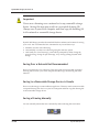
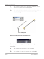
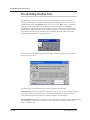
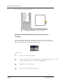
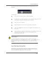
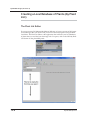
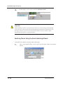
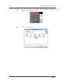
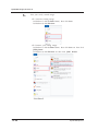
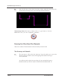
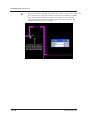
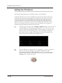
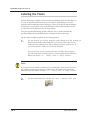
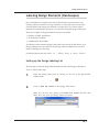
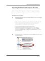
1.
Install DynaSCAPE Design. Insert the USB into your computer. and the
USB content should automatically appear. If it fails to appear, press the
Windows Start button then type “D:\DynaSCAPEInstall.exe”, where D: is the
letter associated with your USB drive. If your USB drive is associated with
another letter, type that letter instead.
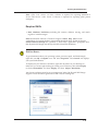
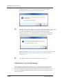
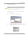
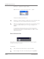
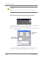
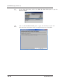
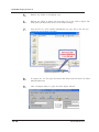
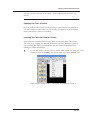
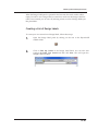
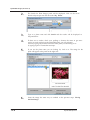
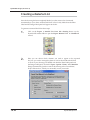
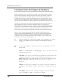
2.
When you see the User Account Control , click Yes to continue with the
installation. The Install Shield Wizard appears on the screen, which will
guide you through the installation process.
1.7
DynaSCAPE Design (version 6.4)
1.8
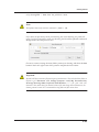
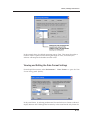
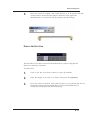
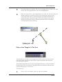
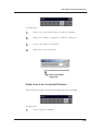
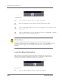
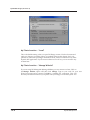
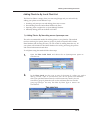
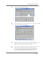
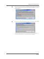
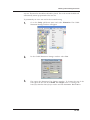
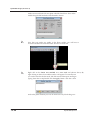
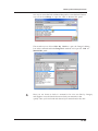
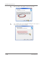
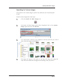
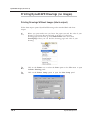
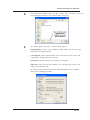
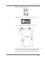
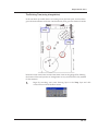
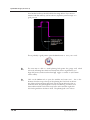
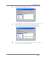
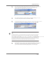
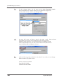
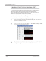
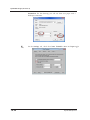
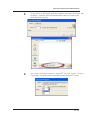
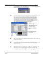
3.
The first panel is the Welcome Screen. Click Next.
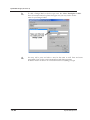
4.
The second panel is the License Agreement. Read the agreement carefully
and if you agree, click Next.
DynaSCAPE Software
Installing DynaSCAPE Design
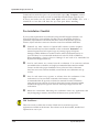
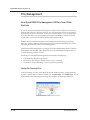
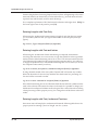
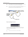
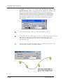
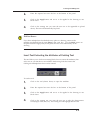
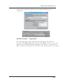
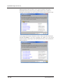
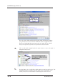
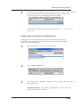
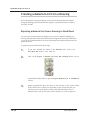
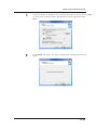
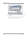
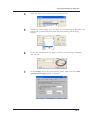
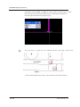
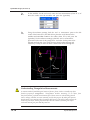
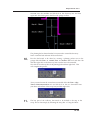
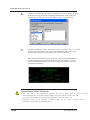
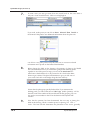
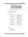
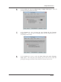
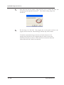
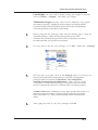
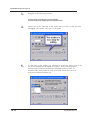
5.
The third panel called the Customer Information will prompt you to type
your name and the name of your company (insert if applicable).
6.
Type in the valid serial numbers you have been given.
Note: Serial numbers are case sensitive.
Important
Attach your serial numbers to the back of your DynaSCAPE Design CD case and store your
case somewhere safe and accessible. You will need your serial numbers should you ever be
required to reinstall DynaSCAPE Design.
Select the Next button when you are ready to proceed.
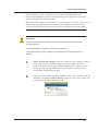
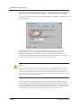
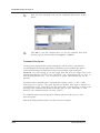
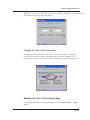
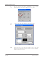
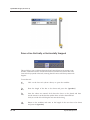
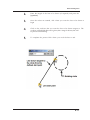
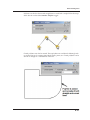
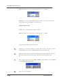
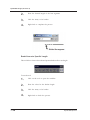
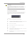
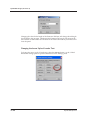
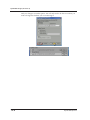
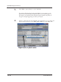
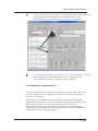
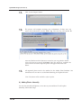
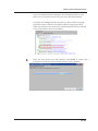
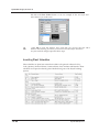
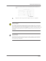
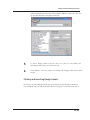
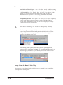
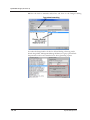
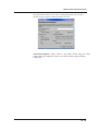
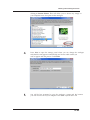
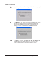
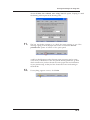
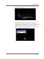
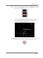
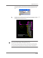
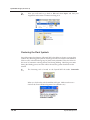
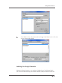
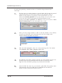
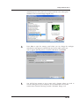
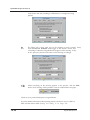
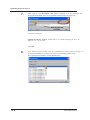
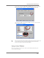
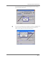
7.
The fourth panel called Choose Destination Location allows you to either
proceed with the default installation of the program to the C: drive in your
computer, or to use the Browse button to choose an alternative location for
1.9
DynaSCAPE Design (version 6.4)
the installation of the program. It is recommended it use the default drive
C. Click Next.
1.10
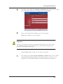
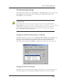
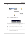
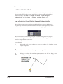
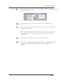
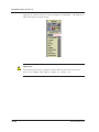
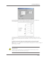
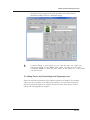
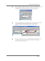
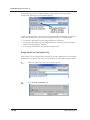
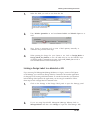
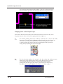
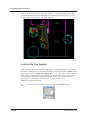
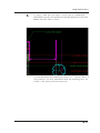
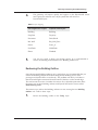
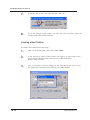
8.
The installation will begin. It may take a few minutes to install.
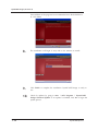
9.
Click Finish to complete the installation. DynaSCAPE Design is ready to
use.
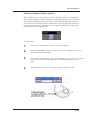
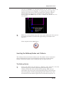
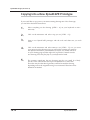
10.
Check for updates by going to Start | (All) Programs | DynaSCAPE
Design| Check for Updates. If an update is available, click Yes to begin the
update process.
DynaSCAPE Software
Installing DynaSCAPE Design
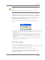
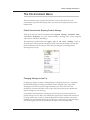
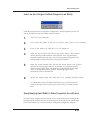
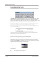
Checking for Internet Updates
Periodically, DynaSCAPE Software will release updates to the DynaSCAPE Design.
These updates are free for all users with an active subscription. Typically, updates will
provide bug fixes, product enhancements, or increased usability. Besides updating
after the initial installation, we recommend that you check for updates on at least a
monthly basis, or whenever the software is re-installed.
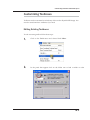
Updating DynaSCAPE
To check for updates select Start | (All) Programs | DynaSCAPE | Design| Check
for Updates. If an update is available, click Yes to begin the update process.
Important:
If you are running a version that is more than one year old you may need to check for updates
several times to download all the available updates. DynaSCAPE will usually releases two or
more updates each year.
Updating to DynaSCAPE Version 6 from an Older Version
If you are running a version older than 5 you cannot update to version 6 via an
internet update. Version 6 can only be obtained by a fresh install with a DynaSCAPE
Version 6 install CD. You must uninstall any older versions of DynaSCAPE before
installing Version 6. Make sure you back up any customizations first.
If you are running version 6 you can check for and run updates from your Start
button.
1.11
DynaSCAPE Design (version 6.4)
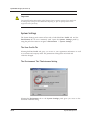
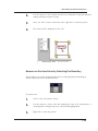
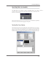
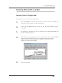
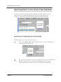
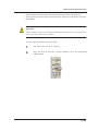
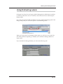
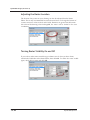
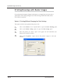
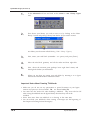
Uninstalling DynaSCAPE Design
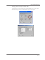
To remove DynaSCAPE Design from your computer, follow these steps:
1.12
1.
2.
Back up any customizations i.e. library figures, prototypes, hatch patterns
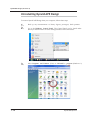
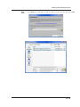
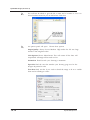
3.
Select Programs and Features (Vista) or Uninstall a program (Windows 7).
Go to the Windows Control Panel. The Control Panel can be found either
directly in the Start menu or in the Settings submenu of the Start menu.
DynaSCAPE Software
Installing DynaSCAPE Design
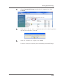
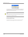
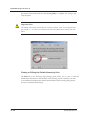
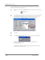
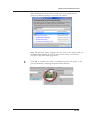
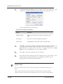
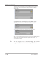
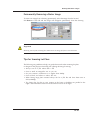
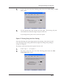
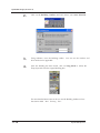
4.
Choose DynaSCAPE Design from the list of programs, then click
Uninstall.
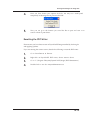
5.
When asked, “Do you want to completely remove the selected application
and all of its components?”, click Yes.
6.
When the installation is complete, click Finish.
It is best to restart your computer prior to reinstalling DynaSCAPE Design.
1.13
DynaSCAPE Design (version 6.4)
1.14
DynaSCAPE Software
2
Getting Started
Topics covered in this chapter:
Starting the DynaSCAPE Design program for the first time
Opening a new drawing using prototypes
Touring the screen: toolboxes, toggles and tools
Creating and saving DynaSCAPE Design drawings.
Drawing Navigation
2.1
DynaSCAPE Design (version 6.4)
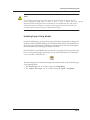
Starting DynaSCAPE Design
Starting the DynaSCAPE Design Program
The Windows Setup (installation) program creates a program group and appropriate
program icons for the application.
To run DynaSCAPE Design in Windows XP, Vista, 7 or 8.1:
1.
Select the DynaSCAPE Design icon on your desktop. The installation
routine will create a shortcut icon for DynaSCAPE Design on your
Desktop.
2.
Select the Windows Start button at the bottom-left of your screen. Choose
All Programs > DynaSCAPE > Design > DynaSCAPE Design.
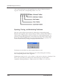
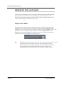
Software Activation
The first time you run DS|Design, DynaSCAPE will attempt to activate your software
license. Activation protects you by ensuring that you have licensed a genuine
DynaSCAPE product rather than a counterfeit. Activation protects DynaSCAPE by
ensuring that our software is used in accordance with a purchased license. You will
not be able to use your DynaSCAPE software if it is not activated.
Important Note about Activation
You need an internet connection for activation, so it is important that your computer is
connected to the internet when you start DS|Design for the first time.
Activation will begin automatically when start DS|Design the first time and will only
take a few seconds to complete. If your software fails to activate, either because it
cannot connect to DynaSCAPE over the Internet or because its use is found not to be
permitted, DS|Design will not operate until activation has been successfully
completed. The activation process will only run the first time you open DS|Design
after installation.
2.2
DynaSCAPE Software
Getting Started
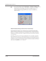
What to do if your Activation is Declined
If your software could not be activated, it could be for the following reasons:
1. You have installed the software on more computers than is allowed under the software license agreement
2. Someone else is using your serial number and has already installed the software
3. You do not have an internet connection or your firewall is blocking the connection
4. Your date, time or timezone is incorrect.
5. The problem is on DynaSCAPE Software’s end and needs to be rectified.
If you have installed the software on one or more other computers, you can deactivate
those installations to free up one of your activations and try again. You can
‘deactivate’ the license by going to Help > Deactivate DynaSCAPE Design...
If you have problems connecting to the internet or you cannot deactivate the software
on another computer or do not have a connection or if you believe you should be able
to activate, you can call DynaSCAPE Support at 1.800.710.1900 Ext 1
Click Cancel to exit activation, click Retry to retry activation or Manual Activation to
enter an activation code from DynaSCAPE.”
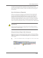
Manual Activation
To acquire an activation code should you need one, please call DynaSCAPE at
1.800.710.1900. Enter the code in the field provided in the Manual Activation message
box and click Activate.
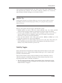
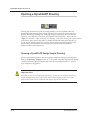
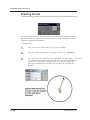
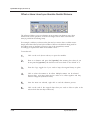
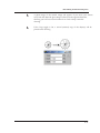
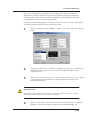
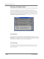
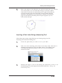
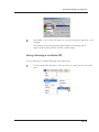
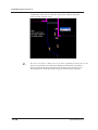
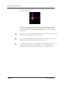
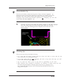
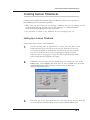
When DynaSCAPE Design Opens for the First Time
When DynaSCAPE Design opens for the first time, the Drawing Window opens to a
DynaSCAPE Design prototype with a white background and instructions explaining
how to open a new drawing. Close this drawing by selecting the pull-down menu File
| Close All. You do not need to save this drawing. In the future when you open
DynaSCAPE Design, the last drawing(s) that you were working on will be displayed
to you. Many menus and features of the program are not accessible (and will look dim
or gray) when there are no drawings open in the Drawing Window. In order to access
all of the features examined in the pages that follow, we need to open a prototype
drawing.
2.3
DynaSCAPE Design (version 6.4)
What is a Prototype Drawing?
Prototype drawings (also called Templates) are designed to make the start-up phase of
creating a new drawing quick and easy. They are drawings that have many preloaded settings that other programs would require you to set up. These settings
include, but are not limited to, line weights, layers and dimension styles for many
scales and paper sizes. Choosing one of DynaSCAPE Design’s many prototypes will
allow you to begin work on drafting your plan immediately.
As you evolve as a DynaSCAPE Design user you may wish to alter the existing
prototypes or add new prototypes to the program, which DynaSCAPE Design will
allow you to do. However, we strongly recommend that you leave such advanced
modifications for later, and start your first projects using the default prototypes that
shipped with the software.
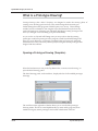
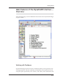
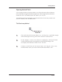
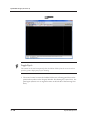
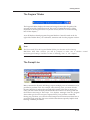
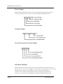
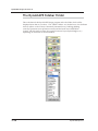
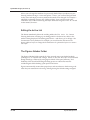
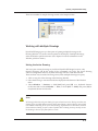
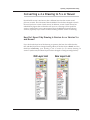
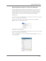
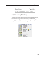
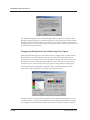
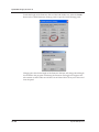
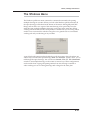
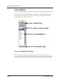
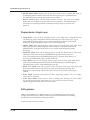
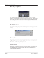
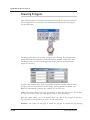
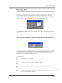
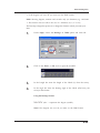
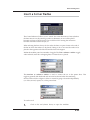
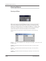
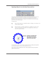
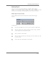
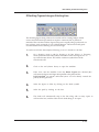
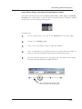
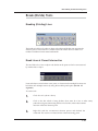
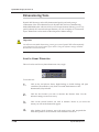
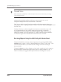
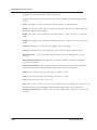
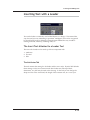
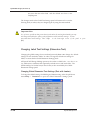
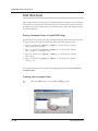
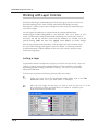
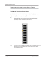
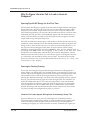
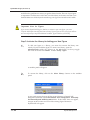
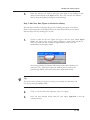
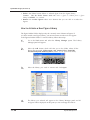
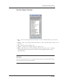
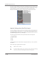
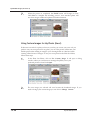
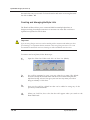
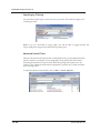
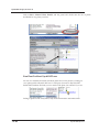
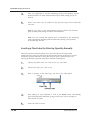
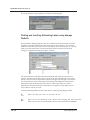
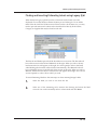
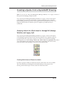
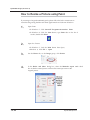
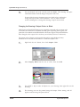
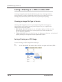
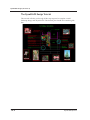
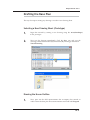
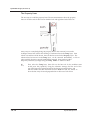
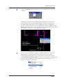
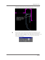
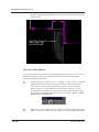
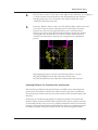
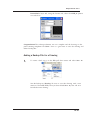
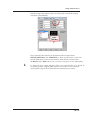
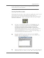
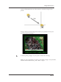
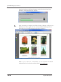
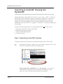
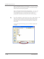
Opening a Prototype Drawing (Template)
Select the first button (or icon) in the Top Button Bar, “Activate a new drawing”, to
open the New Drawing panel.
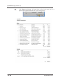
The New Drawing panel, as shown below, displays the list of all available prototype
drawings.
The scroll bar on the right side of the list allows you to see all of the prototype
drawing names. The list is sorted alphabetically by name and by page size (from
smallest to largest); metric prototypes are located at the bottom of the list.
2.4
DynaSCAPE Software
Getting Started
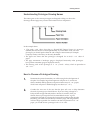
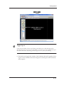
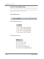
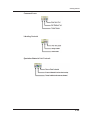
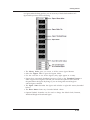
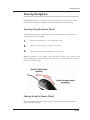
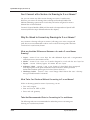
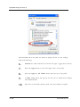
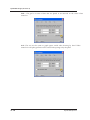
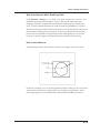
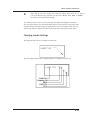
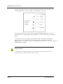
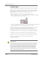
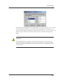
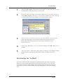
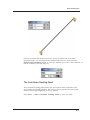
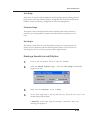
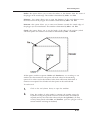
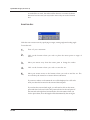
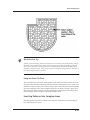
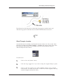
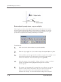
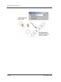
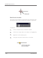
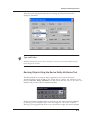
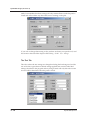
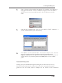
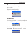
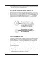
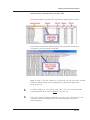
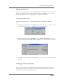
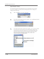
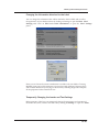
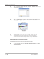
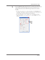
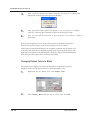
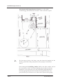
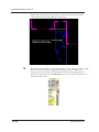
Understanding Prototype Drawing Names
The names given to the various prototypes are designed to help you choose the
drawing scale and page size you need. Each name has four components:
In the example above:
The prefix “v6.0” shows that this is a DynaSCAPE Design Version 6.0 prototype
(Default). Because the list is sorted alphabetically, if you decide to create your own
prototypes you should preface them all with a unique version name (for example:
Company Name) so that they can be easily identified.
• The paper size shows that this prototype is designed for an 8-1/2” x 11” sheet of
paper.
• The page orientation is landscape (page is displayed horizontal); other prototypes
have portrait orientation (page is displayed vertical).
• The drawing scale of this prototype is 1” = 4’ (1 inch = 4 feet), which is equivalent to
1/4” = 1’-0”.
•
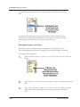
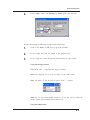
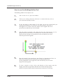
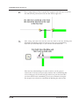
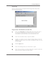
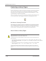
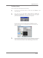
How to Choose a Prototype Drawing
1.
Determine the printer format that you will be using for the final printout of
the plan. For example, large-format printers will print on C- and D-size
sheets; standard desktop printers will print on letter-size (8.5” x 11”) paper,
while some will print on tabloid (ledger) size sheets (11” x 17”).
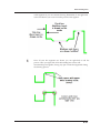
2.
Consider the true size of the area that the plan will cover to help determine
the scale of prototype you should choose. If you are doing a design for a
backyard that is approximately 80 feet x 60 feet, for instance, then you
should choose a prototype that will accommodate that area. A good
general rule of thumb is to choose the lowest scale possible so that the plan
(including your labels and title block) will fill the page, and design details
will be as large as possible. For an 80 feet x 60 feet area printed on 8.5” x 11”
paper, you would choose a prototype with a 1”= 8’ scale.
2.5
DynaSCAPE Design (version 6.4)
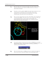
3.
Choose between landscape or portrait orientation. Again, this will be
determined by the size and shape of the project you are designing.
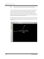
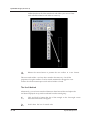
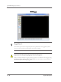
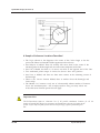
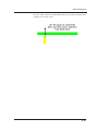
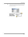
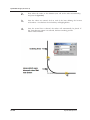
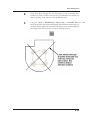
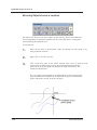
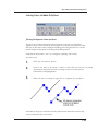
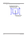
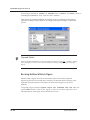
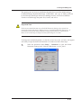
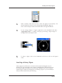
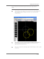
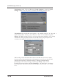
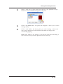
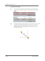
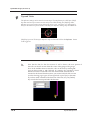
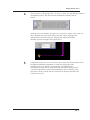
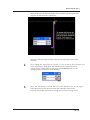
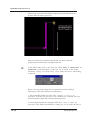
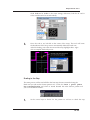
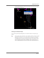
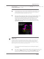
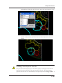
To choose a Prototype to work with, select the prototype name and then click [OK].
The New Drawing window with the Prototype list will close and a new (blank)
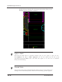
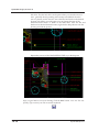
drawing will open in the Drawing Window. The blue dashed rectangle that is
displayed in the Drawing Window shows the limits (physical edge) of the drawing
page. You should draft your plan within these limits so that when you print your
drawing on the same size of sheet you chose as your prototype, your drawing will be
at the correct scale you chose with your prototype.
In DynaSCAPE Design, scale is relative to sheet size. When you change your drawing
scale, DynaSCAPE will adjust your drawing so that when you print to the same size
of paper as your drawing page setting, the printed drawing will be at the correct scale
for measuring.
2.6
DynaSCAPE Software
Getting Started
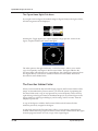
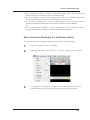
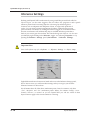
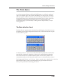
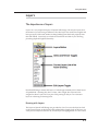
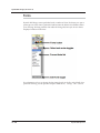
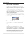
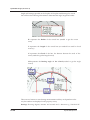
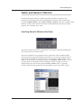
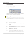
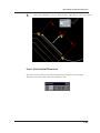
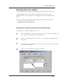
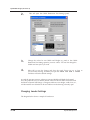
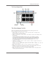
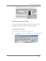
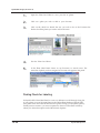
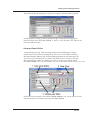
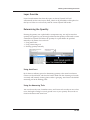
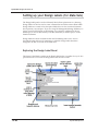
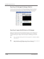
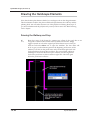
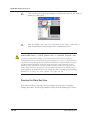
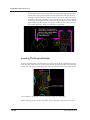
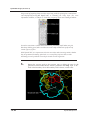
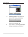
Main Features of the DynaSCAPE Interface —
Overview
In the following image, we have labelled the main features of the DynaSCAPE Design
program window.
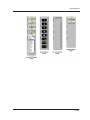
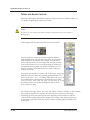
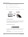
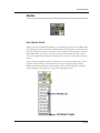
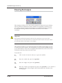
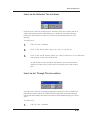
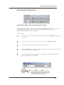
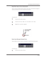
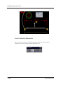
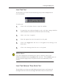
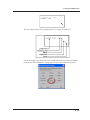
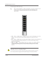
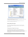
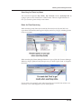
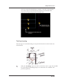
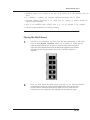
Working with Toolboxes
DynaSCAPE Design includes four main command toolboxes used to perform a host
of design operations. The most commonly used toolboxes are be opened (or closed)
using the “Qk St” (Quick Start), “Drw” (Draw), “Edit” (Edit), “Dim” (Dimension) and
2.7
DynaSCAPE Design (version 6.4)
“Adv” (Advanced) buttons on the Toggle Bar (shown below). These four buttons
toggle (or switch) each corresponding toolbox on or off.
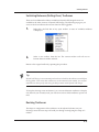
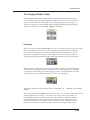
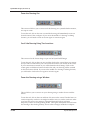
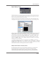
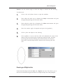
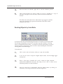
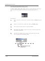
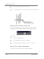
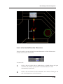
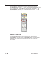
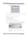
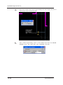
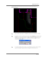
Opening, Closing, and Minimizing Toolboxes
Open any of the toolboxes shown above by clicking their corresponding toggle
buttons in the Toggle Bar. (The “Draw [Creation]” toolbox is shown below.) When a
toolbox opens, its toggle button will have red letters on a white background (the “on”
position). Clicking the toggle button a second time closes the toolbox, and the toggle
button will appear with black letters on a gray background (the “off” position). You
can also close a toolbox by clicking on the [X] on the toolbox itself.
The buttons in each toolbox are called command buttons or tools.
You can open and close as many toolboxes as you wish by clicking and re-clicking
their corresponding buttons in the Toggle Bar.
The Minimize control [-] rolls up the toolbox so that only its title bar is displayed. This
allows you to maximize your drawing area without having to close the toolbox
completely. Selecting Minimize [-] again restores the toolbox to its full size.
2.8
DynaSCAPE Software
Getting Started
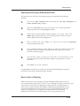
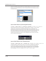
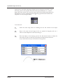
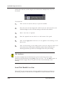
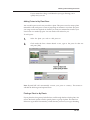
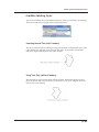
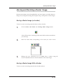
Switching Between (Rolling-Over) Toolboxes
There are four additional toolboxes available in DynaSCAPE Design that are not
available in the other versions of DynaSCAPE Design. The following steps give you
access to the four toolboxes that are not found on the Toggle Bar:
1.
Right-click the Title Bar of any open toolbox. A menu of available toolboxes
is displayed.
2.
Select a new toolbox from the list. The current toolbox will roll over to
become the new toolbox selected.
Return to the original toolbox by repeating the procedure.
Tip
DynaSCAPE Design’s most commonly used tools are included in the toolboxes accessible from
the Toggle Bar. Tools in the other toolboxes are not documented in this manual. You can find
information on these specific tools using the Help contents inside DynaSCAPE Design.
To keep the drawing screen uncluttered, you can switch between toolboxes to display
only the tools you currently need; you don’t have to have all the toolboxes open at one
time.
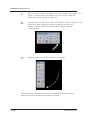
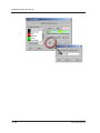
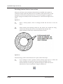
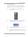
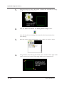
Resizing Toolboxes
The shape or configuration of the toolboxes can be adjusted to better suit your
drawing screen. The next steps will walk you through reconfiguring the shape of a
toolbox.
2.9
DynaSCAPE Design (version 6.4)
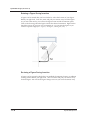
1.
Move the cursor to the bottom-right corner of a toolbox and position it so
that the cursor becomes a two-headed arrow. (The Tool Tip, “Click and
hold to resize panel”, will also be displayed.)
2.
Click and hold the left mouse button, then drag the mouse to the left (or the
right). The toolbox changes size and shape as you drag its corner: The
number of tool icons remains the same, but the number of rows and
columns changes.
3.
Release the mouse when the desired size is reached.
DynaSCAPE Design remembers how you have configured the toolboxes and will
retain this configuration even after the toolboxes are closed.
2.10
DynaSCAPE Software
Getting Started
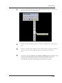
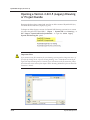
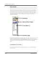
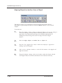
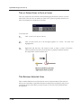
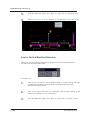
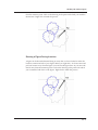
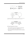
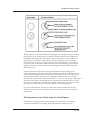
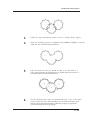
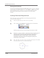
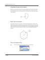
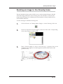
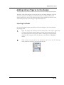
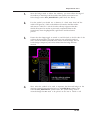
Opening Nested Tools
If you examine the Draw [Creation] toolbox, you will see that some of the tool buttons
have a small blue triangle in the bottom-right corner. This triangle indicates that other
buttons are nested (or hidden) below the button you can see.
Two methods can be used to display or use the nested tools: the tear-away method and
the scroll method, each described below.
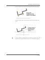
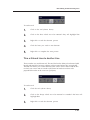
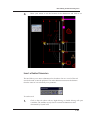
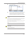
The Tear Away Method
1.
Click and hold the left mouse button on a tool that has a small blue triangle
in the bottom-right corner e.g. click on the “Insert text” button (above).
2.
In this example, a series of tool buttons is displayed in which each button
controls a different option for inserting text in DynaSCAPE Design. This
new display of tool buttons is called a ‘nested’ tool box.
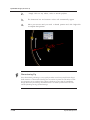
3.
Continue to hold down the left mouse button, and drag the cursor away
from the toolbox. Once you cursor is free from the main toolbox, a new
2.11
DynaSCAPE Design (version 6.4)
toolbox that shows all of the nested tools will follow your cursor. These
tools will all be related to each other in some way.
4.
Release the mouse button to position the new toolbox at a new location.
This uncovered toolbox—and any other created in the same way—has all the
properties of a regular toolbox: it can be resized, minimized or dragged to a new
location. It will also remain open even if its host toolbox is closed.
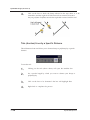
The Scroll Method
Alternatively, you can leave nested tool buttons in their host toolbox and replace the
tool button displayed on top with one selected from the nested group.
2.12
1.
Click and hold a button that has a blue triangle in the lower-right corner:
the nested tool buttons will appear.
2.
Scroll down the list of nested tools.
DynaSCAPE Software
Getting Started
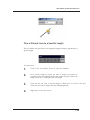
3.
As you scroll down the list, notice that Tool Tips pop up to describe the
function of each nested command button.
4.
Release the mouse button when you find the command you would like to
use.
5.
The list of nested tools collapses and the tool button you selected replaces
the one on top one as the visible tool. This tool will also now be the active
tool.
6.
To end or exit the command, press [Esc] or [Enter]. The tool will no longer
be active but will still appear on top. This button will remain on top of the
nested group until the host toolbox is closed and reopened or until you
repeat the above procedure and change the top button on the group.
2.13
DynaSCAPE Design (version 6.4)
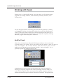
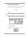
Working with Panels
Floating panels in DynaSCAPE Design work like panels in all Windows-based
programs. For example, toolboxes, such as the Draw [Creation] one below, act as
floating panels.
You can change the location of a floating panel in the Drawing Window by clicking
and dragging its Title Bar; close the panel with the Close control [X]. The Minimize
control [-] rolls up the panel so that only its title bar is displayed. This allows you to
maximize your drawing area without having to close the panel completely. Selecting
Minimize [-] again restores the panel to its full size.
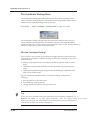
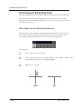
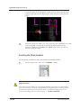
Modifier Panels
Most tools or command icons in DynaSCAPE Design’s toolboxes can be used visually
or freehand; that is, by Clicking on the tool and moving the mouse to draw an object or
entity—for example, a line or circle. However, when you need to specify an exact
length or size for the entity you are drawing, a Modifier panel (or Modifier box) is
generally required. One example is the Line too:
A Modifier gives you more control over the entities you create, for example, by
allowing you to specify properties such as the exact length of a line or radius of a
circle. Tools that require or allow your input of these specific properties will have a
modifier automatically appear when the tool button is clicked on. This applies for all
2.14
DynaSCAPE Software
Getting Started
tools contained in the Quick Start (Qk St), Draw (Drw), Edit (Edit), Dimension (Dim)
and Advanced (Adv) toolboxes. For all other toolboxes, modifiers are accessed by
right-clicking (or double-clicking) on a tool within a toolbox.
Modifier Tip:
Clicking many command or tool buttons allows you to insert an entity visually or freehand.
The Modifier panel that automatically appears allows you to specify an entity’s properties
before you insert it.
Here are some general rules that apply to all Modifier panels:
• Modifier panels are used to affect the current operation only. Any values specified
remain in effect until the command is terminated or until new values are entered.
• In many cases, Modifiers have default values assigned to them. If you wish to
specify a different value for a Modifier, simply click once inside a value field and
enter the new value to override the default one.
• Once you have entered a new value, press spacebar, [Enter] or [Tab] keys on the
keyboard to load the new value into the Modifier.
• Modifier panels do not retain settings from one use to the next. Every time you
open a Modifier panel the default values will be displayed; the Modifier retains no
memory of any values entered in a previous use.
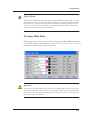
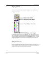
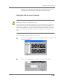
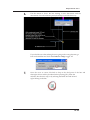
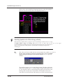
Visibility Toggles
Three control buttons located above the sidebar have been the subject of a few frantic
Help Desk calls, such as, “Where did my Sidebar Folders go?”, and, “I seem to have
lost all my command buttons!”
There are three buttons which control the visibility of most of the button controls
within the program. Accidentally selecting one of these buttons may lead to some
surprising results. Here is what they are used for:
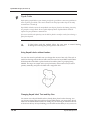
6. The first toggle controls the visibility of the Sidebar Folders. Selecting this toggle
will cause the Sidebar Folders to disappear. Re-selecting the control will cause the
Sidebar Folders to reappear.
2.15
DynaSCAPE Design (version 6.4)
Toggle Tip #1:
This control can be used to temporarily clear the Sidebar Folders from the screen in order to
provide a greater display area for your drawing.
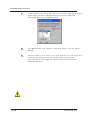
7. The second control converts the Sidebar Folders into a floating panel that can be
positioned anywhere on the Program Window. Re-selecting the control docks the
panel again (returns it to its original location on the left side of the Drawing Window).
2.16
DynaSCAPE Software
Getting Started
Toggle Tip #2:
Converting the Sidebar Folders into a floating panel allows you to take advantage of the
flexibility of panels. The panel can be minimized or moved to increase the available work space.
Note that until docked, the floating panel will appear to be in front of the drawing.
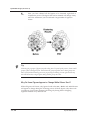
8. The third control toggles the visibility of the Top Button Bar and Toggle Bar. Selecting this control will make these bars disappear; re-selecting the control will make
them reappear.
2.17
DynaSCAPE Design (version 6.4)
Toggle Tip #3:
This control may be used to temporarily clear the Top Button Bar and Toggle Bar from the
screen in order to provide a greater display area for your drawing.
Important Note Regarding Registry Clean-Up Programs
There is a chance that when a registry clean-up program is run that these three toggles, along
with the top toolbars, will be removed. If this happens, the only solution is to uninstall and
reinstall the DynaSCAPE Design program.
2.18
DynaSCAPE Software
Getting Started
The Program Titlebar
The Program Titlebar displays the name and storage location (the file path) of the
currently active file if it has been saved. The words “[Untitled Drawing]” will be
displayed for drawings that have not yet been saved. (See How to Save a Drawing
later in this chapter.)
As in all Windows-based programs, Program Window Controls located on the far
right of the Titlebar allow you to minimize, maximize and close the program window.
Note:
The Close control [X] in the Program Window Titlebar gives the same result as choosing
File | Exit. With either selection, you will be prompted to either save or abandon unsaved
work in any open drawings. (See How to Save a Drawing later in this chapter.)
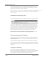
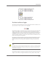
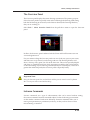
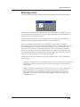
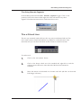
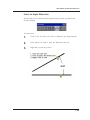
The Prompt Line
Many commands in DynaSCAPE Design require multiple pieces of information to be
provided to perform a task. For example, when drawing a line, you must click the
Drawing Window to indicate the start and end locations of the line; in moving an
entity, you must select the entity and then define the location it is moving from and
the location it is moving to. The Prompt Line displays messages from the program
about what type of action or input is required from you to perform a command.
During any procedure, you can look at the Prompt Line for instructions about how to
proceed through each step. New users will find this feature especially helpful while
learning command procedures.
2.19
DynaSCAPE Design (version 6.4)
When no commands are active (as in the example above), the Prompt Line reads
“DynaSCAPE Professional 2D Computer Aided Design and Drafting”. This Prompt
Line message is referred to as the neutral message.
If the Command Line Interpreter (CLI, see below) is turned off, the Prompt line acts as a
one-line CLI. If the CLI is closed, and no commands are active, the Prompt Line will
read: “Command:”
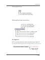
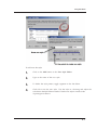
Command Line Interpreter (CLI)
The Command Line Interpreter (CLI) is located just below the Drawing Window.
The CLI is a text-based interface, or communication channel. It provides a textual
record of any command you enter in creating a drawing, including information you
were required to enter, as well as DynaSCAPE Design command prompts. All tasks
that you perform are recorded by the CLI, even if you use panels, buttons, or the
mouse to initiate them. Advanced users can use the CLI to instruct DynaSCAPE
Design to perform tasks by entering commands and data via the keyboard.
Understanding the CLI operation simplifies your overall drawing operations, and
enables you to use some more advanced DynaSCAPE Design features.
Full-Screen and Normal-Sized CLI Display
To open the CLI to full-screen view, right-click inside the text (white background)
area of the CLI. To restore the CLI to normal size, right-click again anywhere within
the CLI text-field area.
Use the scroll bar on the right side of the CLI to review the contents of the CLI log.
The top of the CLI log contains important information about the DynaSCAPE Design
program, including various ways to contact DynaSCAPE Design’s Sales and Support
departments.
Closing the CLI Completely
If you wish to close the CLI completely (to maximize the size of the Drawing
Window), press [Shift] and [Tab] simultaneously. When the CLI is closed, command
line information is displayed in the Prompt Line above the Drawing Window. To
restore (open) the CLI, again press [Shift] and [Tab] simultaneously.
2.20
DynaSCAPE Software
Getting Started
Re-sizing the CLI
It is possible to change the number of lines displayed on the CLI to always show more
information or to increase the size of the drawing page. To change the size of the CLI
press [Shift] and use the up and down arrow keys to increase or decrease the size of the
CLI.
Measuring Tools and the CLI
If you are a new user, you may elect not to use or to take much notice of the CLI.
However, when you use any of the measuring tools in DynaSCAPE Design, the
results of the measurement inquiry are displayed in the CLI. Therefore, to see the
results of any measurement inquiry, use the above-mentioned methods of opening
the CLI.
2.21
DynaSCAPE Design (version 6.4)
A Tour of the Button Bars
Buttons controlling similar functions are grouped together in the Top Button Bar and
Toggle Bar, which will be described in this section.
The Top Button Bar
The File Management Group
The Windows Edit Group
2.22
DynaSCAPE Software
Getting Started
The Drawing Edit Group
The Drawing View Group: Zoom and Scroll
The Toggle Bar
When any of the toggle buttons on the Toggle Bar are turned on, they will display red
letters on a white background; they are turned off when they display black letters on a
gray background. Switch or toggle between the off and on state by pressing the button.
2.23
DynaSCAPE Design (version 6.4)
Toolbox Toggles
All the DynaSCAPE Design toolboxes are controlled using the buttons shown below.
Clicking the DRW button for instance will open the Draw [Creation] toolbox.
Command Toggles
Line and Drawing Environment Toggles
Inference Settings
Drafting with DynaSCAPE is made easier by using a small but powerful tool called an
Inference Engine. As the name suggests, this tool allows the program to infer specific
reference points found on existing objects in a drawing. By referencing these
locations, such as endpoints and midpoints of lines, or origins and quadrants of
circles, you can create accurate arrangements of entities, without having to enter
2.24
DynaSCAPE Software
Getting Started
precise location coordinates. By turning the Inference toggle on, tools and functions
that can use inference will automatically snap to available inference points that it
finds as your cursor gets close to them. The controls that govern Inference can be seen
(or edited) by right-clicking on the Inference toggle and selecting Properties or by
opening the Inference Settings panel (Environment | Inference Settings).
See Chapter 4 for more detailed information about inference and how to use them.
Constraints
The Constraint button, “Select the active constraint mode”, assists various commands
by defining a particular path, angle or direction. This tool effectively duplicates the
function of a T-Square and triangles used when drafting on a drafting board. For
example, with DynaSCAPE Design, you can set constraints to horizontal so that a line
is drawn only horizontally, without your having to set an angle in a Modifier.
Similarly, you could use constraints to force entities to be moved or copied along a set
path or in a fixed direction.
Selecting the Constraint button in the Toggle Bar displays the menu in the diagram
below.
There are four types of constraints:
1.
2.
3.
4.
Ortho (snaps to 90 degree increments)
Horizontal (snaps to 0 degrees, or 180 degrees)
Vertical (snaps to 90 degrees, or 270 degrees)
Polar (snaps to whatever angle is entered under Set Polar)
Angles for the Polar option can be set by selecting Set Polar from the displayed list. By
default, the Polar constraint is set to 45 degrees in DynaSCAPE Design prototype
drawings.
2.25
DynaSCAPE Design (version 6.4)
Set Constraints (make Constraints active) by clicking the Constraint button in the
Toggle Bar and choosing an option from the menu. To turn off constraints, select the
Constraint button and choose “None” from the displayed list.
The Copy Toggle
The Copy toggle has two functions which depend on whether it is turned on or off.
The setting of the Copy toggle is important when using any of the editing tools that
allow objects to be moved or duplicated.
One example would be when using the Move or Copy Objects tool while the Copy
toggle is turned on (red letters on a white background), a copy of the original entity
will be created, which can be repositioned anywhere in the Drawing Window. When
the Copy toggle is turned off (black letters on a gray background), the original entity
can be repositioned anywhere in the Drawing Window, but a duplicate is not created.
The state of the Copy toggle is also confirmed by a pop-up message beside the cursor.
If the Copy toggle is turned on you will see a “Copy” pop-up message. If the Copy
toggle is turned off, you will see the message “Original” beside the cursor.
The Copy toggle is used in conjunction with tools in the Edit [Modify] toolbox and
some of the tools in the Advanced toolbox.
The Sidebar Folders
The sidebar comprises four folder tabs or Sidebar Folders explained below: DynaSCAPE
Design, Figures, Favorites and Imaging. To display the contents of a folder, click once
on its folder tab.
2.26
DynaSCAPE Software
Getting Started
2.27
DynaSCAPE Design (version 6.4)
The DynaSCAPE Sidebar Folder
This is the heart of the DynaSCAPE Design program and is the folder which will be
displayed most often as you draw. The sidebar folders are divided into four different
areas (in yellow on the screen): Commands (command icons), Labeling (labeling
controls), Quotations (cost quotation controls) and the fourth area called Tables
Control, which changes its name (for example, between Layers/Styles/Weights, etc.)
depending on which icon is active beneath it.
2.28
DynaSCAPE Software
Getting Started
Command Icons
Labeling Controls
Quotation/Material List Controls
2.29
DynaSCAPE Design (version 6.4)
Tables and Modes Controls
This area of the DynaSCAPE folder changes its name to one of five different Tables, or
to “Modes”, depending on which icon is active.
Note:
In order to see any content in the Tables or Modes list below the icons, you must have a
drawing open.
In the image to the left, the Layers button has been selected
Layers (covered in Chapter 5) are like transparent sheets of
paper stacked one on top of another: they allow you to give the
same attributes to like entities. For example, all rocks can be
drawn with the same color, line weight and line style, and this
layer can be turned on or off—just like putting on or taking off
a transparent sheet of paper with all the rocks drawn on it—to
keep your drawing area uncluttered, even while working on
complex drawings.
When the Layers button is selected, all of the layers named and
defined for the active drawing, including preloaded layers, are
shown in the Layers List: a scrolling table below the icons. In
the example shown, the Base layer is selected, and so is called
current or active. Since only one layer can be active at a time,
any entities drawn will assume the attributes of the current
layer, in this case, Base.
The Header message, below the icons (the Tables Control) confirms in the example
shown that the Layers List is selected. The message in the yellow bar will change,
depending on which icon (shown in the next diagram) is selected below it, and the
contents of the scrolling table will also change. For example, when the Line Styles icon
is selected, the yellow bar will read, “Styles”, and the scrolling table will display a list
of line styles.
2.30
DynaSCAPE Software
Getting Started
The Select and Revise Toggles
The header message immediately above the scrolling table will show whether or not
you are in Select or Revise mode for lists displayed.
Click the Select toggle, in conjunction with one of the icons for layers, line styles, line
weights, colors or fonts, to choose an attribute from the corresponding list in the
scrolling table. When you select a name in the list, it becomes the active attribute and
is highlighted in blue: new entities created will be assigned to this layer. The Select
and Revise toggles available for use when any of the five Tables are displayed. It is not
needed when using the drawing Modes.
For example, click the Line Styles icon and a list of all currently defined line styles is
displayed. Select a style in the list, and that style becomes the active one. Any new
entities inserted into the drawing will be displayed according to the selected line
style.
Note:
The default setting for Styles, Weights and Display Colors is “By Layer”. Generally speaking,
only advanced users will need to change this setting. Do not change this setting unless you
understand the consequences.
Click the Revise toggle, in conjunction with one of the icons for layers, line styles, line
weights, colors or fonts, to change the attributes of existing objects. Revise mode
2.31
DynaSCAPE Design (version 6.4)
allows you to change the attribute of a previously drafted object (or objects) in your
drawing without having to “erase and replace”. That is, you can leave things drafted
as they were and simply revise any attribute that needs to be changed. For example, a
plant bed accidentally drawn in the “Walkway/Patio” layer can be revised to the
“Plantbed” layer without redrawing the object. Attributes of figures cannot be revised
in this manner, however.
Editing the Active List
The button immediately below the scrolling table is the Edit Active List button.
Pressing that button will bring up an editing panel for whichever list, table, or the
modes is being displayed. The editing panel shows—and allows you to change—the
characteristics of any attribute. For example, you would use the Edit Active List
button while in Layers to change the characteristics of a particular layer or to create a
new layer.
The Figures Sidebar Folder
The Figures Sidebar Folder controls all of the currently active pre-drafted symbols
(called figures) in DynaSCAPE Design. Much of the look and feel of DynaSCAPE
Design drawings is achieved by using figures. Much of the speed, efficiency, and
flexibility of the DynaSCAPE Design drafting process is achieved because the
included figures make drafting a plan quicker and easier.
Figures automatically assume their proper layer and size relative to the drawing scale
when they are inserted into a drawing. Although using the default settings assigned
2.32
DynaSCAPE Software
Getting Started
to a figure makes drafting quicker, you can reset any of the default attributes of a
figure while you insert it into a drawing.
The Library Index gives you access to all the active figure libraries.
Select the Figures Tab to open the Figures folder.
Use the scroll bar to see all the figures (only eight appear at a time).
Figures have associated thumbnail previews: Click on the Thumbnail Image to
select a figure. Once a figure is selected, you will have the option to enter values in
the panel below the figures. By doing so, you can change the size and angle in
which a figure is entered.
• The Figure Name describes the figure and includes a right-click menu (described
below).
• The Reset Button clears any Override Default values.
• Optional Default Overrides can be used to change the default Scale, Rotation,
Width and Height of the selected figure.
•
•
•
•
2.33
DynaSCAPE Design (version 6.4)
The Figure Name Right-Click Menu
If you right-click on a figure’s thumbnail image (or Figure Name) in the figures folder,
the following menu will be displayed.
Selecting the ‘Toggle figure view’ option displays a larger preview version of the
figure, complete with the full name of the figure.
The other option in the right-click menu, “Add to Favorites”, allows you to send a
copy of a frequently used figure to the Favorites Folder. The figure added to the
Favorites folder will still exist in it’s original library, but if the figure is removed from
the original library it will also be removed from the Favorites Folder. Read more
about the Favorites Folder below.
The Favorites Sidebar Folder
When you first install the DynaSCAPE Design program, the Favorites Folder will be
empty. As described in the previous section, you have the option of populating the
Favorites Folder with a copy of any figures that you use frequently. This is done by
right-clicking on the Figure Name (or thumbnail image) of any selected figure in the
figures folder (or in the Figure Manager), and choosing ‘Add to favorites’ from the
displayed options list.
A copy of the figure is added to the Favorites Folder and will retain all of the
attributes previously assigned to the figure.
A right-click option in the Favorites folder, allows you to remove a selected figure
from the folder. Removing a figure from the Favorites Folder will not delete the figure
from the program, because it is only a copy of the original figure.
2.34
DynaSCAPE Software
Getting Started
The Imaging Sidebar Folder
The Imaging Sidebar Folder is home to all the controls related to adding images to
your drawing. Images can be photographs of landscapes you have in your collection,
images of plants from our on-line plant encyclopedia, property surveys, logos, etc.:
almost any images you have can be brought into DynaSCAPE Design. The Imaging
sidebar is broken into two areas: Add Image and Revise.
Add Image
There are three tools under Add Image: two are for inserting images from our on-line
plant encyclopedia and one allows you to add other images from your PC. With the
on-line plant encyclopedia you can insert images either by searching based on the
plant name or by simply clicking on a preexisting label on the drawing, and the online plant encyclopedia will immediately search the database for a photo of that plant.
The other option is to bring in your own images. This tool allows you to locate images
stored on your computer and then insert them onto your drawing page. This method
is commonly used to bring in a scanned property survey, which can be then be scaled
and traced to create an accurate base plan, as well as a company logo.
For detailed instructions for inserting rasters, see Chapter 13 - Working with Raster
Images
There are three tools under Revise: the first two allow you to move, resize and rescale
an image (referred to as a Raster). The move and resize tools are excellent for
repositioning images inserted from the on-line plant database so that they fit better
into the drawing layout. The rescaling option is always used in conjunction with
images entered from your computer, such as property surveys. Using this tool, you
can take any image and, provided you know a distance or length of a line on the
2.35
DynaSCAPE Design (version 6.4)
image, resize the image to match the scale of the prototype you have selected. This
saves valuable time when tracing the information to create the base plan.
The last tool is the Raster Editor, which is what you can use to remove images from
your drawing, or to change the look of your drawing by toggling the visibility of an
image on and off, or to double-check what you are tracing to ensure you have all the
objects included before you remove the raster.
2.36
DynaSCAPE Software
Getting Started
Drawing Navigation
DynaSCAPE Design has seven zoom tools for navigation and for v5.4 a new zoom
command was introduced, making use of a mouse wheel and the [Shift] key.
Zooming Using the Mouse Wheel
The quickest and easiest way to zoom in and out in a drawing is to use the mouse
wheel option. To use this option:
1.
Hold the [Shift] key on your keyboard down
2.
Spin the mouse wheel forward to zoom in
3.
Spin the mouse wheel backward to zoom out.
Note: the location of your mouse cursor will be the centre of the zoom activity.
Practice holding your mouse in different location as you zoom in and out to learn how
you can control the results.
Panning Using the Mouse Wheel
The quickest and easiest way to pan around a drawing is to use the mouse wheel
option. To use this option:
2.37
DynaSCAPE Design (version 6.4)
1.
Hold the [Shift] key on your keyboard down
2.
Press the mouse wheel down and hold
3.
Move your mouse to pan across the drawing page
Note: the location of your mouse cursor will be the centre of the pan activity.
The other Zoom Tools
The seven original zoom tools are found on the top button bar, as described earlier in
this chapter. The following is a description of each and how to use them. Zoom tools
are instream commands, which means you can use them at any time while using
other tools and not affect the process of the other tools.
Zoom Drawing Limits to Best Fit
This zoom tool will fit the drawing limits (the grey dashed line representing the paper
boundary) inside the workspace, regardless of where the geometry is within the
drawing limits.
To use this tool, click on the icon once and DynaSCAPE will fit the drawing limits
inside the workspace.
2.38
DynaSCAPE Software
Getting Started
Restore Previous Zoom Level
The zoom tool works like an undo button for previous zoom activity.
To use this tool, click on the icon once and DynaSCAPE will undo your last zoom
command. You undo as many zoom actions as you have made on the current drawing
since it has been open in the current session. If you are in the middle of a drawing or
editing function, you will need to click on the icon again to activate it again.
Zoom Database Extents to Best Fit
This zoom tool will fit all the geometry that is in your drawing and fit it into the
workspace.
To use this tool, click on the icon once and DynaSCAPE will fit all the geometry that is
in your drawing and fit it into the workspace, even geometry that is outside of the
drawing limits.
Zoom in on the Drawing
This zoom tool allows you to zoom in on a part of the drawing at a system default
increment, one step at a time.
To use this tool, click on the icon once and then click on the drawing where you wish
to zoom in. DynaSCAPE will zoom in once. If you are in the middle of a drawing or
editing function, you will need to click on the icon again to activate it again.
2.39
DynaSCAPE Design (version 6.4)
Zoom the Drawing Out
This zoom tool allows you to zoom out of the drawing at a system default increment,
one step at a time.
To use this tool, click on the icon once and the drawing will immediately zoom out
from the centre of the workspace. If you are in the middle of a drawing or editing
function, you will need to click on the icon again to activate it again.
Scroll the Drawing Using Two Locations
This zoom tool is the closest thing to a pan tool in DynaSCAPE Design.
To use this tool, click on the icon once and then click on the screen. Move your mouse
and you will see a line follow your cursor from the location you clicked on the screen.
If your constraints are turned on you will be limited to their settings. Click on the
screen again in a different location from the first and your drawing will be centered
on the last location clicked. If you are in the middle of a drawing or editing function,
you will need to click on the icon again to activate it again.
Zoom the Drawing using a Window
This tool allows you to zoom in on your drawing using a window drawn with the
mouse.
To use this tool, click on the icon and then click once on the screen. The idea here is to
create a temporary window or rectangle around the area you wish to zoom into. After
your first click, move your mouse in a diagonal direction and you will see a
temporary window or rectangle being drawn. Click again and DynaSCAPE will zoom
the drawing to best fit the geometry, that is in this rectangle, inside the workspace.
2.40
DynaSCAPE Software
Getting Started
Opening and Saving a Drawing Exercise:
This quick exercise will walk you through creating your first DynaSCAPE Design
drawing:
1.
Click on the New Drawing button and select the v6.0: Imp (Landscape): A8.5.x11 - SCALE 1"=04' prototype.
2.
Select the Accessories layer from the Layers List on the DynaSCAPE
Design tab: the layer will be highlighted in blue.
3.
If the Draw [Creation] toolbox (Draw toolbox) is not open, click on the
DRW toggle located under the New Drawing button. From the Draw
toolbox, right-click on the Rectangle tool.
4.
Enter a width of 10’ and a height of 5’, and be sure to press the [spacebar]
after entering the final value.
5.
On the Drawing Window, Click where you want the top-left corner of the
rectangle to be, and note that the prompt line is directing you to “Select the
first corner of the rectangle”.
6.
Once the first corner is located you will need to set the direction of the
rectangle. Move your mouse until the rectangle is in the position you want
and Click.
7.
Press [Esc] to exit the command.
Congratulations! You have just created your first DynaSCAPE Design drawing. The
next section will walk you through saving a drawing.
How to Save a Drawing
When you first open a new prototype drawing and begin drafting a plan, the work
you are doing is not being safely stored in your computer’s storage system until you
actively save it. Until you save a plan (give it a file name and a storage location), it
exists only as a series of DynaSCAPE Design commands (temporarily held) in your
computer’s RAM memory. Because of this, your work is vulnerable to being lost if
there are any glitches in your computer environment (software or hardware
problems). You should save a new drawing as soon as it is practical to do so.
2.41
DynaSCAPE Design (version 6.4)
Important:
Never save a drawing over a network or to any removable storage
device. Saving this way may result in a corrupted drawing file.
Always save to your local computer and then copy the drawing file
to the network or removable storage device.
DynaSCAPE Design provides the standard Windows utilities and routines for saving
your work. You can initiate the Save command in any one of three ways:
1. Manually save the Active Drawing
2. Automatically save the Active Drawing using the Autosave option
3. And finally, the ‘Save Drawing?’ panel will be prompted by either closing the
active drawing, closing all open drawings, or by closing (exiting) DynaSCAPE
Design.
Saving Over a Network Not Recommended
Do not save drawings over a network. This may result in unrecoverable corrupted
drawing files. Save to a your local computer and then copy the drawing file to the
network.
Saving to a Removable Storage Device is Unsafe
Do not save drawings to a removable storage device. This may result in unrecoverable
corrupted drawing files. Save to a your local computer and then copy the drawing file
to the removable storage device.
Saving a Drawing Manually
You can manually initiate the Save command by either selecting the save button
,
2.42
DynaSCAPE Software
Getting Started
or by selecting File | Save from the pull-down menu.
Note:
The keyboard shortcut for the Save command is [Ctrl] + [S].
If you have not previously saved your drawing, the “Save Drawing As” panel will
open; if you have previously saved your drawing, the file will be updated to reflect all
changes made since the previous save.
Choose (or create) a storage location (folder), name your drawing, and select the Save
button in the lower-right corner of the panel to complete the Save routine.
Important:
DynaSCAPE has a maximum file path length of 128 characters. This includes all the folders in
the path. e.g. C:\Documents and Settings\[computer name]\My Documents\My
Drawings\Drawings 2008\Completed\Smith Residence is a file path with 102
characters. This means that if you wanted to have a file name longer than 26 characters, the
drawing cannot be saved. It is recommended to keep folder and files names short.
2.43
DynaSCAPE Design (version 6.4)
Saving a Drawing Automatically: The Autosave Command
To set up the Autosave command, choose Environment | Systems Settings from the
pull-down menu.
When DynaSCAPE Design is first installed the default will be set at “0” (zero
minutes). Setting an new value (greater than zero) will activate the Autosave
command. For example, if you enter a new value of 10 into the panel, the Save
command will be automatically initiated after 10 minutes have passed and will repeat
at 10-minute intervals for as long as a drawing is active (open).
Note:
Setting an Autosave interval of less than 10 minutes is not recommended when you are just
learning to use the software. One of the most useful features of DynaSCAPE Design is the
unlimited Undo and Redo command. But you cannot Undo past the last Save command, so if
you have the Autosave interval set too low, you will not be able to take full advantage of Undo
while you are learning to use the software.
When you open a new Prototype Drawing, the Autosave interval begins counting
down. When the first interval elapses (the minutes set as the Autosave interval), you
will be prompted to choose a name and storage location for your work. After a name
and storage location are set, the Autosave command will simply re-save the drawing
automatically at the Autosave interval for as long as the drawing is active.
2.44
DynaSCAPE Software
Getting Started
Note:
Autosave is a Global Setting, meaning that all active drawings will be controlled by this
setting.
Initiating the Save Command by Exiting a Drawing (or the Program)
As stated above, closing a drawing (all drawings) or exiting the DynaSCAPE Design
program will activate the Save routine if you have made any changes in the
drawing(s) since the last time that you saved.
In any case, when you close a drawing (or drawings) the following panel will be
displayed.
• Selecting the Save button will update the drawing file to reflect all recent changes
or will cause the “Save Drawing As” panel to open if the drawing has not been
previously saved.
• If you have no additional significant work (worth saving) in the drawing, select the
Abandon button: the drawing will close, and the drawing file will revert to the previously saved version. Don’t worry: the Drawing file will not be deleted by selecting Abandon.
• Selecting “Cancel” (or selecting the [X] control), will cancel the Save Changes procedure and you will return to the drawing.
How to Close a Drawing
Use any of these three methods to close the active drawing:
• Select the Close button (or press File | Close All from the File pull-down menu).
• Select the [X] in the upper-right corner of the window.
• Type the [Ctrl] + [U] keyboard shortcut for the Close command.
Once you have initiated the Close command (and if you have performed at least one
command in the drawing), you will be prompted to Save or Abandon any recent
changes made in the drawing.
2.45
DynaSCAPE Design (version 6.4)
“Save” will save all your work done until the point in which you closed the drawing:
this will likely the option you select. “Cancel” will bring you back to the design to
continue working. “Abandon” is generally only used if you have not performed any
additional work (worth saving) in the drawing.
Note:
Selecting the Abandon option in the Save Changes panel, does nothing more dire than ignore
your most recent work on a drawing (any commands issued since you last saved); if you choose
the Abandon option, your drawing will not be deleted.
Exiting DynaSCAPE Design
Exiting DynaSCAPE Design can be done either by using the [X] in the upper-right
corner of the screen or by choosing File | Exit on the pull down menu.
2.46
DynaSCAPE Software
3
Opening a DynaSCAPE
Drawing
Topics covered in this chapter:
Opening existing and sample DynaSCAPE Design drawings
Working with multiple drawings
Opening a drawing from older versions of DynaSCAPE Design
Converting a 4.x Drawing to 5.x or newer
Managing DynaSCAPE Design files
3.1
DynaSCAPE Design (version 6.4)
Opening a DynaSCAPE Drawing
Pressing the second icon (“Open an existing drawing”) in the Top Button Bar will
display the Open Drawing panel, which will allow you to open any previously saved
DynaSCAPE Design drawing files. Although the panel will display all of the folders
found on your computer, it will show only DynaSCAPE Design files—those with the
*.dpd file extension. Open drawings by selecting a file and clicking the Open button
in the lower-right corner of the panel, or double-click the file name in the directory. If
you do not see the file extensions, you may need to change your folder settings using
the procedure described later in this chapter. (See section “Resetting Windows
Explorer to Show File Extensions”.)
Opening a DynaSCAPE Design Sample Drawing
Use the Open Drawing panel to find and open the sample drawings we provide. Find
them in the Drawing Samples folder at C:\Program Files(x86)\DynaSCAPE\Design
\Samples (assuming that the DynaSCAPE software was installed on the C:\ drive of
your computer as suggested.)
Important Note:
Depending on your version of DynaSCAPE Design, you may not see exactly the same list of
sample drawings shown in the images below, but the sample drawings will be in the same
folder location. Some versions of DynaSCAPE Design may not have this folder.
3.2
DynaSCAPE Software
Opening a DynaSCAPE Drawing
There are a number of sample drawings stored in the Samples folder:
Working with Multiple Drawings
DynaSCAPE Design gives you the option of opening multiple drawings in the
Drawing Window. To see the various options for the display of multiple drawings,
select the Window pull-down menu. (See Chapter 4 for more information on the
Window pull-down menu.)
Setting the Active Drawing
You may open as many drawings as you like in DynaSCAPE Design; however, only
the active drawing will be the target for the commands you issue. The active drawing
will have a bright blue title bar; any other drawings will have a dim blue title bar.
There are three ways to make a drawing active (when multiple drawings are open):
1. Click on any part of the drawing in the Drawing Window
2. Select the drawing to activate from the list displayed at the bottom of the Window
menu
3. Choose Window | Previous, or hold [Ctrl] and press [W] as a keyboard shortcut
for Previous file. Or choose Window | Next, or hold [Ctrl + Shift] and press [W] as
a keyboard shortcut for Next file.
Note:
We strongly advise that only one drawing be open and active at a time. Having more than one
drawing open, especially different versions of the same drawing, can be confusing, and can lead
to accidental overwriting or loss of an entire drawing. DynaSCAPE can also become unstable
if more than one drawing is open at a time. DynaSCAPE’s drawing recovery can only recover
one drawing in the case of a power failure or crash.
3.3
DynaSCAPE Design (version 6.4)
Opening a Version 2.0/2.5 (Legacy) Drawing
or Project Bundle
Drawings that have been created and saved in an older version of DynaSCAPE (2.x)
will have the file extension (*.dpd) or ((*.prw).
To Import an older (legacy) version of a DynaSCAPE drawing (version 2.0 or version
2.5), select the pull-down menu File | Import | DynaSCAPE 2.5 Drawing..., or
File | Import | DynaSCAPE 2.5 Project Bundle... to open the Select Legacy
DynaSCAPE drawing file panel.
Important Note:
If you cannot see any file extensions for your drawings you may need to change the view of
your files by clicking on the “Open an existing drawing” icon | View Menu icon (on the far
right of the Open Drawing Panel) | Details. If you still cannot see the file extensions, follow
the instructions in the section of this chapter called “Resetting Windows Explorer to Show File
Extensions” (ahead).
3.4
DynaSCAPE Software
Opening a DynaSCAPE Drawing
Notice how this file management panel displays only (*.dpd) files if you are
importing a drawing, and (*.prw’) files if you are importing a project bundle.
To open the file you want to import, select the file from the display list, then select the
Open button (or simply double-click the file name).
If Your Drawing Will Not Open
If you are using the Open command to view a (.dpd) file, and DynaSCAPE Design
cannot display the drawing (the drawing won’t open), then you are likely trying to
open a file from an older version of DynaSCAPE Design. Try using the Import method
described above.
If you are using the Import method to view a (*.dpd) file and get the an error message
like the one below, your drawing was most likely created using a more current
version of the DynaSCAPE Design software. To open this drawing file, use the
standard method described at the beginning of this chapter.
Deleting Unneeded Project Management Files
After upgrading to DynaSCAPE Design from an older version of the program some
files in your computer (where you stored your previous drawing files) become
unnecessary. For example, files with a [*.prt] extension or [*bmp] extension used
under the old Project Management filing system can be deleted.
Note:
The deleting of old project management files is not required, but deleting them will free up disk
space. Caution: Be careful not to delete old files before you’ve imported and saved the drawing
files in the latest DynaSCAPE Design format.
3.5
DynaSCAPE Design (version 6.4)
Use Windows Explorer to find and delete these files, for example, in folders with
automatically generated names such as “Designs 2002”. The name of a [*.prt] file
always matched the name of the project folder; that is, if you had a “Smith” folder in
“Designs 2002”, you would have had a [Smith.prt] file there, as well. All [*.prt] files
can be deleted, but be careful not to delete the old Project folders before you’ve
imported and saved the drawing files in the latest DynaSCAPE Design format.
3.6
DynaSCAPE Software
Opening a DynaSCAPE Drawing
Converting a 4.x Drawing to 5.x or Newer
DynaSCAPE version 5 (and newer) has a different layer list than version 4 and
previous versions. This also means that the Modes have also been changed to match
the new layer list in version 5 (and newer). In addition, version 5 (and newer) has
rebuilt library figures that contain the new layers. 4.x drawings can be opened in
version 5 (and newer), but it is important to know the difference between the two
versions, especially if you wish to continue working with the version 4.x drawing.
How Do I Know if My Drawing is Version 4.x or Version 5.x
and Newer?
If you look at the layer list of the drawing in question, the first clue will be that the
first and third layers have changed (among others). If the first layer is Detail and the
third layer is Driveway, your drawing is not a version 5.x (or newer) drawing. In
version 5 (and newer) the Detail layer has been changed to Temp (see image below):
3.7
DynaSCAPE Design (version 6.4)
Can I Convert a Pre-Version 4.x Drawing to 5.x or Newer?
Yes, you can convert any older version drawings to version 5.x (and newer).
However, pre-version 3x drawings have softscape and hardscape labels from
different estimating system and as a result they will not be recognized to create a
Material List or Plant Schedule.
Version 2.5 Project Bundles (.PRW) will first need to be imported into DynaSCAPE
version 5 (follow the steps outlined earlier in this chapter).
Why Do I Need to Convert my Drawings to 5.x or Newer?
Any version 4.x drawing will open in version 5, allowing you to view, navigate and
print, but it is not recommended to edit or work on the 4.x drawing until it has been
converted to 5.x (and newer) format.
What are the Main Differences Between a 4.x and a 5.x and Newer
Drawing?
1. Layers - version 5 has a new layer list with additional layers and a reorganization
of the layers into a more intuitive order
2. Modes - version 5 has a new set of modes designed to work with the new layer list
3. Figures - version 5 library figures all contain the new layers
4. Softscape Labels - version 5 uses a new format of plant labels that correspond
with the properties of the plant information found in the new, Horticopia based
Online Plant Database (plant types, leaf colors, bloom colors etc.)
5. Hardscape Labels - version 5 uses a new Design Label format that uses a descriptive type of label instead of a material
What Tasks Can I Perform Without Converting to 5.x and Newer?
With a 4.x drawing opened in version 5 (or newer), you can:
• View and navigate
• Print and Save-as PDF or JPEG
• Erase and edit geometry
Tasks Not Recommended Prior to Converting to 5.x and Newer
The following tasks are not recommended to undertake prior to converting a 4.x
drawing to 5.x (and newer) format:
3.8
DynaSCAPE Software
Opening a DynaSCAPE Drawing
• Do not add library figures - version 5 (and newer) library figure use the new layers
and will not show up correctly on an unconverted drawing
• Do not use Modes - version 5 (and newer) modes will turn off different layers than
version 4 and this will cause the version 4 drawing to view incorrectly
• Do not create a Material List - version 5 (and newer) will not recognize version 4
Softscape or Hardscape labels that have not been converted to create a Material
List
• Do not create a Plant Schedule - version 5 (and newer) will not recognize version 4
Softscape labels that have not been converted to create a Plant Schedule
How to Convert a Drawing to 5.x and Newer Format
To convert a version 4.x drawing to version 5.x (and newer), follow these steps:
1.
Open the version 4.x (or 3x) drawing
2.
From the File menu, select Convert > version 4.x drawing to 5.x Format
3.
A message box will appear warning you that this conversion cannot be
undone. There is not need to worry here because you will be saving the
3.9
DynaSCAPE Design (version 6.4)
converted drawing as a new one, allowing you to keep the original
drawing as 4.x drawing in the case that you may need it.
4.
Click Yes. The process will go very quickly and a message box will appear
to say the conversion is complete. It also says you changes will be saved to
a new file. This means that you will need to click Save and save the
drawing under a new. It is recommended that you save the drawing under
a name that will help you recognize that the drawing has been converted to
version 5.x (and newer) (e.g. add ‘5.x’ at the end of the name).
Note: The process will turn all your layers on to show that they all have
been converted. You can now use any of the modes to view the items you
wish to see.
5.
Click Ok and then Save the drawing under a new name.
Limitations of Converted Drawings
Once a drawing is converted to the new version you will be able to edit and print as
usual. You will also be able to perform functions such as creating Material Lists in
Word or Excel, generate a Plant Schedule, import into DS|Quote or DS|Manage and
the new DS|Manage360 (Manage Website). However, there are some limitations you
need to be aware of:
3.10
DynaSCAPE Software
Opening a DynaSCAPE Drawing
Creating Material Lists in Word or Excel
You can create material lists without prices. Prices were not embedded into 3.x and 4.x
drawings and therefore cannot be extracted for this function.
Generating Plant Schedules
Plant Schedules can be generated but the old plants types will not be recognized. All
plants will be placed under a Other Plants heading.
Generate a Plant Picture Catalogue
Since v4.x drawings are linked to the old Plant Encyclopedia, plant picture catalogues
will not be able to be created after conversion to 5.x (and newer)
Import into DS|Quote or DS|Manage for Quotation
All links to materials and kits in DS|Quote or DS|Mange will be maintained, allowing
you to generate quotes and material lists in Quote or Mange. DS|Quote or DS|Mange
will need to be update to the new Design 5.x (and newer) compatible version in order
to perform this function.
Import into the New DS|Manage (web version) for Quotation
All links to materials and kits in DS|Quote or DS|Mange will be maintained, allowing
you to generate quotes and material lists in the new DS|Manage (web version).
3.11
DynaSCAPE Design (version 6.4)
File Management
How DynaSCAPE File Management Differs from Older
Versions
If you are a first-time DynaSCAPE Design user (and you are not likely to receive any
drawing files saved in a previous version), you can ignore this section of the chapter.
And, because we showed you how to save your work in Chapter 1, you’re ready to go.
If, on the other hand, you are upgrading to DynaSCAPE Design, or have received a
[*.dpd] file in a previous version of DynaSCAPE Design, read on.
DynaSCAPE uses standard Windows file management for the storage of drawing
files. This system is different from earlier versions of DynaSCAPE Design that used a
file management model called “Project Management”.
With DynaSCAPE Design there is no longer any Project Management panel, or Project
Management functionality. This change has only one small negative impact: there is
no more drawing preview window.
Switching to a standard file management system means the following:
1. A dramatically simpler filing system.
2. No need to create a Project Name when you save a drawing.
3. No need for “Project Bundling”, so moving drawings is easier.
Saving Old Drawing Files
In the next image, we show an example of the old model of storing a single drawing.
A project “Smith” has two files associated with it: Smith.dpd and Smith.bmp. If you
delete Smith before importing and saving the *.dpd file, the drawing will be lost.
3.12
DynaSCAPE Software
Opening a DynaSCAPE Drawing
Resetting Windows Explorer to Show File Extensions
The following pages examine a number of file management issues. In order for you to
follow the text and instructions ahead, you may need to reset one of the controls in
Windows Explorer so that you can see file name extensions. Changing the visibility of
file name extensions will not adversely affect the operation of any program in your
computer, so there is no need to reverse the changes we make to the settings.
In Windows XP:
Open Windows Explorer by right-clicking on the Windows Start button and choosing
Explore, or click the Windows Explorer icon.
From the Tools menu (at the top of the Windows Explorer panel), select Folder
Options to open the Folder Options panel.
In Windows Vista and Windows 7:
Open Windows Explorer by right-clicking on the Windows Start button and choosing
Explore, or click the Windows Explorer icon.
Click on the Organize menu and choose Folder and Search Options to open the
Folder Options panel.
3.13
DynaSCAPE Design (version 6.4)
Select the View tab in the panel (as above) to display the list of view settings.
Then do the following:
3.14
6.
Uncheck the “Hide extensions for known file types” toggle (shown above).
7.
Select the Apply button in the lower-right corner of the panel.
8.
Select the Apply to All Folders button near the top of the panel.
9.
A Folder Views panel will pop up and ask you to confirm these changes:
select the Yes button.
10.
Select OK in the Folder Options panel, and close Windows Explorer.
DynaSCAPE Software
Opening a DynaSCAPE Drawing
Backing Up and Protecting Your Work
Backing up your drawing files is highly recommended because computer
environments, hardware, operating systems, software, and operators are not 100%
dependable.
Here are a number of ways to back up your files:
1. Copy your completed drawing files to a back-up folder within your own computer. This is the quickest way of protecting your files. Using a second hard drive
in your computer as the back-up storage drive will protect you if your main hard
drive fails.
2. Back-up files on a removable disk drive or tape drive.
3. Burn your files onto a CD or DVD. (Note: You will not be able to use a CDRW in
the same way as a disk or tape drive. Use these storage devices only for completed
work that is not likely to require editing)
3.15
DynaSCAPE Design (version 6.4)
Program Resources
DynaSCAPE Design ships with a number of useful resource files. The following files
or folders can be found in the C:\Program Files\DynaSCAPE\Design\Resource
folder:
• The Drawing Samples folder contains sample drawing files that show some of the
design possibilities that DynaSCAPE offers.
• The Resource\Tutorial folder contains the drawings used in the Tutorial Chapters
in this guide as well as sample lot plans that can be used for practicing tracing rasters.
Additional Resources
In addition to the resources above, the Resource folder also holds a number of graphic
image files with the [*jpg] extension that may be useful. These include:
• Image files of a scanned property survey to practice tracing for base plans
• A LOTPLAN.jpg file with the measurements to be used in the Tutorial chapter in
this guide
• Images of the plants used in the Tutorial
3.16
DynaSCAPE Software
4
Menus, Settings and
Controls
Topics covered in this chapter:
Using the DynaSCAPE pull-down menus and their options
Using the Inference Engine (Snaps)
Changing the drawing settings and defaults
Using On-line Help
DynaSCAPE Design contains many different tools, toolbars and menus. This chapter will
describe the various pull-down menus and the options they provide.
4.1
DynaSCAPE Design (version 6.4)
Pull-Down Menus
The pull-down menus Edit, Window and Help will be familiar to any Windows user.
The File menu is also shared by most Windows applications; however, in
DynaSCAPE Design it contains a few DynaSCAPE-specific commands.
The other four pull-down menus are unique to DynaSCAPE Design. In the pages that
follow, we will explore menu commands of greatest importance to a new
DynaSCAPE Design users. Information on other commands can be found by selecting
the command of interest and [F1] for on-line Help.
4.2
DynaSCAPE Software
Menus, Settings and Controls
The Environment Menu
The Environment menu contains all of the basic controls that affect the work
environment in DynaSCAPE Design and is one of the most important menus to be
familiar with.
Global Versus Active Drawing Control Settings
Three of the controls in the Environment menu (System Settings, Command Alias
and Library Properties) are global control settings, meaning they control programwide aspects of DynaSCAPE Design.
The remaining controls in this menu apply only to the active drawing, which is
currently open. This means that changes in these controls and settings will only alter
the environment of the drawing in which they are changed, even though many
drawings may be open.
Changing Settings on the Fly
Forgetting to change a setting at the beginning of a drafting session isn’t a problem.
DynaSCAPE Design’s drawing environment can be changed at any stage of the
drafting process without your having to abandon your work. However, line
thicknesses, font sizes and hatch scale are pre-set by the prototype and become the
default settings for your drawing.
Using the Environment menu to change active drawing scale in mid-stream, can
greatly change how new lines, text and hatches appear; lines, hatches and text may be
too large, small, thick or thin, so manual adjustment of these variables is necessary.
Similarly, the Environment menu lets you change to a new sheet size, but in doing so
your drawing may need to be repositioned in respect to the drawing limits.
4.3
DynaSCAPE Design (version 6.4)
Important:
Care should be taken when making global changes. Save a separate version of your work prior
to making major changes to the environment. By doing so, you can quickly return to the
original version if necessary.
System Settings
The System Settings panel consists of four tabs, of which the User Profile tab and the
Environment tab are most commonly used. Open the Systems Settings panel by
using the pull-down menu to navigate to Environment | System Settings.
The User Profile Tab
Selecting the User Profile tab gives you access to your registration information as well
as your name and company name. The permissions settings here are locked and
cannot be changed.
The Environment Tab: The Autosave Setting
Selecting the Environment tab in the System Settings panel gives you access to the
Autosave command setting.
4.4
DynaSCAPE Software
Menus, Settings and Controls
Important Note
System Settings are Global in nature so all active drawings will be affected by changes made.
Command Aliases and Keyboard Shortcuts
What is a Command Alias?
A Command Alias is a user-defined keyboard shortcut that:
• Makes it possible to create keyboard shortcuts that create the text for the Insert
Text, Insert Text with a Leader, Revise Text, and Revise Text with a Leader tools.
This will be covered in the chapter titled Basic Drawing Tools.
• Activates a pre-saved auto-run sequence (macro) consisting of one or more commands.
The Command Alias tool is found by selecting Environment | Command Alias.
Example Command Aliases in DynaSCAPE Design
Refer to the examples below to help create your own command aliases, or add them to
your own list. More examples regarding editing text can be found in the chapter titled
Deleting and Revising Entities.
TABLE 1. Example
Command Aliases
Shortcut
Code
Description
Z
^iZOOM DRAWING WINDOW ^#
Turns on the Zoom the Drawing
using a Window tool.
ZZ
^iZOOM DRAWING LIMITS ^r
Zooms the drawing to the drawing
limits.
ZD
^iZOOM DRAWING EXTENTS ^r
Zooms the drawing to display all
drawn objects.
PAN
^iSCROLL DRAWING VECTOR ^r
Activates the scroll (pan) tool
4.5
DynaSCAPE Design (version 6.4)
TABLE 1. Example
4.6
Command Aliases
Shortcut
Code
Description
CO
^iTRANSLATE ENTITY SELECT
TRANSFORMATION COPY ^#
Turns on the Move/Copy tool with
Copy on
CF
^iTRANSLATE ENTITY SELECT
TRANSFORMATION
ORIGINAL^#
Turns on the Move/Copy tool with
Copy off
R
^iREPAINT ^r
Repaints the drawing page.
D
^iDELETE ENTITY ^#
Deletes any selected objects.
L
^iINSERT LINE LOCATION ^#
Turns on the Insert Line tool.
LL
^iINSERT LINE LOCATION
Length ^#
Turns on the Insert Line tool and
waits for a length to be entered.
C
^iINSERT CIRLCE LOCATION ^#
Activates the circle tool
CC
^iINSERT CIRLCE LOCATION
Radius ^#
Activates the circle tool and waits
for the radius to be entered
P
^iINSERT POLYLINE LOCATION
^#
Activates the Polyline tool
PC
^iINSERT POLYLINE LOCATION
Smooth Autobulge SELECT
CONSTRAINT OFF ^#
Activates the Polyline tool with
Smooth Polyline selected and
constraints turned to None
PCA
^iINSERT POLYLINE LOCATION
Smooth Autobulge DefTAngle
SELECT CONSTRAINT OFF ^#
Activates the Polyline tool with
Smooth Polyline selected and
constraints turned to None and
waiting for you to define the start
angle
RFN
^iREVISE ENTITY ATTRIBUTES
Fill On ^#
Turns on the fill of selected lines
and curves.
RFO
^iREVISE ENTITY ATTRIBUTES
Fill Off ^#
Allows you to select lines to turn
the fill property Off
ROB
^iREVISE ENTITY ATTRIBUTES
Output 10 ^#
Allows you to select objects to
revise their output color to black
DynaSCAPE Software
Menus, Settings and Controls
Creating a New Command Alias
Note
Creating a new command alias is recommended for advanced DynaSCAPE Design users. New
users may wish to skip to the next section and tackle this later.
The Command Alias tool is found by selecting Environment | Command Alias.
To create a new command alias:
1.
Click the Add button in the Alias Settings panel.
2.
Enter a shortcut in the window that appears. For example, a shortcut to set
the Output Color to Black might be OB. Click OK to add the shortcut. No
two shortcuts can be the same.
4.7
DynaSCAPE Design (version 6.4)
3.
Enter the new command code (see the Command Alias Syntax section
below.
4.
Click OK to save the command alias. To use the command alias while
drawing, type the shortcut followed by [Space] or [Enter].
Command Alias Syntax
Creating a new command alias requires entering the code to execute a command in a
way that DynaSCAPE Design understands. Fortunately, most commands and options
in DynaSCAPE Design are duplicated in the CLI. For example, right-clicking the
Insert Line tool and entering 10’ in the Length field and 30 in the Angle field in the
modifier panel displays INSERT LINE LOCATION: [2D LOCATION]Length 10 Angle 30
after the prompt in the CLI. (: [2D LOCATION] is merely informational and can be
ignored.)
In addition to the command itself, a command alias requires a prefix, ^i, and a suffix,
either [Space]^# or [Space]^r. The suffix depends on whether more input is required. If,
as with INSERT LINE LOCATION, the user must click on the drawing or make some
other input, the command alias should include the [Space]^# code. Otherwise, as with
REPAINT, the command should end with [Space]^r.
If a command requires separate inputs for different options, use the [space]^# code
after each option.
Refer to the table presented earlier on in this section for examples.
4.8
DynaSCAPE Software
Menus, Settings and Controls
The Drawing Page Settings
From the pull-down menu, select Environment | Drawing Page to open the Drawing
Page Settings panel. This panel can also be opened using a keyboard shortcut: hold
the [CTRL] key and press [H].
Important Note
DynaSCAPE Design allows you to change any or all of the default settings in Environment |
Drawing Page at any time during a drafting session. For instance, you may change a
drawing that was originally set up in metric units to imperial units (or vise versa), which can
be very useful if you must work with data in both units at the base-planning stage, drafting
stage, or estimating phase of a landscape plan.
Changing the Sheet Size (Paper Size) of a Drawing
The Sheet Size (paper size) tab in the Drawing Page Settings panel highlights the
current size of the drawing sheet in the Sheet Size list. If you wish to change the sheet
size simply use the scroll bar on the right side of the list to find an alternative size,
select the new size, and then select [OK] to complete the change and close the panel.
Changing the Scale of a Drawing
The Scale tab in the Drawing Page Settings panel shows the current drawing scale.
You may change the active drawing scale simply by entering a new value (or editing
4.9
DynaSCAPE Design (version 6.4)
the current value) in the Scale box and selecting [OK] to complete the change and
close the panel.
Important Note
The drawing scale may be entered either as a ratio (for example, 1:50), or as an imperial scale
(for example, 1” = 4’). Be sure to include the foot and inch symbols when entering new scale
values.
Viewing or Editing the Default Measuring Units
The Units tab in the Drawing Page Settings panel allows you to view or edit the
default units of measure in the currently active drawing, which is useful if you need
to switch between imperial and metric measurements when working with property
surveys or architectural drawings.
4.10
DynaSCAPE Software
Menus, Settings and Controls
In the example above, the default measuring unit is “Feet”. This means that when a
numeric value is required (when entering the length of a line, for instance) the
software will interpret the numbers entered as feet.
Viewing and Editing the Data Format Settings
From the pull-down menu, select Environment | Data Format to open the Data
Format Settings panel (below).
In the panel shown, by selecting Architectural, feet and inches are chosen to edit and
display distance data. Although this format may at first seem like the only format for
4.11
DynaSCAPE Design (version 6.4)
distance (length) data when using Imperial measure, there is Engineering scale, which
measures distances in decimal feet, not feet and inches (e.g. 10 Scale means one-inch
equals 10 feet) and Decimal, used for metric drawings.
For a complete explanation of all of the formats for distance and angle, select [Help] in
the lower-right corner of the panel or press [F1].
Entering Lengths with Feet Only
When using the Architectural format entering a length of only feet does not require
you to use the symbol for feet. Just type in the number of feet and press [Enter] or
[Space]
E.g. for 6’-0”, Type 6 and press [Enter] or [Spacebar]
Entering Lengths with Feet and Inches
When using the Architectural format and entering a compound measurement
involving feet and inches, it is not necessary to type the symbol for inches (quotation
mark) when the default measuring unit is set to ‘Feet’. The software assumes that the
value following the symbol for feet (an apostrophe) represents inches. You will have
to supply the symbol for feet, if the default measuring unit is set to inches (or convert
the compound value entirely to inches).
e.g. for 5’-3” enter 5, foot symbol (‘) and then 3 and press [Enter] or [Spacebar
If using decimals instead of the foot symbol, DynaSCAPE will assume any number
before the decimal is for feet and any numbers after the decimal is a percentage of a
foot and will be converted to inches.
e.g. for 1’-6” enter ‘1’ decimal ‘5’ and press [Enter] or [Spacebar
If the default measuring unit is set to Decimal, both the feet and inch symbols must be
used or the software will assume the value is in decimals. It is possible to change your
default units from Imperial to Metric and back again. This is often done when creating
a base plan using a metric property survey, for a design that will be drawn in feet and
inches.
Entering Lengths with Feet, Inches and Fractions
Since most users will employ the Architectural format the following table shows the
proper syntax for entering a fractional length into the system:‘
4.12
DynaSCAPE Software
Menus, Settings and Controls
Grid, Axis and Snap Tool Settings
The default settings for the visibility of the reference grids available in DynaSCAPE
Design, as well as the snap locations, can be found in the pull-down menu
Environment | Drawing Tools... These can be used to show a visible grid on the
drawing page similar to graph paper in addition to allowing you to snap your line to
this grid. These can be used to assist in the drawing process.
if
4.13
DynaSCAPE Design (version 6.4)
Grid— The grid is a series of dots that are placed at set intervals on the screen when
turned on.
Axis—The axis acts the same as graph paper would when drawing by hand. When
turned on it will place grid lines on the screen at the spacing set by the panel.
4.14
DynaSCAPE Software
Menus, Settings and Controls
Snap—The snap works much like the inference settings, snapping to the grid/axis for
placement of lines, figures and other entities.
Changing the Color of the Grid and Axis
To change the color of the Grid or Axis, click on the Misc. tab in the Tool Settings
panel. Click on the tools button in the middle of the panel and change the color.
Changing to a color like dark grey will be less visually obstructive than a lighter color.
Background Color of the Drawing Page
To access the controls for the background page color select Environment | Page
Color.
4.15
DynaSCAPE Design (version 6.4)
The default background color for the Drawing Window is black in all DynaSCAPE
Design Prototype drawings, a color many find easy on the eyes and one that provides
the best contrast for other screen colors. However, you have the option to change the
background color to any of the 256 colors. This option is not a global setting and will
only effect the current drawing.
Changing the Background Color When Using Color Figures
Most DynaSCAPE Design users print their work in a simple, black-on-white format.
DynaSCAPE provides the ability to print in color, and Color Figure Libraries are
provided. If you would like to use the Color Figure Libraries, you may wish to reset
the background color of the Drawing Window to white. This way, you will see the
elements on your screen exactly as they will appear when printed on white paper.
To change the Drawing Window background color, click the Background Color
button in the Page Color panel to open the Color Selector panel.
Using this panel, you can reset the background color of the Drawing Window to any
one of 256 colors. To change the background color of the Drawing Window to white,
for example, scroll to the bottom of the Custom Color List. Select “White”, and then
4.16
DynaSCAPE Software
Menus, Settings and Controls
OK. For an in-depth tour on using the Color Selector, select [Help] in the lower-right
corner of the panel or press [F1].
Printing With Screen Colors
When printing, if you would like to use the on-screen colors (Display) as the output
color (Output), be sure to select the option “Print using the entity display colors” from
the Color tab in the Print Drawing panel. Send print jobs to the printer by pressing the
print icon, or use the pull down menu File | Print.
4.17
DynaSCAPE Design (version 6.4)
Inference Settings
Drafting with DynaSCAPE is made easier by using a small but powerful tool called an
Inference Engine. As the name suggests, this tool allows the program to infer specific
reference points found on existing objects in a drawing. By referencing these
locations, such as endpoints and midpoints of lines, or origins and quadrants of
circles, you can create accurate arrangements of entities, without having to enter
precise location coordinates. By turning the Inference toggle on, tools and functions
that can use inference will automatically snap to available inference points that it
finds as your cursor gets close to them. The controls that govern Inference can be seen
(or edited) by right-clicking on the Inference toggle and selecting Properties or by
opening the Inference Settings panel (Environment | Inference Settings).
Important Note
Other CAD software may refer to Inference or Inference Settings as object snaps.
Eight different inference locations are listed and active in the Inference Settings panel,
above. In most cases, you will leave these settings as they are to give you the most
Inference locations to choose from.
Not all entities have all of the above attachment points. Lines, for instance, only have
“End”, “Midpoint” and “On” attachment points. Where two entities overlap, a new
location, “Intersect”, is created. As you use DynaSCAPE you will see which of these
object locations apply to the various entities in a drawing.
4.18
DynaSCAPE Software
Menus, Settings and Controls
Why Use Inference When Drafting a Plan?
Using Inference Settings as you draft your plan increases the accuracy, and
ultimately the quality and usefulness, of your work. DynaSCAPE is not only a
drafting tool but also a sophisticated and powerful estimating tool. In landscape
work, accurate materials estimates can make or break the profitability of a project.
We will see later in this manual that the elements in your drafted plan are the data for
the materials estimating process; therefore, accuracy and precision in the drafting
process are very important. Using Inference when drafting helps you ensure the
accuracy of the area, length and numerical data derived from your drawing.
How to use Inference
In the first image below, three entities are shown: a rectangle, a line and a circle.
In the above example you can see three geometric shapes. What you can’t see are the
various locations where you could attach a new entity by using Inference. In the
following diagram, we have labeled some of the possible attachment locations.
4.19
DynaSCAPE Design (version 6.4)
A Sample of Inference Locations Described
• The Origin (shown in the diagram) is the center of the Circle. Origin is also the
•
•
•
•
•
•
pivot of the radius in a Smooth Polyline segment (not shown here).
One Midpoint is labeled. There are actually four more: three at the center of the
remaining sides of the Rectangle and one at the center (midpoint) of the Line.
One End is labeled, but there is, of course, one more at the opposite end of the Line.
Two attachment points unique to Circles are shown: Bisect and Quadrant.
One Vertex is labeled, and there are three more vertices at the remaining corners of
the Rectangle.
There is one Intersect location labeled; there is another where the Rectangle and
Line overlap.
The labeled “On” location is only one of a theoretically infinite number of locations
for an ”On” attachment point. “On” is simply anywhere along an entity where one
of the other seven location options does not apply.
Important Note
The list shown above is not an exhaustive list of all possible attachment locations for all the
entities in DynaSCAPE Design, but is meant as an introduction to the range of options in the
system. As you draft real plans you will discover the full range of options presented by this
tool.
4.20
DynaSCAPE Software
Menus, Settings and Controls
As stated, the various possible object attachment locations (inference locations)
associated with the elements in your drawing are not normally visible. In order to see
these locations (and make use of them), we have to use Inference and Tracking, both
described below.
How to Set Inference on Temporarily
When you are at the point of selecting a location during a drawing command (and
you wish to use Inference), hold [Shift] and move the cursor over an object in the
drawing. As the object falls within the outer entity trap (the outer box displayed
around the cursor cross-hairs), the object’s nearest attachment location will be
displayed as a pop-up message on the cursor. As you move the entity trap along the
selected object (keep holding [Shift]), watch the message: it will change to correspond
to the various features of the object. When you find the attachment location that you
want to use, left-click and the entity will snap to the selected location. Release [Shift].
Important Note
Inference also enhances speed and precision during joining, moving, rotating, stretching or
copying procedures. Almost all drafting or editing functions can be accomplished with greater
accuracy by using the Inference Engine.
Setting the Inference Engine to Run Continuously
We have seen in the previous pages that the Inference Engine is turned on by holding
[Shift] while inserting an entity. Holding [Shift] makes entity attachment locations
visible and available to use. To turn the Inference Engine on to run continuously, there
are two options:
1.
Click on the Inference button in the Toggle bar so that it turns white:
Or
4.21
DynaSCAPE Design (version 6.4)
2.
Go to the pull-down menu Environment | Inference Settings and turn
both Inference and Tracking on. The Inference toggle turns on or off the
Inference Engine; the Tracking toggle turns on or off the display of
inference location messages on the cursor. It is best to turn both on to
ensure accuracy.
Should Inference Always be Set to Run Continuously?
Setting the Inference Engine to run continuously is a great idea during the initial
stages of drafting a landscape plan (or when drafting complex construction details).
However, once Figures are introduced to the design (or when working with Smooth
Polylines) you may find that there is a significant slowing of the software if Inference
is on all the time.
Essentially, the software can become overwhelmed by the vast number of potential
object attachment locations in a complicated drawing. As your drawing increases in
complexity, it is recommended that you deselect the Inference and Tracking toggles in
the Inference Settings panel. The Inference Engine will still be available to you (if you
need it) by holding [Shift] on the keyboard.
4.22
DynaSCAPE Software
Menus, Settings and Controls
Performance Settings
Performance settings were added with v6 to coincide with changes made to the
DynaSCAPE rendering engine. Users with higher performance video cards may wish
to adjust these setting to get better performance.
Changing Performance Settings
To access the Performance Settings panel,
Select Environment | Performance Settings
4.23
DynaSCAPE Design (version 6.4)
The Entity Menu
The Entity Menu is the route to many of the global drawing controls in DynaSCAPE
Design. Global drawing controls affect only the drawing which is currently active.
Global drawing controls set the default state for their associated tools. As you draft a
plan these settings can be overridden, if need be, when using a tool or command. The
idea behind global drawing settings is to use them to establish the most appropriate
setting for that scale of drawing, so that you don’t have to spend time constantly
resetting controls. In DynaSCAPE Design prototype drawings we have fine-tuned
these global settings. In general, new users should not need to make many
adjustments to these settings.
Changing Global Text Settings
Every time you open a DynaSCAPE prototype, there are global drawing controls that
set the defaults for tables, text and patterns. These settings are found in the Entity
pull-down menu.
There are two types of text that can be inserted into a drawing and each has their own
default (Global) settings that control them:
1. Plain text without a leader (Text)
2. Text attached to a leader or dimension (Dimension Text)
To change default text settings, go to the pull-down menu Entity | Text to open the
Global Text Settings panel.
Important Note
The controls in the Entity menu cannot be edited unless a drawing is open.
All DynaSCAPE prototypes have default text sizes that were determined to be
appropriate for the scale of the prototype chosen. However, you may find that under
certain circumstances you may need to change the default text settings. If you change
the scale of your drawing you may find that the text size is too large or too small for
the new scale.
4.24
DynaSCAPE Software
Menus, Settings and Controls
Tips and Tricks...
If you have changed your drawing scale and realize your text size is not correct, copy and paste
the entire contents of your drawing into a new prototype with the desired scale. This prototype
will have the correct text size for that scale of drawing.
Changing the Global Text Size or Font (no leader)
There are two types of text that can be inserted into a drawing and each has their own
default (Global) settings that control them:
1. Plain text without a leader (Text)
2. Text attached to a leader or dimension (Dimension Text)
If you open the Insert Text tool modifier you can change the values for Width and
Height in this panel now, but the change would only affect the string(s) of text that we
are entering at this time. The next time the text Modifier is opened, Height and Width
it would again be set to the Global setting (default).
To change text size default (globally) so that the revised text sizes (or fonts) will appear
each time you open the Insert Text tool, follow these steps:
1.
Select the pull-down menu Entity | Text to open the Global Text Settings
panel.
4.25
DynaSCAPE Design (version 6.4)
2.
Change the values for text Width and Height (e.g. 11”) in the Global Text
Settings panel to your new values. You can also change the Global text font
style if you wish.
3.
Select OK to save the change and close the panel. From now on, as long as
you are in this drawing, each time you open the Insert text tool these will
be the default settings.
Important Note
If the Scaled/Absolute toggle is set to “Absolute” in the panel, click it to change it to “Scaled”.
Nearly all your work will require this control set to “Scaled”.
4.
Return to the Draw Toolbox and click the Insert Text button to open the
Modifier. Notice how the default values for text Width and Height are now
set to the new value of 11” and the default text font is now Cityblueprint.
The changes made in the Global Text Settings panel will remain in force in this
drawing until (or unless) they are changed again by using the same method.
Important Note
It is, of course, possible to change more than just the values for text height and width; you may
also change the default font, spacing and justification controls and other settings. To learn
more about these control settings, select Help in the lower-right corner of the panel or press
[F1].
Changing Label Text Settings (Dimension Text)
Changing the global settings for text outlined previously does not change the default
settings for text attached to labels. In order to change the default text settings for
labels, we must edit the Global Dimension Settings panel.
All DynaSCAPE Design labeling options involve what is called Leader text; that is to
say, labels (text or numbers) that (optionally) include arrows and leader lines. The
default settings for Leader text (in all its forms) is also controlled by the Global
Dimension Settings panel.
4.26
DynaSCAPE Software
Menus, Settings and Controls
Changing Global Dimension Text Settings (Text with Leader)
To change the default settings for labelling and dimensioning, select the pull-down
menu Entity | Dimension to open the Global Dimension Settings panel.
This panel gives you access to 13 different subpanels that control the default settings
for dimensioning in DynaSCAPE Design. Leader labels (the type of labels produced
by the Softscape, Hardscape and Services labeling routines), involve three different
controls accessed through this panel: Text, Leader, and Arrow.
Important Note
We do not recommend that new users edit Global Dimension Settings; these controls are
necessarily complex and can be a challenge even to a seasoned DynaSCAPE Design user. If
you decide to proceed with editing Dimension settings (beyond the three controls named
above), do so in small steps, testing the results of each change as it is made.
To change text size default (globally) so that the revised text sizes (or fonts) will appear
each time you open the Insert Text Attached to a Leader tool, follow these steps:
4.27
DynaSCAPE Design (version 6.4)
1.
2.
3.
4.28
Select the pull-down menu Entity | Dimension to open the Global
Dimension settings panel. Select the Text button on the panel.
This will open the Global Dimension Text Settings panel.
Change the values for text Width and Height (e.g. 11”) in the Global
Dimension Text Settings panel to your new values. You can also change the
Global text font style if you wish.
DynaSCAPE Software
Menus, Settings and Controls
4.
Select OK to save the change and close the panel. From now on, as long as
you are in this drawing, each time you open the Insert Text with a Leader
tool these will be the default settings.
As with the previous exercise, where we reset text Width and Height for Inserted
Text, this panel allows us to edit the default values for the text that is associated with
the labels in DynaSCAPE Design. Changes made here to text height, width, font, etc.,
will become the new defaults for all new label text in the drawing currently open.
Changing Leader Settings
The diagram below shows a sample of Leader text.
The next diagram shows the component parts of a sample of Leader text.
4.29
DynaSCAPE Design (version 6.4)
To edit the length of the Extension Tail in a label with leader text, select the Leader
button in the Global Dimension Settings panel to open the Leader Settings panel.
Changing the value for the length of the Extension Tail here will change the tail length
for all labels in the program. Deselecting the Extension Tail toggle will suppress the
tail extension so that Leader text will have no tail. Select OK to set any new values and
close the panel.
4.30
DynaSCAPE Software
Menus, Settings and Controls
Changing the Arrow Style of Leader Text
To change the Arrow style of Leader text, select the Arrows button in the Global
Dimension Settings panel to open the Dimension Arrow Settings panel.
4.31
DynaSCAPE Design (version 6.4)
DynaSCAPE Design provides a number of style options for the arrows of Leader text.
In the diagram below, we show samples of the different arrow styles.
To change the default arrow style, select a type from the Style pull-down list in the
Dimension Arrows Settings panel, then select OK to set the Style change and close the
panel.
In addition to arrow style settings, the panel also includes controls for the Length of
the arrow and whether or not the arrow is Filled (solid) or just outlined. Select the
Help button for a complete tour of the controls in this panel. To save any changes to
global settings, click OK.
Important Note
As with all changes to global settings, we recommend that you make any changes to arrow
settings one step at a time, and test the results as you go.
4.32
DynaSCAPE Software
Menus, Settings and Controls
The Tools Menu
As you become more familiar with DynaSCAPE Design, you will find a number of
ways to accomplish a given task. DynaSCAPE Design is a rich program, providing
both basic and advanced functionality. The Tools menu provides access to some of
DynaSCAPE Design’s most interesting design-assistance devices. None of the tools
available here is essential for the new user, but as you gain experience with
DynaSCAPE Design, you’ll find many of these gizmos to be quite handy—maybe
even ingenious!
The Data Selection Panel
The Data Selection panel presents a dynamically visible display of tools that can assist
the drafting process. Select the pull-down menu Tools | Show Data Selection to open
the Data Selection panel.
In the image above we see two views of the Data Selection panel. The controls in the
panel change dynamically, depending on the type of command being undertaken.
The various tools shown in the Data Selection panel are not used to initiate a new
command, but rather to offer advanced assistance once a command has been started.
The Chapter titled Selecting and Filtering Entities, provides an in-depth look at how the
Data Selection panel is used. We recommend that you get a handle on the basics
before you try your hand at mastering this feature.
4.33
DynaSCAPE Design (version 6.4)
The Coordinate Tracking Panel
The Coordinate Tracking panel follows and reports the location coordinates of the
cursor within the Drawing Window. The cursor location is reported in terms of both
distance and/or angle (depending on set-up options).
Select Tools | Show Coordinate Tracking Panel to open the panel.
The Coordinate Tracking panel dynamically reports the position of the cursor as it
moves within the Drawing Window. The location of the cursor is reported either in
reference to the Origin of the drawing (the bottom-left corner of the drawing limits) or
relative to the previous location of the cursor itself.
Why Use Coordinate Tracking?
This tool allows you to speed up procedures that might otherwise take much longer
to perform. For example, Coordinate Tracking can be used in a number of ways, such
as the following:
1. Move or Copy objects from one location to another by a precise distance and/or
angle.
2. Draft lines or other entities freehand and still control their size or position precisely.
3. Speed up base-plan drafting by using Coordinate Tracking in combination with
Grid or Axis location snaps.
Used in conjunction with Entity Grips, Coordinate Tracking can help do the
following:
1. Bend polylines by a precise distance.
2. Stretch lines by a precise amount.
3. Change the size of a circle by a precise amount, etc.
Tip:
In most cases the Coordinate Tracking tool will work best with its display parameters set to
Relative and Polar. To set these display parameters, select the settings button in the lowerright corner of the panel, then select Relative from the displayed list. Select the settings button
a second time and select Polar from the displayed list.
4.34
DynaSCAPE Software
Menus, Settings and Controls
The Overview Panel
The Overview panel displays the entire drawing in miniature. The primary purpose
of the Overview panel is to quickly zoom and scroll through the drawing while seeing
both the full drawing (in Overview) and whatever detail (in the Drawing Window)
that you are working on.
Select Tools | Show Overview Panel from the pull-down menu to open the Overview
panel.
In effect, the Overview panel combines both the Zoom and Scroll functions into one
view management tool.
Use your mouse to drag the Overview panel to an out-of-the-way spot on your screen,
and then use it to zip around your drawing with ease. The Drawing Window will
show a close-up of any point you click in the Overview. This tool is especially helpful
with large or complex drawings in which navigating around the plan can be tedious
or time consuming. If you have a large monitor (and your screen display can be set to
greater than 1024.x768 pixels) the Overview panel is especially handy.
Important Note:
Using the Overview panel does not disable the visibility (zoom) controls in the Top Button
Bar: You may use either control while working.
Instream Commands
Instream commands are a type of subcommunity that can be issued without exiting
the current command. Instream commands adjust or alter the drawing environment
so that another command works more efficiently. Instream commands allow you to
reset a given parameter (or parameters) on the fly, so that you don’t have to waste
time restarting a command.
4.35
DynaSCAPE Design (version 6.4)
For instance, while drawing a line you may need to magnify a specific area to attach a
line to a previously drawn element. After issuing the command to insert a line, you
can click on the instream command button, Zoom Window (“Zoom the drawing
using a window”) to magnify the desired insertion point without reissuing or
interrupting the line-draw command.
For a list of instream commands (and the explanations of what they do), press [F1] to
open Help. In the Index, type “instream”, and follow the links.
4.36
DynaSCAPE Software
Menus, Settings and Controls
The Windows Menu
The Windows pull-down menu contains the commands associated with opening
multiple drawings at one time. When you look at the Windows pull-down menu all
the open drawings will be listed at the bottom of the menu. Although DynaSCAPE
Design will not allow two copies of the same drawing to be open if they have the
same file name, multiple (different) drawings can be open at the same time. When
working with more than one file it is important to confirm what you are saving and be
careful not to overwrite files with the wrong files. As a general rule we recommend
working with only one drawing at any one time
A quick look at the options under the Windows pull-down menu shows that there are
various ways to look at the open drawings: Next and Previous options allow you to
tab through the open drawings. You can also use Cascade, Tile and Tile Horizontal
controls to see multiple drawings on the screen in various ways. These configurations
can be useful when copying and pasting entities from one drawing to another or
when working in a set of working drawings and a design for the same plan.
4.37
DynaSCAPE Design (version 6.4)
Content Help
Help is available within DynaSCAPE Design. Help is available by going to the Help
pull-down menu (a searchable file of the User Manual is also available here). Select
Help | Contents to search for help on the topic of interest.
Help can be obtained in two other ways used frequently in this chapter.
• Help is available in some of the individual Modifiers by clicking on the Help
button located in the bottom corner of the panel.
• Help is also available by selecting the tool you wish to find more information on
and pressing [F1]. The help topic for the individual tool will open.
The help file format used for the Content help in DynaSCAPE Design is not Windows
Vista, 7 or 8.1 compatible, but you can install the Windows Help program
(WinHlp32.exe) from Microsoft which will allow you to access the Content help file:
For Windows Vista: http://www.microsoft.com/en-us/download/details.aspx?id=5143
For Windows 7: http://www.microsoft.com/en-us/download/details.aspx?id=91
For Windows 8.1: http://www.microsoft.com/en-us/download/details.aspx?id=40899
Please follow the instructions on the Microsoft website for installing the
WinHlp32.exe application.
Important Note:
The Content help in DS|Design has information pertaining to the DynaCADD Engine
on which Design was built; as such much functionality that is found in Design is not
covered in the Content help and likewise, some functionality found in the Content
help is not found in Design. The DynaCADD Content help was left in Design as it
provides valuable information on the underlying functionally of the application
which is useful for advanced users for tasks such as creating custom Command
Aliases. Please be advised that some functionality found in the Content help may no
longer be available in DynaSCAPE Design.
4.38
DynaSCAPE Software
5
Using the Tables
This chapter will introduce:
Using the various Tables options for Layers, Styles, Weights and Colors
Understanding Modes and when to use them
5.1
DynaSCAPE Design (version 6.4)
Tables Overview
To make blueprints easier to understand, traditional drafting employs the use of line
weights, arranged by object type or function that differentiated hard and softscape
elements, property and utility lines, labels, text and other objects so that drawings are
easy to read and understand.
Layers and Screen Colors
When working with DynaSCAPE Design, drawing and editing is made easier
through the use of different screen colors for objects drawn. These colors are assigned
to various objects according to what the objects represent, or the function they play in
the landscape, and control the layer to which each object on the drawing is assigned.
As with traditional drafting, layers are set up with line weight and style information
that creates the heirachy that makes it possible to create outstanding printed plans.
Thus DynaSCAPE Design drawings become easier for your clients to understand.
The Tables menu sets the active drawing layer, facilitates changing objects from one
layer to another, makes it possible to override the appearance of a specific object
without changing any other object, makes it possible to change the font used in a
specific label without altering the default font selection, and most important of all,
controls which mode you are working within.
Layers and Modes
Modes group layers so that they can be turned on and off, becoming visible or hidden,
to suit specific purposes— i.e. in creating a dimensioned working drawing, the
Dimension Mode turns the softscape elements off so the hardscape is easily seen.
Thus modes become important to the elimination of multiple files needed to create
separate types of working drawings.
5.2
DynaSCAPE Software
Using the Tables
Layers
The Importance of Layers
Layers are a very important aspect of DynaSCAPE Design. Not only do layers show
the entities of your drawing in different colors but layers also set the line weights and
line type (style) of the same entities, making building lines thick and property lines
thin and dashed. Layers help to control the overall look and feel of your drawing,
providing depth through line hierarchy.
DynaSCAPE Design contains 255 layers, of which approximately 25% of these layers
are predefined—meaning they have a name, a line weight, line style and color
assigned to them. Layers are set as part of the prototype and you can create new
layers on a drawing-to-drawing basis.
Drawing with Layers
The layers in DynaSCAPE Design are provided in a list. To access the layer list click
on the Layers button on the DynaSCAPE sidebar folder. Simply click on the layer you
wish your next object to be drawn in, and the layer will highlight blue. It is now active
5.3
DynaSCAPE Design (version 6.4)
and will be the layer assigned to the next object you draw with any of the drawing
tools.
It is important to draw objects on their correct layer in order to produce the best
possible output and to assure that the Modes work correctly. To switch to another
layer simply go back to the layer list and click on the new layer.
Revising the Layer of an Object
If you find you have accidentally drawn something in the wrong layer, you can
always use the Revise option later to change the layer in which an object is displayed.
To revise the layer of an object:
5.4
1.
Select the Revise option at the top of the list and the layer list will turn
yellow.
2.
Select the layer you wish to revise the object to and it will temporarily flash
blue.
3.
Next, select the object or objects you wish to revise by clicking on them.
Right-click to finish and the objects will adopt the properties of the revised
layer.
DynaSCAPE Software
Using the Tables
Tips & Tricks...
The properties of individual entities that make up DynaSCAPE library figures will not change
when the layer is revised. To change the properties of any part of a figure, the figure must first
be exploded. Once a figure has been exploded each entity can be revised separately. You will
need to revise the layer first (it will appear that nothing has changed). Then revise the color,
style and line widths to ‘By Layer’ for each entity.
The Layer Table Editor
The properties of the layers can be viewed by clicking on the Edit Active List button
or by double clicking on the Layers icon. Here you can go in and view or edit the
properties of a specific layer or add in new layers.
Important
Layers are part of each prototype. If you add a layer to a drawing that you wish to use in every
drawing you must either save the drawing as a new Protoype (make sure you remove all drawn
objects first) or you can import these layers from this drawing into another (click on the import
button on the Layer Table Editor).
5.5
DynaSCAPE Design (version 6.4)
Line Styles
All the layers in DynaSCAPE Design are assigned a line style. Line styles determine
what the actual line looks like, whether it is a continuous line or whether it is a dashed
line. Line styles can also be used to control how dark a line is printed—for instance
using a grey-scale line will produce a lighter, finer line when printed. This method is
used in the hatch patterns in DynaSCAPE Design thus allowing these lines to not
overpower the drawing.
By default, the Line Styles list is set to By Layer —this means that the layer in which
you are working with take on the properties of line style preset in the layers list. If you
select any of the other settings (i.e.: select Continuous) all lines you draw will take on
that line style characteristic. We recommend you always leave this setting on By
Layer.
Creating New Line Styles
New line styles can be created by clicking on ‘Edit Active List’ or by double clicking
on the Styles icon.
5.6
DynaSCAPE Software
Using the Tables
To add a new line style:
1.
Click on the Add button in the Line Style Editor
2.
Type in the name of the new style
3.
To define the style pattern, toggle segments in the line below
4.
Click Ok to save the new style. Test the style in a drawing and adjust the
scale here in the Style Editor if needed. Test the new style in various scales
of prototypes to refine it.
5.7
DynaSCAPE Design (version 6.4)
Line Weights
All layers in DynaSCAPE Design have one of eight line weights assigned to them.
Line weights are what give your drawing the hierarchy, or depth, that it needs to
portray height, etc., within a drawing.
The Line Weight Table Editor
DynaSCAPE Design is limited to eight unique, preset line weights. While you can
change which line weight is being used by a particular layer it is not advised to alter
the line weight table itself because it may adversely effect the line weights of figures.
5.8
DynaSCAPE Software
Using the Tables
By default, the Line Weights list is set to By Layer—this means that the layer in which
you are working with take on the properties of line weight preset in the layers list. If
you select any of the other settings (i.e.: select 2:0 1/2”) all lines you draw will take on
that line weight characteristic. We recommend you always leave this setting on By
Layer.
Important
Each DynaSCAPE layer is assigned to one of these line weight numbers. If you change the
weight significantly it may effect the layer more than you intended. It is recommended not to
change the line weights dramatically. Instead assign objects or layers to a different line weight
number if needed.
5.9
DynaSCAPE Design (version 6.4)
Fonts
DynaSCAPE Design comes preloaded with a number of fonts. Each time you open a
prototype one of the fonts is preloaded and becomes the default for all labels within
your drawing. Working with the font table will change the font style for text that is
displayed without a leader line.
For information on how to change the font setting both ‘on the fly’ and globally for a
particular drawing, see the previous chapter called Menus, Settings and Controls.
5.10
DynaSCAPE Software
Using the Tables
Display Colors
All layers in DynaSCAPE Design are displayed in different colors on screen. These
colors are used so that layers can be picked out quickly and easily and to make the
drafting process simpler.
By default, the Default Colors list is set to By Layer —this means that the layer in
which you are working with take on the properties of default color preset in the layers
list. If you select any of the other settings (i.e.: select Continuous) all lines you draw
will take on that default color characteristic. We recommend you always leave this
setting on By Layer.
Editing the Color List
Display colors can be altered by double clicking on the Display Color icon or by
clicking on the Edit Active List button. The colors of figures cannot be changed by
setting a new display color for a specific layer. The color of figures is controlled when
the figure is built which will be discussed later in this manual.
5.11
DynaSCAPE Design (version 6.4)
5.12
DynaSCAPE Software
Using the Tables
Modes
How Modes Work
When you draw in DynaSCAPE Design you are drawing in layers. If you think of the
layers being line layers of clear film, certain elements are assigned to certain layers. By
drawing on layers it is easy to isolate the various elements of the drawing to change
them, delete them, etc. Layers are set up so that each individual layer has a name,
color, line weight and line style which makes them very easy to spot on the drawing
screen.
Layers are then assigned to modes—modes turn on an off the various layers so that
portions of the drawing are shown based on the type of drawing being created.
Modes also set the active layer and be further used to set the constraints and other
various settings as relevant to the type of drawing being created.
5.13
DynaSCAPE Design (version 6.4)
When to Use Modes
Modes are used when you want to create a different set of drawings, such as a
dimensioned drawing from a previously existing drawing. Because modes relate
quite tightly to layers. Modes have been created to allow the various layers to be
turned on when a mode is selected. By working with modes you can create multiple
drawings without actually having to redraw the drawing numerous times.
For example Design Mode is the most common mode that user work in and the mode
that automatically opens when you start a DynaSCAPE Design project. Design Mode
shows all the elements which are generally shown in a masterplan such as the labels,
trees, shrubs, rocks, patio furniture, etc. Dimension Mode on the other hand turns off
the elements of the design not relevant in a working drawing such as the canopies of
the trees and shrubs which are replaced with markers, or symbols signifying the
centers of these objects. Plant labels and other various layers are also turned off while
the major players in a dimension plan are left on (building, driveway, walkway, deck,
etc.) making it easier to place dimension lines and leaving the drawing cleaner and
easier to read. The benefit here is that from just the one drawing you can print a
Design Plan and a Dimension Plan for layout and staking. Other possible drawing
views could be a Lighting Plan, a Grading Plan and an Irrigation Plan.
The Drawing Mode Selector
In our discussion of Tables and Modes Controls, we said that layers are like
transparent sheets of paper stacked one on top of another. Much like using
transparent overlays in hand drafting, we can ask DynaSCAPE Design to display
some or all of these overlays at a time by using the Mode selector (“Display the mode
list” button). By choosing a Mode from the list in the scrolling table, you will see only
certain layers of your drawing, which will allow you to unclutter the screen, focus on
a particular task or component (for example, dimensioning the drawing or drafting an
irrigation system), and generally speed up the drafting of a landscape design.
The function of some of the most frequently used drawing modes is described below.
Display Modes—Multi-Layer
Some modes display multi-layers; others display single layers. Most often, multi-layer
modes are used to display a certain combination of features and their associated
labels before printing or before executing the next phase of a design process. For
example:
• Design Mode (No Shadows) (Design_No_Shadows_Mode) is the working or normal mode for most of the drafting process. This is the Mode that you would do
most of your design work in, with the shadows for the trees turned off. Such a
5.14
DynaSCAPE Software
Using the Tables
•
•
•
•
•
•
•
•
•
•
•
•
drawing would show all of the fine detail of the design and labels on all plants, for
instance. Sets the active layer to Text_Labels.
Design Mode (Design_Mode) is the Mode that is active when a new prototype
drawing is opened. The Design Mode of a drawing is generally the version presented to the client for approval. Such a drawing would show all of the fine detail
of the design and labels on all plants, including shadows. Sets the active layer to
Text_Labels.
All Layers On Mode displays all elements in drawing. This mode is recommended
when moving all the objects on a drawing, as only the visible items are selected
when using the move command. Does not change the active layer.
Dimension Mode (Dimens_Mode) is used to set up the drawing so you can insert
or display dimensions before printing the project for installation crews. In this
mode, the drawing is temporarily cleared of graphic detail and softscape labels.
Plant labels are also turned off, which makes applying the dimensions easier. This
is the view of the drawing that will be presented to the installers of the project,
along with a design mode version. Sets the active layer to Dimension.
Grading Mode is used when creating a grading plan, turning on contours and
grade markers, while turning off shrubs, perennials, plant labels and patterns to
make room for grade markers and grading notes. Sets the active layer to Grades.
Color Setup Mode is used to assist in setting a drawing up to import into DynaSCAPE Color for rendering. It turns off the shrubs layer to make it easier to create
closed areas for color and sets the active layer to Color_Setup for immediate drawing.
Color Ready Mode is used when your drawing is ready to be colored in DynaSCAPE Color. This mode turns the Color Setup layer off as well as the Pattern layers. Save your drawing after clicking on this mode before opening it up in Color.
Sets the active layer to Text_Labels
All Labels On Mode displays all labels applied to the drawing such as all hardand softscape labels regardless of phase, as well as all title-text layers. This is an
easy way to ensure all labels are active before creating a quote. Sets the active layer
to Text_Labels
Lighting Mode is used for creating lighting plans in conjunction with the landscape lighting symbols and the various lighting layers. Much of the detail in the
drawing is turned off to better reveal your fixture symbols. Print your lighting presentation plan using this mode. Sets the active layer to Light_Fixture.
Wiring Mode is used for laying out your wiring diagram using the various
Light_Run layers. Print your lighting and wiring diagram for your crews using
this mode. Sets the active layer to Light_Run_1.
Hardscape Takeoff Mode is used for putting your takeoff notes on your drawing
for the purpose of estimating. All softscape labels and plant symbols are turned
off. Sets the active layer to Takeoffs.
Softscape Mode is for separating hardscape or softscape material lists. The drawing elements are displayed with the respective label layers showing. Sets the active
layer to Plant_Labels.
Irrigate and Piping Modes are used for creating irrigation plans in conjunction
with irrigation symbols and various irrigation layers. Sets the active layer to Irrig_Layout and Irrig_Zone_1.
5.15
DynaSCAPE Design (version 6.4)
• On-Site Plants Mode displays the on-site plants (both those to remain and those to
be removed) that have been inserted into the drawing using the EX_REMAIN and
EX_REMOVE library. Sets the active layer to Text Labels
• Review Mode displays all the design elements and text, the same as in Design
Mode with one exception: it sets the active layer to Comments. This mode is useful
for instructors reviewing students work and providing a layer to put their comments on.
Display Modes—Single Layer
• Temp Mode is used to show anything drawn on the Temp layer. Temp Mode turns
•
•
•
•
•
•
off all drawing layers except those drawn in the Temp layer. The temp layer is generally used for drawing temporary or reference lines that you do not wish to print.
Seeing only Temp layer entities allows you to erase them quickly.
Shrubs Mode turns off all drawing layers except the Shrub layer (and other layers
used in the creation of SHRUB figures). The Shrub layer is the default layer for all
SHRUB figures. Using this mode allows you to cluster the Shrub figures quickly
and easily.
Perennials Mode turns off all drawing layers except the Perenn/GrCvr layer (and
other layers used in the creation of PERENNIALS figures). The Perenn/GrCvr
layer is the default layer for all PERENNIAL figures. Using this mode allows you
to cluster the PERENNIAL figures quickly and easily
Trees Mode turns off all drawing layers except the Tree layer (and other layers
used to create TREE figures) The Tree layer is the default layer for all TREE figures.
This mode allows you to cluster TREE figures quickly.
Quick Text Mode turns off all layers except the Quick_Text layer. The Quick_Text
layer is the default layer for all Quick Text notes inserted into the drawing. This
mode allows you to isolate and erase the Quick Text notes when they are no longer
needed.
Rocks Mode functions exactly like the other single-layer modes. Use it to isolate
your rocks for clustering.
Color Layer Mode is also used to assist in setting your drawing for color rendering. It turns only the Color_Setup layer on so you can see if you have created
closed polygons for all the areas you wish to color.
Editing Modes
Modes can be edited to turn different layers on or off. Editing the layer list is fairly
straight forward. However, adding or removing the other information is something
that should only be tackled by an experienced user.
To add or remove layers in a mode:
5.16
DynaSCAPE Software
Using the Tables
1.
Select the Edit Active List button at the bottom of the modes list to open
the mode editor. Select the mode you wish to edit.
2.
The main panel will display the controls (Macros) for that mode. Under or
beside Show Layers is the layer or list of layer numbers the mode will turn
on. Add or remove the layer numbers you wish the mode to control.
3.
Add or remove any Macros that you wish this mode to activate. Check
some of the other modes to see some of the things that can be done with
Macros (the buttons below list the various Macros available for Layers,
Styles, Colors etc.)
4.
Click on the Test button to try out the new settings. Click OK when you are
finished.
5.
You will need to refresh the modes table by clicking on the Figures sidebar
folder and then on the DynaSCAPE sidebar folder in order to use the new
mode
Why Drawings Can “Go Blank”
If you select a Mode and the drawing goes completely blank, this simply means that
there are no corresponding elements in the drawing for the Mode you have selected.
For example, if there are no Rock figures in the drawing, then the drawing will appear
empty if you select Rock Mode. Simply select the Design Mode to restore the normal
view.
5.17
DynaSCAPE Design (version 6.4)
5.18
DynaSCAPE Software
6
Basic Drawing Tools
Topics covered in this chapter:
Introduction to modifier panels and calculators
Using the basic and nested tools in the DRAW toolbox
Using Bearings and DMS for lines and arcs
6.1
DynaSCAPE Design (version 6.4)
Modifier Panels and Calculators
Many of the tools in DynaSCAPE Design utilize Modifier Panels. Modifier Panels
allow you to enter exact information for that command. E.g. entering in the exact
length of a line and/or the angle at which the line will lie on the page. Modifier panels
are also used to select different options such as font styles, hatch patterns, polyline
options, etc.
Any modifier panels where calculations are used also include calculators. The
calculators allow you to do calculations on the fly that will automatically be entered
into the modifier panels—saving you the time from switching back and forth from the
Windows calculator to DynaSCAPE Design. This proves to be a useful tool when you
need to calculate ratios for scaling entities, calculating offset distances for soldier
courses, or converting drawing units for example.
Whenever a calculator is available—you will see an icon next to the modifier field(s).
Click on the button to utilize the calculator and upon clicking [Enter] the value will
enter into the modifier. A general calculator is also available in DynaSCAPE Design at
anytime by pressing [F2].
Entering Lengths with Feet Only
When using the Architectural format entering a length of only feet does not require
you to use the symbol for feet. Just type in the number of feet and press [Enter] or
[Space]
Entering Lengths with Feet and Inches
When using the Architectural format and entering a compound measurement
involving feet and inches, it is not necessary to type the symbol for inches (quotation
mark) when the default measuring unit is set to ‘Feet’. The software assumes that the
value following the symbol for feet (an apostrophe) represents inches. You will have
to supply the symbol for feet, if the default measuring unit is set to inches (or convert
the compound value entirely to inches).
If using decimals instead of the foot symbol, DynaSCAPE will assume any number
before the decimal is for feet and any numbers after the decimal is a percentage of a
foot and will be converted to inches. i.e entering ‘1’ decimal ‘5’ will result in
DynaSCAPE converting it to 1’-6”.
6.2
DynaSCAPE Software
Basic Drawing Tools
If the default measuring unit is set to Decimal, both the feet and inch symbols must be
used or the software will assume the value is in decimals. It is possible to change your
default units from Imperial to Metric and back again. This is often done when creating
a base plan using a metric property survey, for a design that will be drawn in feet and
inches.
Entering Lengths with Feet, Inches and Fractions
Since most users will employ the Architectural format the following table shows the
proper syntax for entering a fractional length into the system:‘
6.3
DynaSCAPE Design (version 6.4)
The Draw [Creation] Toolbox
The Draw [Creation] toolbox contains a variety of tools used in DynaSCAPE Design
for the drafting of entities. These tools are the backbone of the DynaSCAPE Design
program allowing you to create the building lines, walkways, plant beds—all the
components that make up your drawing.
This section will walk you through these various tools and how they are used.
Examples of when these tools would be used in a landscape plan are also included.
6.4
DynaSCAPE Software
Basic Drawing Tools
Drawing Lines
The function of the line tool is to draw lines at any length and at any angle. Lines can
be drawn freehand or by using a set length. Angles for the line can be determined, set
freehand or by the constraints settings.
Lines are used to create many of the components in a drawing. This can include the
building walls, property lines, driveway lines among many others.
There are a number of different line tools available, each with their own unique
function and purpose. All of the tools described here are nested beneath the main line
tool button and can be accessed by clicking and holding the mouse button down on
the line tool. This will uncover the tools and allow you to switch between the active
line tool, or the nested tools can be opened in their own toolbar by clicking on the line
tool while holding the left mouse button down and dragging the mouse. As you move
the mouse to the new location, a new toolbox will appear.
All line tools can be drawn freehand or by using modifier. Below is an explanation of
each technique.
Freehand—Using the line tool ‘freehand’ allows you to insert lines anywhere on
the drawing without setting the length of the line or the angle at which the line is
being drawn.
Modifier—Using the modifier for the line tool you can set any combination of
length and angle for a line. Lengths and angles can be entered in full and part
units. This is the preferred method for entering measurements that are known
and need to be exact such as the walls of the building, driveway and property
measurements, etc.
6.5
DynaSCAPE Design (version 6.4)
Draw a Line
This tool allows you to insert a line, in any direction, between two locations on the
drawing.
The modifier has a field to enter the Length of the line and the Angle. One, both or
none of the fields can be completed depending on the purpose of the line being
drawn. You can draw subsequent line segments that will meet end-to-end, entering
new values for each segment, as long as the right mouse button has not been clicked
(or if it has, use the inference settings to connect the lines end-to-end or at any other
point along the line)
To use this tool:
6.6
1.
Click on the line tool (shown above) to open the modifier
2.
Enter the length of the line to be drawn and press the [spacebar]. You can
also use the Coordinate Tracking Panel track the length of the line as you
draw.
3.
Enter the angle at which the line is to be drawn and press the [spacebar].
Constraints can also be used instead of setting the angle.
4.
Once the values are entered, click where the first end of line is to be placed
and then use the mouse to set the direction. A second click will drop the
line into the drawing.
5.
If you wish to draw another line that is attached to the first line you can do
so, as long as you do not right-click. Right-clicking ends the process.
DynaSCAPE Software
Basic Drawing Tools
Notice that DynaSCAPE Design expects you to drop in another line of the same
length and angle—you may return to the modifier and enter new data or press the
Reset the active modifiers button to clear the modifier and enter a line freehand. To
end the command, press the [ESC] key.
The Coordinate Tracking Panel
The Coordinate Tracking panel follows and reports the location coordinates of the
cursor within the Drawing Window. The cursor location is reported in terms of both
distance and/or angle (depending on set-up options).
Select Tools | Show Coordinate Tracking Panel to open the panel.
6.7
DynaSCAPE Design (version 6.4)
The Coordinate Tracking panel dynamically reports the position of the cursor as it
moves within the Drawing Window. The location of the cursor is reported either in
reference to the Origin of the drawing (the bottom-left corner of the drawing limits) or
relative to the previous location of the cursor itself.
Using Bearings (and DMS) to Draw Property Lines
DynaSCAPE can be used to input bearing (and DMS) measurements from a property
survey to start a base plan.
What are bearings?
Bearings are the angle between two points relative to true north.
There are two formats to enter bearing measurements and they are dependant on the
way the numbers are displayed on the property survey:
Bearings: Showing degrees, minutes and seconds and a direction e.g. N43°32’09”W
• If the degrees are over 90 you must us the DMS format
DMS: Showing degrees, minutes and seconds only (no direction) e.g. 169°54’06”
• This format does not allow the use of a direction (N, S, E or W)
It requires a specific format to be followed:
The first step to begin this process is to change the format in which you enter your
data:
1.
6.8
Go to the Environment pull down menu and select Data Format
DynaSCAPE Software
Basic Drawing Tools
2.
Under Angle, choose the Bearings or DMS option and click OK.
To enter the bearings or DMS from a lot plan follow these steps:
1.
Click on the Draw a line tool to open the modifier
2.
In the Length box enter the length of the property line
3.
In the Angle box enter the bearing measurements in this format:
Using the Bearings Format:
N0~0'0"W (the '~' represents the degree symbol)
Note: If the degrees are over 90 you must us the DMS format.
Note: The letter ‘d’ can be used in place of the ‘~’ symbol
Note: The ‘W’ may automatically switch to ‘E’ but this will not affect the
results. If there are no numbers for seconds, use ‘0’.
Using the DMS Format:
6.9
DynaSCAPE Design (version 6.4)
0~0'0" (the '~' represents the degree symbol)
Note: The letter ‘d’ can be used in place of the ‘~’ symbol
If there are no numbers for seconds, use ‘0’.
4.
Drawing in a clockwise direction is usually the way you will need to draw.
You may need to try it first to determine the direction you need to go.
5.
When you are finished placing the property lines on your drawing, be sure
to go back to the Data Format option and change the Angle back to
Decimal.
To using bearings with property lines using arcs, follow the instructions
described later in this chapter called Using Bearings (or DMS) to Draw
Property Line with Arcs.
Draw a Horizontal Line
This tool allows you to insert a true horizontal line between two points. Using this
tool there is no concern for constraints.
To use this tool:
6.10
1.
Click on the line tool (shown above) to open the modifier
2.
Enter the length of the line to be drawn and press the [spacebar]
DynaSCAPE Software
Basic Drawing Tools
3.
Once the values are entered, click where the line is to be placed and then
use the mouse to set the direction (either to the left or to the right of the
initial left click). A second Click will drop the line onto the drawing.
Draw a Vertical Line
This tool allows you to insert a true vertical line between two points. Using this tool
there is no concern for constraints.
To use this tool:
1.
Click on the line tool (shown above) to open the modifier
2.
Enter the length of the line to be drawn and press the [spacebar]
3.
Once the values are entered, click where the line is to be placed and the use
the mouse to set the direction (either above or below the initial left click). A
second click will drop the line onto the drawing
6.11
DynaSCAPE Design (version 6.4)
Draw a Line Vertically or Horizontally Snapped
This tool allows you to add true horizontal and vertical lines in succession to one
another, without the need to switch between the horizontal and vertical line tools.
Lines are always joined at the end, ensuring that all corners will always meet at 90
degrees.
To use this tool:
6.12
1.
Click on the line tool (shown above) to open the modifier
2.
Enter the length of the line to be drawn and press the [spacebar]
3.
Once the values are entered, click where the line is to be placed and then
use the mouse to set the direction (either above or below the initial left
click). A second click will drop the line onto the drawing
4.
Return to the modifier and enter in the length of the next line to be drawn
and press the [spacebar]
DynaSCAPE Software
Basic Drawing Tools
5.
The new line will be attached to the previous line and can be placed by
moving the mouse to set the direction and clicking to drop the line in place
Draw a Line Parallel to Another Line
This tool allows you to draw a line parallel to an existing line on the drawing at a set
distance away (offset). A modifier panel allows for the length of the parallel line and
the distance it is set from the existing line to be set, ensuring accuracy.
To use this tool:
1.
Click on the line tool (shown above) to open the modifier
2.
Enter the length of the line to be drawn and press the [spacebar]
3.
Enter the offset distance (how far the new line will be away from the
existing line) and press the [space bar]
6.13
DynaSCAPE Design (version 6.4)
4.
Once the values are entered, click on the (existing) line to which you want
the new line to be parallel to—the line will highlight blue
5.
Click on the side of the line where the new line is to be placed and the use
the mouse to set the direction of the new line. A second click will drop the
line onto the drawing
Draw a Line Perpendicular to Another Line
This tool allows you to draw a line perpendicular (90 degrees) to an existing line on
the drawing.
To use this tool:
6.14
1.
Click on the line tool (shown above) to open the modifier.
2.
Enter the length of the line to be drawn and press the [spacebar].
DynaSCAPE Software
Basic Drawing Tools
3.
Once the values are entered, click on the (existing) line to which you want
the new line to be perpendicular—the line will highlight blue.
4.
Select the start point of the perpendicular line. This can be done using the
inference settings to attach the new line to the existing line or the new line
can be placed anywhere on the drawing (but will remain perpendicular to
the line selected in the previous step). Click where the line is to be placed
and the use the mouse to set the direction of the new line. A second click
will drop the line onto the drawing.
Draw a Line Tangent to Two Arcs
This tool allows you to draw a line tangent to two circles and/or arcs. This tool will
only work with arcs and circles and will not recognize polylines unless they have
previously been exploded.
The modifier panel allows you to enter in the length of the line you want to insert into
the drawing. If you do not enter in a length the line that is inserted will be the entire
length spanning the two arcs (circles).
To use this tool:
1.
Click on the tool (shown above) to open the modifier.
6.15
DynaSCAPE Design (version 6.4)
2.
Enter the length of the line to be drawn (if required. If the line is to span the
two circles/arcs then no value is needed) and press the [spacebar].
3.
Once the values are entered, click on the circles/arcs which the line is to be
drawn tangent to. The circles/arcs will highlight blue during the process.
Once the second circle/arc is selected—the line will be drawn.
Draw a Line Tangent to an Arc
This tool allow you to start a line anywhere on the drawing and have it drawn tangent
to any arc or circle on the plan. The modifier panel allows you to enter in the length of
the line you want to insert into the drawing.
To use this tool:
1.
6.16
Click on the tool (shown above) to open the modifier.
DynaSCAPE Software
Basic Drawing Tools
2.
Enter the length of the line to be drawn (if required) and press the
[spacebar].
3.
Once the values are entered, click where you want the line to be drawn to
begin
4.
Click on the circle/arc that you want the line to be drawn tangent to. The
circle/arc will highlight blue and a ghost (‘thin’ image of the line) line will
be placed on the drawing.
5.
To complete the process Click where you wish the line to end.
6.17
DynaSCAPE Design (version 6.4)
The Building Outline Tool
The building outline tool is used exclusively for drawing the outline of a house or
building. Following the recommended DynaSCAPE technique, this tool draws two
parallel lines (one on the Building layer and one on the Base layer by default),
turning the ‘Fill’ off for doors and windows, and then joining the building line
together to close the gap at each corner. The two lines are drawn at an offset distance
that is half the width of the line on the Building layer (3” for most prototypes). This
tool uses the outside line (on the Base layer by default) as the line that receives the
measurements entered for complete accuracy.
When clicked on, the Building Outline tool opens a modifier panel with a number of
options to choose from:
The following is an explanation of the various options in the modifier:
Start Direction: The start direction determines which side of the building line the
second line will be placed as you draw. Since the building line is a thicker line, the
second line (a thin line) will be drawn directly along the outside edge it.
Drawing Mode: Determines the type of line that will be drawn for the building line.
The Wall option will draw a solid ‘Filled’ line. The Window and Door options will
draw a ‘Unfilled’ line.
6.18
DynaSCAPE Software
Basic Drawing Tools
Draw Lines Snapped Orthographically: This option would be used to trace a lot plan
that has building lines that are at an angle other than 90 degrees on the drawing page.
Length and Angle: Enter the specific length of your wall and window segments here.
The angle option should only be used if the angle needed is different than your
constraints.
Settings.: This opens the Building Line Settings panel. Here you can change the
default layers that are drawn with this tool. Here you can also change the width of the
lines the windows and doors are drawn at.
Why Building Outlines are Drawn this way
The outline of a building should be drawn with the heaviest line weight available. The
default setting for the Building layer in most prototypes in DynaSCAPE is six-inches
(6”). The problem with heavy CAD lines is that the actual length is measured from the
centre of the line, not the outside edge. This can become an issue in a number of
instances:
1. When trying to connect lines (bed line or driveway etc.) to the building, line will be
connected to the center of the building line not the outside edge.
2. Trying to hatch up to these heavy lines, the pattern will fill in to half way through
the building wall to center of the line.
3. When measuring areas (of patios, decks etc.) and lengths of lines, the measurement tools will measure to the center of the building line, not the outside edge.
If you were to draw your building outline with the Building layer and then measure
the outside edges of your house, it will measure six inches wider than it should. Try
drawing a 10’ x 10’ square using the building layer and then print it out to scale. Then
measure the square on the printed sheet and you will see that the square is 10’6” x
10’6”.
In order to overcome these issues the Building Outline tool was developed to draw a
thin line on the outside edge (on the Base layer) and then a thicker line offset inside at
half the thickness of this thicker line (on the Building layer).
6.19
DynaSCAPE Design (version 6.4)
How to use the Building Outline Tool
The Building Outline tool is simple to use:
6.20
1.
Click on the icon to open the modifier.
2.
Choose your starting direction (clockwise or counter-clockwise) and set
your constraints (usually to Polar).
3.
If you are tracing a raster image of a lot plan, you can do so free hand (not
entering measurements). If you have any site measurements, enter them in
the length box as you draw each wall, window or door segment. Be sure to
press [Enter] or [Spacebar] to set the number.
4.
Once the values are entered, click where the first end of the first line is to be
placed and then use the mouse to set the direction. A second click will drop
the line into the drawing. Do not right-click as this will detach your cursor
from the previous line segment.
5.
Enter the length of the second line, press [Enter] or [Spacebar] and then use
the mouse to set the direction and then click to drop the line into the
drawing. Remember, do not right-click as this will detach your cursor from
the previous line segment.
6.
To draw a window or door, click on the Window or Door option, enter the
length, press [Enter] or [Spacebar] and then click on the drawing to place
the line. Once placed the modifier automatically switches back to drawing
DynaSCAPE Software
Basic Drawing Tools
walls segments so you can continue drawing. Remember, do not right-click
as this will detach your cursor from the previous line segment.
7.
Once all your line segments are drawn you can right-click to end the
process. Once you right-click all of the building line corners will
automatically join together, closing any open corners that appeared during
the drawing process.
6.21
DynaSCAPE Design (version 6.4)
Using the Snap Lines Orthographically Option
This option is most commonly used to trace a raster of a lot plan where the lines for
the building are at an angle other than 90 degrees on the drawing page. Follow these
steps to use this option:
6.22
1.
Place the raster image of the lot plan in your drawing and re-size it to the
drawing scale (for re-sizing rasters see Chapter 13 - Working with Raster
Images).
2.
Open the Building Outline tool and click on the Snap Line
Orthographically option.
3.
Turn your constraints to ‘None’.
4.
Choose your start direction (clockwise or counter-clockwise).
5.
To begin tracing the building outline, first trace over the line representing
the longest wall on the raster to set the angle of the all the line segments to
follow in this sequence. Do not right-click until the very end.
DynaSCAPE Software
Basic Drawing Tools
6.
You will notice that now you can only draw lines parallel or perpendicular
to the first line. Continue drawing the remaining lines of the building,
ending with a right-click after the last segment has been drawn.
7.
After you have completed tracing the elements needed from the lot plan,
remove the raster image by going to the Tables menu, clicking on Rasters...
and then Remove in the Raster Editor.
8.
Before start to work with the base plan you should rotate the geometry so
the house sits square on the drawing sheet. Use the tool called Align
Objects to another line or object in the Edit toolbox. For detailed
instruction on how to use this tool see Chapter 7 - Basic Editing and
Dimension Tools.
Closing the Building Line
There 2 ways to attach the last line segment to the very first line segment when you
draw around the entire building outline to close it.
6.23
DynaSCAPE Design (version 6.4)
Option 1 - Using Close Outline:
This is the recommended way to close the building line:
As you are drawing the building line and have the Close Outline option chosen you
will see “Ghost” outline that shows you how the building would close if you rightclicked, here is an example:
6.24
1.
At the second last line, before the Building Outline is done, you can see the
“Ghost” outline that shows you how the Building Line will close:
2.
Right-Click to Close the Building Line
DynaSCAPE Software
Basic Drawing Tools
Important
If the first building line matches exactly or is longer than the second last line then the building
line will not get created properly, the first line needs to be shorter than the end of the second
last line
Option 2 - Manually:
1.
Stop the last line short of the end of the first line and right-click.
6.25
DynaSCAPE Design (version 6.4)
2.
Then, using inference, draw another line segment from the end of the last
line and left-click past the end of the first line and the right-click.
3.
Next, using your trim tool, trim the new line back to the first building line.
Remember, the building outline tool draws two lines; one on the Building
layer and one on the Base layer, so you will have to trim them both.
If the first line of the building is too short to trim to, use the ‘grips’ to
extend it first. To do this, first press [Esc] and then click on the building line
to reveal the grips. Click on the end grip and move it past the second line
you drew and left-click, remembering to use your constraints to keep the
line straight. You will need to extend both the Building line and the Title
6.26
DynaSCAPE Software
Basic Drawing Tools
Text line. After you have extended these lines you can then trim them all to
complete an accurate corner.
6.27
DynaSCAPE Design (version 6.4)
Drawing Polylines
The Polyline tool in DynaSCAPE Design has several uses—to draw or trace the
outline of a house or building, to create curved lines for planting beds, walkways and
other organic shapes and, to create closed (contained) areas for inserting hatches and
sections. The polyline tool can draw both curved and straight lines within the same
line.
The Polyline Tool
The polyline modifier panel provides a number of options for placing polylines on the
drawing.
Close Polyline
Toggling this option creates a continuous polyline that is closed, meaning that the first
point of the line also becomes the last point. This often used for creating a boundary
for a pattern or in the creating of beds, patios, etc.
Smooth Polyline
Selecting the smooth polyline option will give you the rounded, organic shapes used
to create planting beds, walkways and patios. This option is commonly used in
conjunction with the Auto Bulge
6.28
DynaSCAPE Software
Basic Drawing Tools
Auto Bulge
This option can only be used alongside the smooth polyline option. Selecting the auto
bulge option causes the smooth polyline to change direction each time the left mouse
button is clicked - producing a scalloped look to the lines being drawn.
Clockwise Bulge
This option is also used alongside the smooth polyline option. When selected, it
causes the arc of the polyline to remain in the same direction, producing a ‘wave’
look.
Start Angle
This option is used when you want the polyline to begin at a certain angle and is
always used in conjunction with the smooth polyline option. If you have not set a
Start angle, the first arc will always start in a left to right direction.
Drawing a Smooth (curved) Polyline:
1.
Click on the tool (shown above) to open the modifier
2.
Select the Smooth Polyline toggle - notice the Auto Bulge automatically
toggles on as well
3.
Make sure the Contraints are set to None
4.
Set the start angle (this is only for the first arc). There are two ways to set
the start angle of the polyline:
1. Manually: set the start angle by entering it manually a then start
drawing your polyline or
6.29
DynaSCAPE Design (version 6.4)
2. Visually: by clicking on the ‘Define start the tangent angle of the
polyline (smooth)’ button. The options on the modifier will all turn grey
and you can use the mouse to define the direction at which the smooth
polyline will begin. Click once to place your first point of a temporary line
and click once more in the direction you wish the first arc of the polyline to
go. The modifier will go back to normal and the angle will automatically be
set in the Start Angle box. Now you are ready to place the first point of
your polyline.
6.30
5.
Click on the drawing where you want the polyline to start
6.
If you have not set a Start angle, the first arc will always start in a left to
right direction. Move the mouse to the next location, notice that as you
move the mouse the shape and size of the ‘arc’ created changes. Click to
insert the next point
7.
Continue Clicking until the desired shape is achieved. Once all the left
clicks are made, right-click to finish the polyline.
DynaSCAPE Software
Basic Drawing Tools
Polylines can also be drawn with straight lines or with both - simple follow the steps
above but do not check the Smooth Polyline toggle.
Closed polylines can also be created. These polylines are excellent for defining hatch
or section areas or for creating island beds, berms, patios, etc. Closed polylines can be
smooth or straight or a combination of the two.
6.31
DynaSCAPE Design (version 6.4)
Additional Polyline Tools
Nested under the polyline tool is a number of other tools including the rectangle and
polygon tools which we have already seen. There are also two other tools which are
used in frequently—the Draw a straight or curved polyline snapped
orthographically and the Draw a freehand polyline (sketch) tools.
Draw a Straight or Curved Polyline Snapped Orthographically
This tool allows you to insert a polyline in which each line is drawn at 90 degrees to
the previously drawn line. This tool can be used both linear (as straight lines) or set to
smooth and the same modifier panel exists as seen in the regular polyline tool.
This tool would used when tracing a lot plan where the building does not sit square
on the screen. Using this tool will ensure that all the line of the building will be either
parallel or perpendicular to each other.
To use this tool:
6.32
1.
Click on the tool (shown above) to open the modifier if a closed or curved
polyline is required
2.
Click to draw a line on the page - do not right-click
3.
Click again to draw the next line segment, notice that the line being drawn
is at 90 degrees to the previous line
DynaSCAPE Software
Basic Drawing Tools
Drawing a Freehand Polyline (sketch)
This tool allows you to use the mouse to create a sketch line based on a set increment.
The increment (length of each line segment) is set by right clicking on the tool to open
the modifier. The default increment is 1” but is often changed to give the line being
drawn a more structured look. There is a limitation to how long these lines can be so it
is a good idea to use this tool sparingly or use the right mouse button to break (end)
the line during the drawing process.
To use this tool:
1.
Click on the tool (shown above) to open the modifier
2.
Enter the Increment - this the length of each line segment that will be
drawn, and press the [spacebar]
3.
Click on the drawing page where you want the line to start, as you move
the mouse around on the drawing a line will follow and be drawn onto the
page
4.
When finished, right-click the mouse button to break the line
6.33
DynaSCAPE Design (version 6.4)
Drawing Rectangles
The rectangle tool allows you to insert both rectangles and squares into your drawing.
The tool work both freehand and with a modifier. It is important to note that if you
are working with the rectangle tool freehand it is recommended that the constraints
be turned off. Entering values into the modifier will however over-ride the
constraints.
Important
When working with freehad rectangles make sure the constraints are set to none. If the
constraints are set to Ortho, Horizontal or Vertical the tool will not work at all. If set to Polar
you will only be able to create squares, not rectangles.
The rectangle tool allows you to insert the length and width of the rectangle you wish
to create as well as the rotation. The rectangle tool can also be used freehand allowing
you to define the first corner of the rectangle and then define the second corner which
will be the corner kitty-corner to the first corner.
To use this tool:
6.34
1.
Click on the tool (shown above) to open the modifier
2.
Enter the width and press the [spacebar]
3.
Enter the height and press the [spacebar]
4.
Enter the rotation (if required) and press the [spacebar]. If no rotation is
entered the sides of the rectangle will sit horizontally and vertically on the
drawing page.
DynaSCAPE Software
Basic Drawing Tools
5.
Once the values are entered, click to determine the first corner of the
rectangle. Use the mouse to set the rotation (if no rotation angle is set then
you will place the rectangle above, below, to the right or to the left of the
initial click) and click to place.
6.35
DynaSCAPE Design (version 6.4)
Drawing Polygons
The n-sided polygon tool is found nested under the rectangle tool. Left-click and hold
the rectangle tool icon to reveal the tools nested underneath and select the polygon
tool pictured below.
The polygon tool allows you to insert a polygon into a drawing. The polygon can be
of any size (defined numerically or freehand) with any number of sides (up to 100).
The Polygon tool is useful for creating gazebos, sheds, patios and other geometric
shapes on a drawing.
.
As seen in the modifier above, there are a number of options available when drawing
Polygons. Below is an explanation of each setting. Inserting numbers for Sides and
Flat will automatically generate the numbers for the left side:
Sides—this option allows you to set the number of sides the polygon has. The default
is 3. E.g. if you wish to draw an 8-sided gazebo, enter ‘8’ and press [Enter]
Flat—this option allows you to set distance from one side of the polygon to the other.
E.g. if the wide of your gazebo is 10’, enter ‘10’ and press [Enter]
Rotation— this option set the angle at which the polygon is inserted into the drawing
6.36
DynaSCAPE Software
Basic Drawing Tools
Radius—this option allows you to enter the radius, or the distance from the center of
the polygon to the outside edge. This number is determined by Sides and Flat.
Diameter— this option allows you to enter the diameter, of the total distance across
the widest section of the polygon. This number is determined by Sides and Flat.
Perimeter—this option allows you to enter total distance around the outside edge of
the polygon (i.e. the circumference. This number is determined by Sides and Flat.
Chord—this option allows you to set the length of the sides of the polygon (which
will all be equal to one another. This number is determined by Sides and Flat.
.
All the options, with the exception of Sides and Rotation are set according to one
another. The value inserted for one option will set the values for the remaining
options. If no value is set for the number of sides, three will become the default. A
rotation is not required. Like all other tools this option can be used freehand.
To use this tool:
1.
Click on the tool (shown above) to open the modifier
2.
Enter the number of sides (either by entering the number using the
keyboard or using the up and down arrows to set the value), the rotation (if
required) and any one of the other values and press the [spacebar]. (If there
are only values placed in the Sides and Rotation spots the polygon will be
entered with the size being set freehand)
6.37
DynaSCAPE Design (version 6.4)
3.
6.38
Once the values are entered, click to determine the center of the polygon. If
a rotation angle has not been set, use the mouse to determine the where the
polygon will be placed and left-click. If a rotation angle has been set, leftclick again to drop in the polygon.
DynaSCAPE Software
Basic Drawing Tools
Drawing Arcs
There are a a series of six tools in the Draw toolbox for drawing arcs. Although they
are not used as often as the polyline tool for drawing landscape plans, there are
instances where the arc tools are useful, especially if you need to draw a curve with a
specific radius i.e. drawing property lines, swimming pools, steps etc.
If you left-click and hold on the arc tool button a list of all six available arc tools will
appear.
Insert an Arc Between Two Locations Defining the Chord
Click this icon to insert an arc passing through two locations. Select two locations and
an arc will be drawn through them. This arc tool is useful for creating arcs of a specific
radius between two points, with the two points being the start and end locations.
With this tool you must set the radius of the arc.
To use this tool:
1.
Turn off your constraints
2.
Set the radius of the arc you wish to draw
3.
Click on the first location where you wish to start the arc
4.
Click on the second location where you wish to end the arc. An arc will be
drawn with the radius specified.
6.39
DynaSCAPE Design (version 6.4)
As with all the arc tools, the radius will be drawn in a counter-clockwise
direction. In some cases you may need to start with your second location
first.
Insert an Arc
Click this icon to insert an arc by specifying its origin, starting angle and ending angle.
To use this tool:
1.
Turn off your constraints
2.
Click on the location where you wish to place the center point or origin of
the arc.
3.
Move you mouse away from the center point to change the radius.
4.
Click on the location where you wish to start the arc.
5.
Move your mouse across to the location where you wish to and the arc. The
arc will always be created in a counter-clockwise direction.
If you enter a radius or a diameter the arc will be displayed as a full circle
until you select the location for the start and the end point.
If you select the start and end angle, you will need to click on the center
point and then click once for the start point and once for the end point. If
the start and end angle have been entered it does not matter where you
click to place them, since the length will be determined by the set angles.
6.40
DynaSCAPE Software
Basic Drawing Tools
Insert an Arc Between Two Locations
Click this icon to insert an arc between two locations. Select two locations and an arc
will be drawn between them. The default arc is a semicircle. Generally nothing is
entered into the modifier since the two locations are already determined on your
drawing.
To use this tool:
1.
Turn off your constraints
2.
Click on the first location where you wish to start the arc
3.
Click on the second location where you wish to end the arc. If no radius has
been entered, a semi-circle will be drawn.
As with all the arc tools, the radius will be drawn in a counter-clockwise
direction. In some cases you may need to start with your second location
first.
Insert an Arc Through Three Locations
Click this icon to insert an arc passing through three locations on the circumference.
Select three locations and an arc will be drawn through them. Generally nothing is
entered into the modifier since the three locations will be determined by your mouse
clicks.
To use this tool:
1.
Turn off your constraints
6.41
DynaSCAPE Design (version 6.4)
2.
Click on the first location where you wish to start the arc
3.
Click the second location through which you wish the arc to pass
4.
Click on the third location you wish the arc to end.
As with all the arc tools, the radius will be drawn in a counter-clockwise
direction. In some cases you may need to start with your end location first.
Insert an Arc Tangent to Two Locations
Click this icon to insert an arc tangent to two entities. Where more than one tangent
exists, the point of entity selection determines the tangents used to define the arc. This
is one of the more difficult arc tools to understand and use. It requires you to have
two arcs, chamfers, circles or lines already drawn to refer to.
1.
6.42
Turn off your constraints
2.
Click on the first entity you wish the arc to be tangent to
3.
Click on the second entity you wish the arc to be tangent to. The arc is now
constrained to be tangent to the selected entities
4.
The starting angle will be at the intersection of the circle and the line. Select
the first location, and click the left mouse button. This location specifies the
starting angle of the arc
5.
The ending angle is at the intersection of the arc and this line. Specify the
ending angle, and create the arc by selecting the second location.
DynaSCAPE Software
Basic Drawing Tools
Insert an Arc Using an Outside Tangent to an Entity
Click this icon to insert an arc tangent to a single entity. This tool requires you to have
one arc, chamfer, circle or line already drawn to refer to.
1.
Turn off your constraints
2.
If you know the radius of the arc you wish to draw, enter it in the modifier
3.
Click on the entity you wish the arc to be tangent to
4.
Select the first location and click the left mouse button. This location
anchors the origin and the radius of the dynamic circle. A dynamic line
from the origin of the circle to the current cursor position is displayed. The
starting angle is at the intersection of the circle and the line.
5.
Select the second location and click the left mouse button. This location
specifies the starting angle of the arc. A dynamic arc is displayed with the
desired starting angle. Again, a dynamic line is displayed from the origin
of the arc to the current cursor position. The ending angle is at the
intersection of the arc and this line.
6.
Specify the ending angle, and create the arc by selecting the third location
As with all the arc tools, the radius will be drawn in a counter-clockwise
direction. In some cases you may need to start with your second location
first.
Using Bearings (and DMS) to Draw Property Line with Arcs
In order to draw property lines that contain arcs you will need to know the length, the
bearings and the radius of the arcs. Since bearings cannot be entered into the modifier
boxes of the radius tool, you must first draw a temporary straight line using the
6.43
DynaSCAPE Design (version 6.4)
length and bearings specified on the lot plan. All lot plans with bearings for curved
line will have the following information to determine the angle, length and radius:
‘R’ represents the Radius of the curved line (needed to get the correct
curve)
‘L’ represents the Length of the curved line (not needed but useful to check
accuracy)
‘C’ represents the Chord of the line, the distance between the ends of the
curves (needed to get the length correct)
‘CB’ represents the Bearing angle of the Chord (needed to get the angle
correct)
There are two formats to enter bearing measurements and they are dependant on the
way the numbers are displayed on the property survey:
Bearings: Showing degrees, minutes and seconds and a direction e.g. N43°32’09”W
6.44
DynaSCAPE Software
Basic Drawing Tools
• If the degrees are over 90 you must use the DMS format
DMS: Showing degrees, minutes and seconds only (no direction) e.g. 169°54’06”
• This format does not allow the use of a direction (N, S, E or W)
The first step to begin this process is to change the format in which you enter your
data:
1.
Under Angle, choose the Bearings or DMS option and click OK.
2.
Click on the Draw a line tool to open the modifier
3.
In the Length box enter the length of the Chord (C) from the survey.
4.
In the angle box enter the bearing angle of the Chord (CB) from your
survey in this format:
Using the Bearings Format:
N0~0'0"W (the '~' represents the degree symbol)
Note: If the degrees are over 90 you must us the DMS format.
6.45
DynaSCAPE Design (version 6.4)
Note: The letter ‘d’ can be used in place of the ‘~’ symbol
Note: The ‘W’ may automatically switch to ‘E’ but this will not affect the
results. If there are no numbers for seconds, use ‘0’.
Using the DMS Format:
0~0'0" (the '~' represents the degree symbol)
Note: The letter ‘d’ can be used in place of the ‘~’ symbol
If there are no numbers for seconds, use ‘0’.
6.46
5.
Drawing in a clockwise direction is usually the way you will need to draw.
You may need to try it first to determine the direction you need to go.
6.
Place the line on your drawing by clicking the start point and the end point.
The ends of this line (Chord) are going to be the start and end points of the
arc.
7.
Next, open the arc tool in the Draw Toolbox called Insert an arc between
two locations defining the chord
8.
Turn off your constraints
DynaSCAPE Software
Basic Drawing Tools
9.
In the modifier for the Arc tool, set the radius of the arc as specified by the
property survey (R).
10.
Using inference, click on one end of the line you placed in step # 6.
11.
Using inference, click on the other end of the line. An arc will be drawn
with the radius specified.
Note: As with all the arc tools, the radius will be drawn in a counterclockwise direction. In some cases you may need to start with your second
location first.
12.
After placing your arcs you can remove the chord lines
13.
When you are finished placing the property lines on your drawing, be sure
to go back to the Data Format option and change the Angle back to
Decimal.
6.47
DynaSCAPE Design (version 6.4)
Drawing Circles
The circle tool allows you to insert circles into your drawing both freehand and with a
specific size. With the circle tool you are able to insert a radius or diameter as well as a
length measurement (circumference).
To use this tool:
6.48
1.
Click on the tool (shown above) to open the modifier
2.
Enter the radius (or diameter or length) and press the [spacebar]
3.
Once the values are entered, click to determine the first center of the circle
If a value has been entered for the size of the circle the circle will be placed
automatically, otherwise moving the mouse away from the origin will
allow you to determine the size and a click will drop the circle onto the
drawing.
DynaSCAPE Software
Basic Drawing Tools
Insert a Corner Radius
The Corner Radius tool allows you to “round” the corner between two lines (whether
the lines meet or not). By entering a radius (or diameter), an arc will be placed
between two lines on the drawing. This a useful tool for creating the connection
between sidewalks and driveways, etc.
When selecting the lines always click to select the lines at a point closest to the end of
the line in which the radius is to be placed. Failing to do so can cause the radius to be
placed at the opposite end of the line and the lines to disappear.
Within the modifier panel are a number of toggles. The Trim reference entities toggle,
when selected, trims the overlapping lines to where the arc is placed.
The Associate to reference entities is used to connect the arc to the parent lines. This
toggle is generally left deselected and must not be selected when the item being
drawn will be saved as a figure or if the arc created is going to be used independently
(i.e.: offset, moved, copied, etc.) of the parent lines.
To use this tool:
1.
Click on the tool (shown above) to open the modifier
6.49
DynaSCAPE Design (version 6.4)
6.50
2.
Enter either the radius or the diameter (one will set the other automatically)
and press the [spacebar]
3.
Once the values are entered, click on each of the lines defining the location
of the radius—once the lines are clicked they will highlight blue.
4.
Once the second line is selected, the radius will automatically be placed. If
the ‘Trim reference entities’ was selected, the lines extending past the
radius will be trimmed.
DynaSCAPE Software
Basic Drawing Tools
Hatch and Generic Patterns
DynaSCAPE Design contains a number of patterns and fills to insert into your
drawings. These are generally used to distinguish paved areas, walls, ground cover,
etc. Both the Hatch Pattern and Generic Pattern (Section) tools are available within
the Draw toolbox. There are other tools that use other methods of insertion for these
patterns nested beneath these tools.
Inserting Generic Patterns (Sections)
The Generic Patterns are based on mathematical calculations. Generally speaking new
section patterns are not easily created.
The Generic Patterns tool is generally used in conjunction with it’s modifier. Right
clicking on the tool opens the modifier which allows you to select the pattern which is
being used. The patterns are listed and can be viewed one by one by clicking on the
name or can be viewed as a group by clicking on the Section Picker button. A scale
for the pattern to be inserted can be set (making it smaller or larger) as well as a
rotation angle. You also have the option to Group Section which is generally
checked—this inserts the pattern into the drawing as one piece much like a figure.
6.51
DynaSCAPE Design (version 6.4)
As previously mentioned there are two Generic Patterns tools; the Insert a generic pattern
into an area by selecting the boundary and the Insert a generic pattern into a contained area options. Both of these tools have the same modifier panel however they utilize
different methods of selecting the area which is to be filled.
Insert a Generic Pattern into an Area by Selecting the Boundary
The Insert a generic pattern into an area by selecting the boundary tool allows you
to select an entity that has been drawn on the page (a ‘closed polyline’, ‘rectangle’,
‘circle’ or other closed entity on the drawing) as the bounding edge for the section
pattern. The pattern is selected and the scale and rotation set and then a line of the
bounding entity (e.g. circle) is selected by clicking. Once the entity to be filled has
been highlighted, right clicking will fill the area in with the selected pattern.
Insert a Generic Pattern into a Contained Area
The Insert a generic pattern into a contained area tool allows you to select an area to
be sectioned simply by clicking in the center of an area completely encompassed by
lines (lines, polylines, etc.) that meet and/or touch one another. By clicking in the
center, DynaSCAPE Design finds these edges and determines the area to be filled. If
the area is not completely contained a message will appear in the CLI stating Section
has no boundary at which time the previous method can be used.
6.52
DynaSCAPE Software
Basic Drawing Tools
Hatch Pattern Tools
The Hatch Patterns are comprised of patterns that repeat on all four sides. New hatch
patterns can be created when needed to create new patterns for paving, flowers or just
about any other pattern that needs to be created.
Clicking on the tool opens the modifier which allows you to select the pattern which
is being used. The patterns are listed and can be viewed one by one by clicking on the
name or can be viewed as a group by clicking on the Hatch Picker button. The scale of
the hatch pattern can be entered with differing ‘X’ and ‘Y’ values (to give the pattern a
warped look) or with the same value to maintain the pattern. A rotation angle can also
be set You also have the option to Group Hatch which is generally checked—this
inserts the hatch pattern into the drawing as one piece much like a figure. A second
option for a Random Spin is also available, allowing the pattern to be inserted
randomly into the area selected.
As with the sectioning tools, there are two Hatching tools; the Hatch an area by
selecting the bounding entities and the Hatch an area by selecting a contained
location options. Both of these tools have the same modifier panel however they
utilize different methods of selecting the area which is to be filled.
Multiple Hatch Pattern Libraries (New!)
By default DynaSCAPE now has it’s Hatch library divided into two main libraries:
DynaSCAPE Patterns and Unilock Patterns. The DynaSCAPE Patterns library
contains all the generic patterns of pavers, mulch, concrete etc. while the Unilock
Patterns library only contains Unilock-specific patterns. If any other manufacturer
6.53
DynaSCAPE Design (version 6.4)
patterns are added to DynaSCAPE, they would be listed here. To access them, click on
the down arrow beside the library name. The DynaSCAPE Patterns library is always
the default library.
Insert a Hatch Pattern by Selecting the Boundary
The Insert a Hatch Pattern by Selecting the Boundary tool allows you to select an
entity that has been drawn on the page (a ‘closed polyline’, ‘rectangle’, ‘circle’ or other
closed entity on the drawing) as the bounding edge for the section pattern. The
bounding entity must be one contiguous line or each line segment must be connected
end to end. Boundary lines must not be crossing. The pattern is selected and the scale
and rotation set and then a line of the bounding entity (e.g. circle) is selected by
clicking. Once the entity to be filled has been highlighted, right-clicking will fill the
area in with the selected pattern.
Insert a Hatch Pattern into a Contained Area
The Insert a Hatch Patter into a contained area tool allows you to select an area to be
sectioned simply by clicking in the center of an area that is completely encompassed
by lines (lines, polylines, etc.) that join and/or cross one another. By clicking in the
center, DynaSCAPE Design finds these edges and determines the area to be filled. If
the area is not completely contained a message will appear in the CLI stating Hatch
has no boundary. Locate the problem area, correct it and try again.
6.54
DynaSCAPE Software
Basic Drawing Tools
Note
You will notice that when you apply a hatch to the drawing that the line style in which it is
inserted into the drawing is grey scale. This has been done so that when hatches are applied to
a drawing they do not appear to be overpowering or as solid as the other lines (e.g. plantbed,
walkway, etc.) on the drawing. This grey scale look cannot be changed. Regardless of which
layer you choose to insert your hatch patterns on they will always appear in this grey scale
style. This does not apply to section patterns.
Solid Fill Tools
DynaSCAPE Design also has a solid fill tool. This allows you to insert a solid color fill
into an area using the same methods as above. The color the area is filled with will be
determined by the layer which is selected. A modifier panel does exist and allows the
scale of the fill to be changed—this only necessary if the fill does not completely fill in
the area selected at which time a smaller scale can be set to better fill in the area.
Using the Hatch and Generic Pattern Tools
Insert a Hatch/Generic Pattern by Selecting the Boundary
To use the Insert a Hatch/Generic Pattern by selecting the boundary tool, follow
these steps:
1.
Click on the tool (shown above) to open the modifier
6.55
DynaSCAPE Design (version 6.4)
2.
Select the pattern to be used. This can be done by scrolling through the list
on the left hand side of the panel or by clicking on the Hatch (or Section)
Picker button
3.
Set the scale and rotation (if required) for the hatch (section) and press the
[spacebar]
4.
Select the area which is to be hatched (sectioned) by Clicking on the
bounding entity. The bounding entity can be a closed polyline, a circle, a
rectangle or any other shape with is comprised of lines, polylines and arcs
that meet end-to-end. The bounding entity will hi-light blue
5.
Once the bounding entity is selected (and hi-lighted), right-click to fill with
the hatch (section)
Insert a Hatch/Generic Pattern into a Contained Area
To use the Insert a Hatch/Generic Pattern into a Contained Area tool, follow these
steps:
6.56
1.
Click on the tool (shown above) to open the modifier
2.
Select the pattern to be used. This can be done by scrolling through the list
on the left hand side of the panel or by clicking on the Hatch (or Section)
Picker button
3.
Set the scale and rotation (if required) for the hatch (section) and press the
[spacebar]
4.
Select the area which is to be hatched (sectioned) by clicking in the center of
the area to be filled. DynaSCAPE Design will automatically find the
bounding lines - which will be highlighted blue.
5.
Once the bounding entity is selected (and hi-lighted), right-click to fill with
the hatch (section)
DynaSCAPE Software
Basic Drawing Tools
Hatch/Section Tip
If when you are entering a pattern and it appears to be inserting very slowly because scale of
the pattern being entered is too small, you can stop the process by right-clicking. This will
return you to the print of selecting the area to be hatched/sectioned and the modifier will be
available to change the scale. This process can also be used if the wrong pattern is selected or if
the rotation angle entered is incorrect
Using the Color Fill Tools
The color fill tools work in the same manner as the hatch and section tools, however
the color of the fill is determined by the layer which is selected (the ‘active’ layer). The
modifier is used to set the scale of the color fill—this useful when the area being filled
does not completely fill in (for example sections are not being ‘colored’). Since color
fill is placed on the drawing as a series of triangles, changing the scale will produce
more triangles which will more accurately fill in the area.
Inserting Patterns into Complex Areas
Inserting patterns into more complex areas requires a little more understanding of
how the various tools work.
6.57
DynaSCAPE Design (version 6.4)
Excluding Hatches/Section from an Area
Often you will come across a situation where the area to be filled with a pattern is
somewhat complex. With the pattern tools it is possible to fill around an area, so that
the pattern does not fill in a particular area (i.e. for a pool the pattern is applied so
only the coping area is filled) or fills in around items (i.e. around furniture placed on a
patio).
Option # 1:
1.
Draw a closed polyline, circle or rectangle around the area that is not to be
filled.
2.
When selecting the bounding entities for the pattern, the outside line along
with the line surround the area not to be filled are both selected. The
pattern selected will fill in the area between these two lines.
Option # 2:
When inserting a pattern around furniture on a patio, follow these steps:
1.
6.58
If you attempt to insert a pattern around a library figure such as a table and
chairs, the pattern tool cannot find it and will hatch through it. This is
because the object is still a figure. Explode the figure to break it down into
individual arcs, lines and polylines, using the explode tool.
DynaSCAPE Software
Basic Drawing Tools
2.
Then draw lines through the area boundary as well as through the
furniture to create a number of closed areas. The idea here is to connect any
objects ‘floating’ inside the area to the outside boundary.
3.
Using the Insert a Hatch/Generic Pattern into a contained area tool, click
inside each of the closed areas and DynaSCAPE will find both the edges of
the patio and the edges of the furniture. The edges of each area will light up
blue. Right-click after each area is found to insert the pattern.
6.59
DynaSCAPE Design (version 6.4)
Drawing Ellipses
Drawing an Ellipse
Ellipses can be created in DynaSCAPE Design and is the very last tool in the standard
Draw toolbox. Ellipses are drawn by defining two lengths—the distance across the
widest part of the ellipse and the distance across the shortest part of the ellipse. These
distances are commonly referred to as a the major and minor axis. A modifier panel
for the ellipse is available which allows you to be more exact regarding the size and
rotation of the ellipse to be drawn then if the ellipse was drawn freehand.
When the ellipse tool is right clicked a modifier panel appears with the following
options:
R. Major—is the radius dimension of the widest part of the ellipse - this value sets the
D. Major as well.
D. Major—is the diameter dimension of the widest part of the ellipse - this value sets the R.
Major as well.
R. Minor—is the radius dimension of the shortest part of the ellipse - this value sets the D.
Minor as well.
D. Minor—is the diameter dimension of the shortest part of the ellipse - this value sets the R.
Minor as well.
6.60
DynaSCAPE Software
Basic Drawing Tools
Rotation—sets the rotation angle in which the ellipse is entered into the drawing.
To use this tool:
1.
Click on the tool (shown above) to open the modifier
2.
Enter either the radius (R.) or diameter (D.) Major measurement and press
the [spacebar] (entering one will set the other)
3.
Enter either the radius (R.) or diameter (D.) Minor measurement and press
the [spacebar] (entering one will set the other)
4.
Enter the rotation angle (if required) and press the [spacebar]
5.
Click to place the ellipse on the drawing
6.
If the modifier is not use, the first Click will determine the center of the
ellipse. The mouse is then used to set the major and minor radii - this done
by moving the mouse and Clicking at the desired location. The mouse is
then used to rotate the ellipse which is then set on the drawing with a left
click
Drawing an Elliptical Arc
Nested under the ellipse tool is the Draw an elliptical arc tool. This allows you to
insert an arc into the drawing that is based on an elliptical shape. The same principles
6.61
DynaSCAPE Design (version 6.4)
apply that are used when inserting an ellipse however the option to include a ‘start’
and ‘end’ point are also included. The start and end point define the arc - where it
begins and where it ends. This can be set using values in the modifier panel (based on
the degrees of a circle—0 through 360, the bigger the gap between the numbers the
larger the arc) or by using the mouse.
To use this tool:
6.62
1.
Follow the same steps above for defining the size and rotation of the ellipse
2.
Enter in the start and end angle for the arc (entered in degrees) and use a
Click to set the elliptical arc onto the drawing or...
3.
Place the ellipse on the drawing and use the left mouse button to define the
start of the arc and a second Click of the mouse to define the end of the arc.
As you move the mouse you will see the arc being drawn
DynaSCAPE Software
7
Basic Editing and
Dimensioning Tools
Topics covered in this chapter:
The Tools in the EDIT Toolbox
The Tools in the DIMENSION Toolbox
7.1
DynaSCAPE Design (version 6.4)
The Edit Toolbox
Moving and Copying Objects
The Move or Copy tool in DynaSCAPE Design serves two purposes—to move items
around on the drawing and to copy items from one part of the drawing to another.
Single entities can be selected, groups of entities or entire drawings.
Did You Know?
Only what is visible on the screen will be selected and moved - layers that are turned off (not
visible) will not be affected by this process. Layers that are locked cannot be selected. This tool
does not allow for a distance to move/copy to be set.
To use this tool:
7.2
1.
Click the icon to activate the tool
2.
Turn Copy On if you wish to copy the object(s) or Off if you wish to move
the object(s)
3.
Click to select the entities to be moved (alternatively a selection window
can be used to select the entities)
4.
Right-click to end the selection process.
5.
Click to set the from location—generally it is a good idea to select a specific
spot, such as the middle of the object or a known point such as a corner
using inference (especially if you are trying to move an object to a specific
DynaSCAPE Software
Basic Editing and Dimensioning Tools
point)— this is where the object(s) being moved will be attached to the
cursor
6.
The object(s) are now attached to the cursor, move to the new location and
click to position in place.
Copying entities is done in the same manner however the Copy toggle must be
selected. The Copy toggle will be white and red when selected and you will notice
that the word COPY is attached to the cursor when the move/copy tool is in use.
7.3
DynaSCAPE Design (version 6.4)
Offset or Move Lines by an Absolute Parallel Distance
The offset tool allows you to set a distance to move items a set distance away. Basic
entities such as lines, polylines, circles and rectangles can be offset so that the new
entity is parallel to the existing entity.
For example, a walkway is drawn on the plan and you want to show a soldier course.
Simply offset the walkway line by the number of inches wide the brick being used for
the soldier course is. Instantly you have a copy of the original line, resized
accordingly to represent the width of the soldier course.
To use this tool:
7.4
1.
Click on the tool (shown above) to open the modifier
2.
Enter in a distance and press the [spacebar] after entering this value (if you
do not press the [spacebar] the distance will revert back to the default of 1”
3.
Turn the Copy toggle On if you wish to keep the original line(s) in place
4.
Click to select the entities to be offset. Multiple entities can be selected
however they must meet end-to-end in order to be offset together and they
must be contiguous (selected in order)
5.
Once the items are selected, right click to end the selection process
6.
Click on the side of the original object that you wish to offset to (this is the
side to which the new object will be set)
DynaSCAPE Software
Basic Editing and Dimensioning Tools
The offset tool can be used with or without the Copy toggle. As with the move tool,
when the Copy option is selected the word COPY will be attached to the cursor.
Offset Through a Location
A second offset tool is available, nested beneath the main offset tool. This second offset
tool allows for objects to be Offset through a location—this simply means that rather
then setting the offset distance in the modifier, a point is selected with the mouse to
which the objects become offset to.
To use this tool:
1.
Click on the tool (shown above)
2.
Turn the Copy toggle On if you wish to keep the original line(s) in place
3.
Click to select the entities to be offset. Multiple entities can be selected
however they must meet end-to-end in order to be offset together and they
must be contiguous (selected in order)
7.5
DynaSCAPE Design (version 6.4)
4.
Once the items are selected, right click to end the selection process
5.
Click on the location you wish to offset to. If copy is toggled on, a copy of
the entity will appear. If not, the entity will be moved to the new offset
location.
The offset tool can be used with or without the Copy toggle. As with the
move tool, when the Copy option is selected the word COPY will be
attached to the cursor.
Resizing Objects by Scale Ratio
A scale tool exists in DynaSCAPE Design that allows for objects to be resized within
the drawing. By applying a scale factor to an object or group of objects, a drawing
(such as an imported AutoCAD file— see Chapter 9 for more information) or parts of
a drawing (such as a deck area in order to create a more detailed plan off the main
drawing area) can be made larger.
To use this tool:
7.6
1.
Click on the scale tool (shown above) to open the modifier
2.
If you do not wish to keep the original objects make, sure the Copy toggle
is turned off.
3.
Enter a scale factor. Generally the X and Y values are kept consistent
(entered in the Scale field and press the [tab]) or the X and Y values can be
entered separately as to skew the object.
4.
Once the scale factor is determined, select the objects either by clicking on
each entity or by using a selection box and then right-click
DynaSCAPE Software
Basic Editing and Dimensioning Tools
5.
A ghost image of the resized image will appear. If you move your mouse
away from the object the ghost image will move in the opposite direction,
allowing you to choose a new location for it. Click to drop it onto the
drawing.
6.
If the Copy toggle is On, a second (resized) copy of the object(s) will be
placed on the drawing.
7.7
DynaSCAPE Design (version 6.4)
Mirroring Objects Across a Location
The mirror tool allows you to mirror objects on the drawing. This is an excellent tool
for formal gardens or symmetrical details such as screens and arbors—saving time
from redrawing the elements twice.
To use this tool:
1.
Select all the items to be mirrored, either by clicking on each entity or by
using a selection window
2.
Right click to end the process.
3.
Click on the first point of the mirror location—this can be a physical point
such as a line on the drawing or if can be set freehand using the mouse—
then click on the second point to determine the angle of the mirror. The
entities will be mirrored
The copy toggle can be toggled on or off depending on the circumstance. If
copy is on the result will be two of the same item, if copy is not selected the
objects will just be ‘moved’ to the new location.
7.8
DynaSCAPE Software
Basic Editing and Dimensioning Tools
Exploding Objects into Individual Lines and Arcs
The explode tool in DynaSCAPE allows objects to be broken into individual pieces of
geometry. Items such as polylines can be broken into individual lines and arcs.
Rectangles can be broken into lines and figures can be broken down into the entities
that were used to create the figure.
To use this tool:
1.
Select all the items to be exploded either by clicking on the object or by
using a selection window
2.
When all items are selected, right-click to complete the process. The
object(s) will be broken down into it’s next simplest form, which may or
may not be exploded further.
If an object does not allow you to select it, the object likely has already been exploded
to its most basic form (i.e. down to individual lines, arcs, etc.)
Figures that have been exploded once may contain polylines that may be exploded
again into lines and arcs.
7.9
DynaSCAPE Design (version 6.4)
Grouping Objects into a Named Subfigure
Nested under the Explode tool is a Group objects into a named subfigure tool which
allows any number of items to be grouped together into one object. These items could
be figures, exploded figures, lines, arcs, polylines, patterns etc.
To use this tool:
7.10
1.
Click on the tool (shown above) to open the modifier.
2.
Name the group— this name must be a unique name, not previously used
for a group or a figure, even though the name itself has no relevance.
3.
Select the items to be grouped together by clicking on them or using a
selection window and then right click to end the selection process.
4.
The prompt line will be asking for a location defining the origin of the
group which is the main grip point of the grouping—which is done with a
click usually in the center or at a corner.
DynaSCAPE Software
Basic Editing and Dimensioning Tools
Rotating Objects
There are two rotate tools in DynaSCAPE Design—the Rotate object around a
location tool and the Rotate objects by angle (move, copy or multiple) tool. Both
tools allow you to rotate objects on the drawing however, each works in its own way.
Rotate object around a location
This is a ‘freehand’ rotate tool and can be used with or without the COPY toggle
turned on.
To use this tool:
1.
Turn the Copy toggle off if you do not wish to keep the original object
2.
Select the entities to be rotated by clicking on them or using a selection
window. Right-click to end the selection process.
3.
Select a location to rotate around
4.
Move the mouse away from the rotate point and in the direction you wish
to rotate the entities
5.
Click to place the rotated entities on the drawing
7.11
DynaSCAPE Design (version 6.4)
Rotate objects by angle (move, copy or multiple)
This tool gives you more control than the first rotate tool. With this tool you can set
the actual rotation angle that the objects will be rotated by. In addition, you can also
set the number of times the object will be copied at intervals equivalent to the angle
you set. This is a great tool for creating curved steps or rock walls.
To use this tool:
7.12
1.
Click on the tool (shown above) to open the modifier
2.
Turn the Copy toggle On if you wish to keep the original objects in place.
3.
In the modifier set the angle and the number of copies. For example if you
want 10 lines to be drawn every 20 degrees, enter 20 for the angle and 10
for the count. When the values are entered press the [spacebar].
4.
Select the entities to be rotated by clicking on them or using a selection
window. The entities will be highlighted blue. Right-click to end the
selection process.
5.
The entities will automatically be rotated but you will need to use the
mouse to set the rotation of the entities. Move your mouse away from the
object to control the location of the rotated objects. Click to place the
entities on the drawing. You can use the inference settings here if required.
DynaSCAPE Software
Basic Editing and Dimensioning Tools
7.13
DynaSCAPE Design (version 6.4)
Aligning Objects to Another Line or Object
This align tool allows you to take objects on the drawing and align them to lines or
other objects. A good example of this tool is seen in the Raster exercise in the Tutorial
Chapter.
To use this tool:
7.14
1.
This tool requires a line or object to align the objects to. If you are trying to
rotate your drawing so that key elements are sitting square on the drawing
page, draw a line with the line tool using your constraints (alternatively an
existing line in the drawing can be used i.e. using a fence line to align a
shed to)
2.
Select the Align objects to another line or object tool
3.
Turn the Copy toggle Off in order to Move the object(s) as opposed to
making a copy of the original
4.
Click or use a selection window, to select all the entities to be aligned and
right-click to finish
5.
Using the inference settings, select two locations within the objects selected
to be aligned. These two locations should be on one of the lines on the key
DynaSCAPE Software
Basic Editing and Dimensioning Tools
elements within the object that need to be aligned. Once these two points
are located a ghost image of all the selected entities will be attached to the
cursor
6.
Using the inference settings, select two locations on the line you wish to
align the objects to (the line drawn in Step #1 or an existing line). The ghost
7.15
DynaSCAPE Design (version 6.4)
image of the items on the cursor will rotate and the items will snap exactly
to this location.
7.16
DynaSCAPE Software
Basic Editing and Dimensioning Tools
Offsetting Figures Along an Existing Line
The offsetting figures along a line tool is a useful tool for creating hedges, soldier
courses and other landscape items that require a continuous line or pattern of
materials. This tool takes a library figure and spaces it equally along a path (such as a
line, polyline, circle, rectangle, etc.) at a defined distance. The tutorial in this guide
uses this method for the drawing of a boxwood hedge.
To use this tool, follow the example of drawing a row of 3’ shrubs on a 20’ line:
1.
On a drawing, create a path by drawing a 20’ line. Select a 3’ flowering
shrub symbol and insert the symbol somewhere on the drawing but not on
top of the line just drawn. This will be a reference symbol that will be
erased in the end
2.
Click on the tool (shown above) to open the modifier
3.
Enter 2’-10” into the modifier. Leave the Rotate Figures box checked (this
will rotate the figures and align them parallel to the path) and the
PolyVector Path can remain unchecked (since we have already created the
path by drawing the line)
4.
Select the figure to offset by clicking on the shrub symbol
5.
Select the path by clicking on the line.
6.
The shrub will automatically snap to the line along with as many copies as
will fit on the line, with the center of each shrub being 2’-10” apart.
7.17
DynaSCAPE Design (version 6.4)
7.18
DynaSCAPE Software
Basic Editing and Dimensioning Tools
Inserting Points Along a Line
Insert Points Along a Line at an Absolute Increment
The Insert points along a line at an absolute increment tool allows you to insert
points along an entity (line, circle, rectangle, etc.) at a specific distance. This tool is
useful for showing items such as fence posts.
To use this tool:
1.
Draw a 20’ line in layer that has a thin line width e.g. Plantbed Layer and
press [Esc].
2.
Switch to a layer that has a thicker line width e.g. Building Layer.
3.
Click on the tool (shown above) to open the modifier.
4.
Enter a distance of 5’ and the number of points to 4. In the end we will have
four points on the line, five feet apart.
5.
Left and right-click on the path(s) were the points will be placed and the
points will automatically be added
7.19
DynaSCAPE Design (version 6.4)
Insert Equally Spaced Points Along a Line
The Insert equally spaced points along a line tool, nested under the previous tool,
allows you to choose the number of points that are to be placed equally spaced on a
line
To use this tool:
7.20
1.
Draw a 20’ line in a layer that has a thin line width e.g. Plantbed and press
[Esc].
2.
Switch to a layer that has a thicker line width e.g. Building Layer.
3.
Click on the tool (shown above) to open the modifier.
4.
Enter eight as the number of points. In the end we will have eight points
spread evenly along the line.
5.
Left-click on the path(s) were the points will be placed and then rightclick— the points will automatically be added.
DynaSCAPE Software
Basic Editing and Dimensioning Tools
Insert Points Along a Line Using a Percentage Increment
Also nested under the previous tool, the Insert points along a line using a percentage
increment tool works similar to the tool above however, instead of setting a distance,
a percentage is set as the spacing between points.
To use this tool:
1.
For an exercise, draw a 20’ line in the Plantbed layer and press [esc]
2.
Switch to the Building layer
3.
Click on the tool (shown above) to open the modifier
4.
Enter a percentage of 33 (to break the line into thirds) and the number of
points to 4. You will create three equal sections of lines between points
5.
Left-click and then right-click on the path(s) were the points will be placed.
The points will automatically be added to the line
7.21
DynaSCAPE Design (version 6.4)
Points Tip
The size of the point entered onto the drawing is determined by the line weight of the layer
selected so it is generally a good idea to select a layer which has a heavier line weight then the
layer in which the path is drawn on. For example, if you are going to show fence posts, it would
be a good idea to select the building layer (which has a six inch line weight) to show the posts
on top of the fence layer as we did in the above examples.
7.22
DynaSCAPE Software
Basic Editing and Dimensioning Tools
Joining Lines to Make Polylines
Joining Contiguous Lines and Arcs
This tool is used when separate lines are inserted into a drawing as individual
segments and you wish to connect them together as a polyline. An example of when
this tool can be used is when creating the building lines using the line tool—see the
tutorial chapter in this guide for drawing the building outline.
Lines that are to be joined must be contiguous (meeting end-to-end).
To use this tool:
1.
Select the tool (shown above)
2.
Click on the lines to be joined—if there is more than two lines to be joined,
they must be selected in succession, starting at one end. As the lines are
selected they will highlight blue
3.
When all lines are selected, right-click to complete the procedure.
If the lines do not join it will be because they either do not meet end-to-end or they
were not selected in the correct order.
7.23
DynaSCAPE Design (version 6.4)
Trimming and Extending Tools
The Edit toolbox in DynaSCAPE Design includes two trim tools, however nested
beneath these tools are a number of other trim tools. This section reviews each of these
trim tools and their uses.
Trim (clip) Lines to Closest Intersections
This is the most common and easy to understand of all the trim tools. However, there
is also modifier panel with a Trim Alternate Segments option. This option is most
useful when creating custom details such as wood lattice and pergolas etc.
To use this tool:
7.24
1.
Click on the tool (shown above)
2.
Click on the section of line (or other entity) to be trimmed (clipped)—note
that the entire line (entity) will be highlighted blue.
3.
Right-click to complete.
DynaSCAPE Software
Basic Editing and Dimensioning Tools
Trim Using Alternate Segments
In the modifier panel check the Trim Alternate Segments toggle. Click on the
portion(s) of line to be removed then right-click. This will remove every other
segment of line between intersections of other lines that cross it.
Trim or Extend Lines
This is a very commonly used tool that is also very easy to understand and use. This
tool is used to trim or extend selected lines or polylines to a selected location. Like
most trim tools you can select more than one line to trim or extend at one time.
To use this tool:
1.
Click on the tool (shown above)
2.
Click on the line(s) which are to be extended and right-click to end the
selection process. Be sure to select the end of the line to be trimmed or
extended
3.
Move the mouse to the desired new location and click (the line can be made
both longer or shorter)
7.25
DynaSCAPE Design (version 6.4)
Trim or Extend Lines to Form a Corner
This very useful trim tool will both extend (add length) and trim two lines to a corner
intersection. This tool also can make use of the ‘fence’ option to quickly select the two
lines to be trimmed or extended to each other.
To use this tool:
1.
Click on the tool (shown above)
2.
Click on lines which are to be brought together at a corner - the lines will
highlight blue.
3.
Right-click and the lines will extend or trim to form a corner. If the lines
will not extend it is because one of the line is a polyline. Polylines must be
first exploded to extend with this tool.
Trim Between Selected Lines
This is another little known tool that has its uses in certain situations. This trim tool
allows you to trim lines or polylines between two other lines or polylines, and you can
specifically choose which lines you wish to trim to. This tool works with both lines
and polylines.
7.26
DynaSCAPE Software
Basic Editing and Dimensioning Tools
To use this tool:
1.
Click on the tool (shown above)
2.
Click on the lines which are to be trimmed—they will highlight blue
3.
Right-click to end the selection process
4.
Click the lines you wish to trim between
5.
Right-click to complete the trim process
Trim or Extend Lines to Another Line
This is another very useful trim tool. This tool also has the ability to both extend (add
length) and trim lines, however polylines will not extend unless they are exploded.
This trim tool allows you to select the line(s) that want to trim or extend and the line
to which you want to trim or extend to (the extend to line does not have to be
perpendicular and it can be a curve or a polyline).
To use this tool:
1.
Click the tool (shown above)
2.
Click on the line(s) which are to be trimmed or extended—the lines will
highlight blue
3.
Right-click to end the selection process
7.27
DynaSCAPE Design (version 6.4)
4.
Click on the line to which the line(s) selected in the step above is to be
extended to and then right-click. If the lines will not extend it is because
they are polylines. Polylines must be first exploded to extend with this tool
Trim (shorten) Lines by a Specific Distance
This seldom used trim tool allows you to shorten line(s) or polyline(s) by a specific
distance.
To use this tool:
7.28
1.
Clicking on the tool (shown above) will open the modifier box.
2.
Set a specific length by which you want to shorten your line(s) or
polyline(s) by.
3.
Click on the line to be shortened—the line will highlight blue.
4.
Right-click to complete the process.
DynaSCAPE Software
Basic Editing and Dimensioning Tools
Trim or Extend Lines to a Specific Length
This is a seldom used tool allows you change the length of line(s) or polyline(s) to a
specific length.
To use this tool:
1.
Click on the tool (shown above) to open the modifier.
2.
Set a specific length by which you want to change your line(s) or
polyline(s). This tool will both shorten and extend any type of line to the
length you choose—making the line a set length.
3.
Click the line you want to set the length of. Make sure you click on the end
of the line you wish to change. The line will highlight blue.
4.
Right-click to end the process.
7.29
DynaSCAPE Design (version 6.4)
7.30
DynaSCAPE Software
Basic Editing and Dimensioning Tools
Break (Divide) Tools
Breaking (Dividing) Lines
The break tools allows for a line or object to be taken and broken into separate the
selection pieces. One break tool is visible in the Edit toolbox however there are a
number of additional tools nested underneath.
Break Lines at Closest Intersection
This tool allows for a line or object to be broken at the point in which it is intersected
by another line or object.
Lines and objects can be broken at one point, or if intersected at multiple locations can
be broken into multiple sections by using the modifier panel option (Divide all
segments).
To use the tool:
1.
Click the tool (shown above).
2.
Click on the line which is being broken- there must be a line or other entity
(other than a figure) intersecting the line to be broken, where these entities
intersect will be the division point.
3.
Right-click ends the circumstance selection process and finished the
command. The result is two lines broken at the intersecting point.
7.31
DynaSCAPE Design (version 6.4)
Break Line at a Location
This tool allows a line to be broken at a specific location. This is useful when no other
lines intersect the object or when you want the line to be broken at a certain location.
To use this tool:
7.32
1.
Click the tool (shown above) to activate the command.
2.
Click the line or object which is to be broken—it will highlight blue.
3.
Right-click to end the selection process.
4.
Click again at the point at which the line is to be broken.
DynaSCAPE Software
Basic Editing and Dimensioning Tools
Break Two Lines at Corner Intersection
This tool works much like the trim tool by the same name. Two lines that overlap one
another are broken into four lines where the lines intersect.
To use this tool:
1.
Click the tool (shown above)
2.
Click the two lines which are to be broken at the corner.
3.
Right-click to end the command.
Break Lines Between Selected Lines
This tool allows for lines or objects to be broken at a specified intersecting point.
To use this tool:
1.
Click the tool (shown above)
7.33
DynaSCAPE Design (version 6.4)
2.
Left and right-click on the lines to be broken.
3.
Left and right-click on the cutter edge to be used as the division point.
Break Line(s) at the Intersection of Another Line
This tool works like the trim tool of the same name. When two entities intersect one
another they can be broken at the closest point to the intersecting entity selected.
To use this tool:
1.
Click the tool (shown above)
2.
Left and right-click on the entity to be broken
3.
Left and right-click on the entity at which it is to be broken
Break Lines Into ‘n’ Number of Equal Segments
This tool allows an entity to be broken into a set number of segments.
7.34
DynaSCAPE Software
Basic Editing and Dimensioning Tools
To use this tool:
1.
Click on the tool (shown above) to open the modifier.
2.
Specify the number of segments to break the entity into
3.
Click on the entity to be broken
4.
Right-click to end the process
Break Lines at an Incremental Distance
This tool allows an entity to be broken into segments that are a set length.
To use the tool:
1.
Click to open the modifier.
7.35
DynaSCAPE Design (version 6.4)
2.
Enter the desired length of the line segments.
3.
Click the entity to be broken.
4.
Right-click to complete the process.
Break Lines at a Specific Length
This tool allows a line to have the end portion broken off at a set length.
To use the tool:
7.36
1.
Click on the tool to open the modifier.
2.
Enter the value for the broken length
3.
Click the entity to be broken
4.
Right-click to finish the process.
DynaSCAPE Software
Basic Editing and Dimensioning Tools
7.37
DynaSCAPE Design (version 6.4)
Area Measuring Tools
In the Edit toolbox in DynaSCAPE there is only one area calculation tool visible.
However, there are three area calculation tools available. Two other area calculation
tools are nested beneath the visible tool—giving you more calculating options. These
tools will allow you to calculate the total area measurement within a location.
When you are using these tools, the final measurement is displayed in the CLI so you
must have the CLI open (to at least three rows high) in order to view the
measurement result. You can turn on and off your CLI by holding the [Shift] key and
then pressing the [Tab] key.
All of these tools are also available in the hardscape and softscape labeling panels in
which case they are used for material take-offs.
Measure Area by Drawing a Closed Polyline
This tool allows you to use your mouse to click around an area in order to calculate
the area. Using the [Shift] key will allow you to be more accurate when “tracing”
around an area in which you want to calculate the area.
To use this tool:
1.
7.38
Click on the tool (shown above)
DynaSCAPE Software
Basic Editing and Dimensioning Tools
2.
Use the mouse to click around the area to be measured. Using the inference
settings will help to ensure accuracy
3.
Once you have ‘traced’ around the area, right-click to end the process.
4.
The result will be displayed in the CLI.
Measure an Enclosed Area by Selecting the Boundary
This tool allows you to click on the boundary line (i.e. closed polyline) surrounding an
area for which you wish to calculate the area.
To use this tool:
1.
Click on the tool (shown above)
2.
Use the mouse to click on the line defining the area to be measured (i.e. a
closed polyline, rectangle circle, etc.)—the line will highlight blue.
3.
Right-click to end the process.
7.39
DynaSCAPE Design (version 6.4)
The result will be displayed in the CLI
Measure an Enclosed Area by Selecting an Interior
Location
This tool allows you to (left) click in the center of an area you wish to calculate the
area for and DynaSCAPE will find the bounding area (this may not work in all cases if
lines surrounding the area do not meet and/or overlap).
To use this tool:
7.40
1.
Click on the tool (shown above
2.
Use the mouse to click in the center of the area to be measured (i.e. a closed
polyline, rectangle circle, etc.)—the line will highlight blue.
3.
Right-click to end the process.
4.
The result will be displayed in the CLI.
DynaSCAPE Software
Basic Editing and Dimensioning Tools
7.41
DynaSCAPE Design (version 6.4)
Length Measuring Tools
In the Edit toolbox in DynaSCAPE there are two linear measuring tools. These tools
are used to measure the length, or perimeter of a line or object. As well, the linear
measuring tools can be used to determine the distance between objects.
When you are using these tools, the final measurement is displayed in the CLI so you
must have the CLI open (to at least three rows high) in order to view the
measurement result. You can turn on and off your CLI by holding the [Shift] key and
pressing [Tab].
All of these tools are also available in the hardscape and softscape labeling panels so
they can be used for material take-offs.
Measure the Distance Between Two Locations
This tool allows you to select two locations in a drawing (i.e.: two points on a line) and
determine the distance between the points. This is especially useful to determining
how far a tree is from the house when you don’t want to lay a dimension line on the
drawing. Using the ‘Shift’ key to find exact locations (i.e.: end, midpoint, origin, etc.)
will ensure accuracy.
To use this tool:
7.42
1.
Click on the tool (shown above)
2.
Click at one end of the line or entity to be measured—use the inference
settings to ensure accuracy.
3.
Click at the other end of the line or entity being measured. Again the
inference settings will ensure accuracy.
DynaSCAPE Software
Basic Editing and Dimensioning Tools
4.
The result (measurement) will be displayed in the CLI.
Measure the Length or Perimeter of Selected Lines
This tool allows you to click on a line and measure the entire length of the line.
For instance if you have drawn a rectangle DynaSCAPE Design will calculate all the
lengths of the lines that make up the rectangle and give you an overall length.
To use this tool:
1.
Click the tool (shown above) to activate the command.
2.
Click on the line to be measured, it will highlight blue.
3.
Right-click to end the selection process. The measurement will be
displayed in the CLI.
7.43
DynaSCAPE Design (version 6.4)
7.44
DynaSCAPE Software
Basic Editing and Dimensioning Tools
Measuring Angles
There is one tool in the Edit toolbox for measuring the angle between two lines.
Measure the Angle Between 2 Lines
This tool was added to the Edit toolbox with version 4.3
This tool could be used to measure the angle of a deck or patio to determine the angle
to set a pattern at.
To use this tool:
1.
Click on the two lines you wish to measure the angle between.
Note: This tool will only measure the angle of lines. It cannot measure the
angle of polylines or arcs. To measure polylines (not curved polylines) you
must first explode them (See Exploding Objects into Individual Lines and
Arcs in this chapter)
2.
The angle will be displayed in the CLI below.
7.45
DynaSCAPE Design (version 6.4)
Dimensioning Tools
DynaSCAPE drawings can be fully dimensioned quickly and easily using a
combination of the seven Dimension tools. DynaSCAPE also has a Dimensioning
Mode (DIM Mode) that will turn off all your softscape elements allowing you to very
quickly identify the various hardscape elements you wish to display for construction
layout. Dimensions can be made in either Imperial of Metric settings.
Important:
You will notice that while dimensioning, moving your mouse DynaSCAPE will automatically
give a dimension of the exact location of your mouse. Using the inference settings will allow
the dimension to be most accurate.
Insert a Linear Dimension
This tool can be used for any linear dimension at any angle.
To use this tool:
7.46
1.
Click on the tool (shown above). Right-clicking or double clicking will open
a modifier. The modifier is only used to override the dimension value
determined by DynaSCAPE
2.
Click the first location you wish to measure the distance from. Use the
inference settings to ensure accuracy.
3.
Click on the second location you wish to measure. Notice as you move the
mouse you will see the dimension appear.
4.
After defining both locations, move the mouse away and perpendicular
from those points to set the location of the dimension and click.
DynaSCAPE Software
Basic Editing and Dimensioning Tools
5.
Once the dimension is in it’s final location, right-click to end the process.
Insert a Horizontal Dimension
This tool is strictly used for horizontal dimensioning. The process for using this
dimension tool is the same as the linear dimension tool.
7.47
DynaSCAPE Design (version 6.4)
Insert a Vertical Dimension
This tool is strictly used for vertical dimensioning. The process for using this
dimension tool is the same as the linear dimension tool.
7.48
DynaSCAPE Software
Basic Editing and Dimensioning Tools
Insert a Horizontal Baseline Dimension
This tool is used for inserting multiple horizontal dimensions in which all dimensions
are taken from the same start location
To use the tool:
1.
Click on the tool (shown above). Right-clicking or double clicking will open
a modifier. The modifier is only used to override the dimension value
determined by DynaSCAPE
2.
Click at the start location for the dimensions and continue Clicking at the
end of each segment you wish to dimension.
7.49
DynaSCAPE Design (version 6.4)
3.
Once all dimension points have been set, right-click to end the process.
4.
Move your mouse to set the location of the dimensions and click to set
Insert a Vertical Baseline Dimension
This tool is used for inserting multiple vertical dimensions in which all dimensions
are taken from the same start location
To use the tool:
7.50
1.
Click on the tool (shown above). Right-clicking or double clicking will open
a modifier. The modifier is only used to override the dimension value
determined by DynaSCAPE
2.
Click at the start location for the dimensions and continue clicking at the
end of each segment you wish to dimension.
3.
Once all dimension points have been set, right-click to end the process.
DynaSCAPE Software
Basic Editing and Dimensioning Tools
4.
Move your mouse to set the location of the dimensions and click to set.
Insert a Radius Dimension
This tool allows you to insert a dimension for the radius of an arc or circle. This tool
can also be used on smooth polylines. The radius dimension measures the distance
from the center of a circular entity to its perimeter.
To use this tool:
1.
Click on the tool (shown above). Right-clicking or double clicking will open
a modifier. The modifier is only used to override the dimension value
determined by DynaSCAPE
7.51
DynaSCAPE Design (version 6.4)
2.
Simply Click on any radius, circle or smooth polyline
3.
The dimension line and numeric values will automatically appear
4.
Move your mouse until you reach a desired position and click. Right-click
to complete the operation.
Dimensioning Tip
Since dimensioning a drawing is a very quick procedure it can be very useful to the design/
build contractor. A dimensioned drawing does not need to be printed to scale and as a result
you can print it out on a reduced size of paper to hand out to your crews for installation.
Simply dimension your drawing and hand out letter size sheets of all the areas to be built
instead of handing out large format drawings.
7.52
DynaSCAPE Software
Basic Editing and Dimensioning Tools
Insert an Angle Dimension
This tool allows you to dimension the angle between two lines or polylines (not
curved polylines).
To use this tool:
1.
Click on the two lines you wish to dimension the angle between
2.
Click where you wish to place the dimension and text
3.
Right-click to end the process
7.53
DynaSCAPE Design (version 6.4)
Outline a Figure for Hatching
The Figure Outliner Tool creates an outline around any library figure that has the
Color Setup layer built into it. This tool creates the outline on the Temp layer so you
can use it to help with hatching around figures like furniture, vehicles, BBQ’s etc.
The figure outline tool replaces the step to explode the figure first in Option#2 of
Excluding Hatches/Section from an Area on page 6.57 in this Manual
To use this tool:
7.54
1.
Left-click the Outline a Figure for Hatching
2.
Left-click on the figure(s)
3.
Right-click to end the process.
DynaSCAPE Software
Basic Editing and Dimensioning Tools
Uncluster a Figure
The Uncluster a Figure tool will separate the cluster into its individual entities.
To use this tool:
1.
Left-Click on the Uncluster a Figure tool
2.
Left-click on the figure(s)
3.
Right-click to end the process
7.55
DynaSCAPE Design (version 6.4)
7.56
DynaSCAPE Software
8
Deleting and Revising
Entities
Topics covered in this chapter:
Erasing objects
Using the object grips
Revising object appearances
Revising text attributes
8.1
DynaSCAPE Design (version 6.4)
Erasing Objects
The Delete tool (“Delete entities”) icon is found in DynaSCAPE on the Top Button Bar
and is represented by an icon that looks like a recycle bin.
The Delete Entities Tool
To erase or delete an object, select the Delete entities icon, then Click on the object(s)
to be deleted. When all the objects to be deleted have been selected, right-click to end
the selection process and finish the command: the object(s) will disappear. Objects to
be deleted can also be selected by using the selection window(s).
[Delete] or [Del] on the keyboard will not delete objects on the drawing. Instead,
DynaSCAPE the [Del] key on your keyboard functions as an undo command while
working with a tool: that is, it will allow you to reverse the steps of a command as
long as you have not right-clicked to finish the command.
8.2
DynaSCAPE Software
in
Deleting and Revising Entities
Object Grips
All entities placed in the drawing have object or entity grips. These grips can be used to
change the location and/or appearance of the various objects drawn on the screen.
Stretching Objects Using Grips
Clicking on an entity reveals several square points called ‘grips’. These grips can be
used to manipulate the entity’s location and shape, depending on the grip selected:
8.3
DynaSCAPE Design (version 6.4)
Lines and Grips
The end grips of a line allow it to be stretched, while the middle grip allows it to be
moved.
Polylines and Grips
Polylines, although they may look like lines, behave differently, depending on the
grip selected. The end grips of a polyline allow it to be stretched but the middle grip
will not move the entire line. It will allow the line to be bent into an arc or allow the
arc radius to be changed.
Text and Grips
Like lines, the end grips of text allow it to be stretched, while the middle grip allows it
to be moved.
Figures and Grips
All library figures, including hatch patterns, will contain five grips: four perimeter
grips and one center grip. The perimeter grips allows you to stretch the figure while
the center grip allows you to move the figure.
Grip Tools: Move, Rotate, Resize and Mirror
Each grip contains four basic editing tools: Move, Rotate, Resize and Mirror. The
following will show you how to access these tools:
8.4
1.
To use the grips and these tools, you must be in neutral mode; that is,
without a command being active (use [Esc] key). Once the grips are visible,
click on one of them.
2.
If you right-click once and you are now in the Move tool and the object will
be attached to your cursor.
3.
Right-click again and you are in the Rotate tool.
4.
Right-click a third time and you are in the Resize tool
DynaSCAPE Software
Deleting and Revising Entities
5.
Right-click a fourth time and you will be in the Mirror tool
6.
Right-click a fifth time and it will start all over again, unless the object is a
figure. In the case of a figure, the fifth right-click will allow you to Skew
the object.
Left-click at any time in any one of the tools to change the location, rotation, size or
orientation of the object. Left-click on the grip again and follow these steps to get back
to all the built in tools.
Grip Tools Exercise
The following exercise will show you an example of how to use the built in tools of
the grips to make changes to an object such as a library figure:
1.
Place a barbecue (BBQ) figure onto a drawing (found in the
ACCESSORIES library in the Figures Folder). Press [Esc] and click on the
BBQ to show its grip points.
2.
The grip point in the center allows you to pick up the BBQ and move it to a
new location.
3.
Clicking on any of the other grip points will allow you to stretch the figure.
Right-click on an outside grip and the BBQ will attach to the cursor and
will move with the cursor.
4.
Right-click again and the BBQ will rotate around the grip point that was
selected.
5.
Right-click again and the BBQ can be rescaled.
6.
Right-click again to mirror the BBQ.
8.5
DynaSCAPE Design (version 6.4)
7.
8.6
A final right-click can skew the shape of the BBQ.
DynaSCAPE Software
Deleting and Revising Entities
Revising Object Appearance and Settings
The appearance of objects can be revised. For instance, if a line is drawn in the wrong
layer, it can be revised to the correct layer. Or, if a line is too heavy or too light, the
weight of the line can be revised.
The appearance of any drawn or copied entity can be revised. However, objects such
as figures and patterns cannot be immediately revised: they must first be exploded
(see below). There are three methods for revising objects:
1. Using the Settings Tables
2. Using the Edit Entity Attributes panel and
3. Using the Revise Entity Attributes tool.
Revising Objects Using the Settings Tables
In the DynaSCAPE Sidebar Folder, under Settings heading, each of the Layers, Styles,
Weights and Colors tables contains a corresponding Revise table, which is accessed by
clicking the Revise toggle.
The Revise table allows you to change the appearance of entities on the drawing. For
example, if a line was drawn in the Plantbed layer, rather than in the Driveway layer,
the line can be changed. To do so, go to the Layers List and click the Revise button: the
background of the Layers List will turn yellow. Next, select the layer to which you
want to revise the line: it will flash blue quickly but will not remain highlighted. Next,
Click on the line(s) to be revised, then right-click to complete selection and to finish
the revise command. The line previously in the Plantbed layer will now take on the
attributes (color, weight and style) of the Driveway layer.
8.7
DynaSCAPE Design (version 6.4)
Tips and Tricks...
With this method, multiple lines can be selected for revision at one time but only one setting
can be changed at a time.
Alternatively, individual attributes of the layer can be revised in this way, for
example, the Weight of the line can be increased or decreased.
The Color can also be changed, which is especially useful when using the “Print using
entity display colors” output option (File | Print | On the Print Drawing panel select
the Color tab).
The Style of the line can also be changed from Continuous to Stitched to Gray-scale,
etc. As mentioned above, each of these options has its own table, accessible by
selecting the icon for the attribute, then clicking the Revise toggle. Select the new
setting (for example, a new color, line style, etc.), Click to select the entity (or entities)
to revise, then right-click to end selection and finish the revise command.
Revising Objects Using the Edit Entity Attributes Panel
The second method for revising an object’s appearance is by opening the Edit Entity
Attributes panel, which is done by holding [Ctrl] and clicking on the entity to be
revised. This panel allows you to make the same changes as those in the example
above and more.
The panel’s Display tab allows changes to layer, style, weight and color properties,
but will also allow custom line weights to be set, the Fill setting (whether a line is
filled or un-filled) to be toggled, and multiple attributes to be changed at one time.
8.8
DynaSCAPE Software
Deleting and Revising Entities
After the panel is displayed, define the new settings, and then click OK for the
changes to take effect.
Tips and Tricks...
With this method only one line can be selected for revision at one time but multiple settings
can be changed at one time.
Revising Objects Using the Revise Entity Attributes Tool
The third method for revising an object’s appearance uses a tool located in the
Advanced toolbox. (Click on Adv in the Toggle Bar to display the Advanced Tools
panel.) The Revise Entity Attributes tool acts much like the tools in the other two
methods and provides a Revise Attributes Modifier.
The Revise Attributes Modifier behaves much like the Edit Entity Attributes Modifier
by allowing you to change the layer, color, line weight, etc., all at once, as well as
allowing you to toggle the line fill or to set a custom line weight. This tool is excellent
8.9
DynaSCAPE Design (version 6.4)
for revising, at one time, a number of attributes for a number of entities, which is
something that cannot be done with the other methods.
Open the Revise Attributes Modifier by clicking on the tool, defining all the settings
required, Clicking on all the objects to be changed, then right-clicking to complete the
process.
Tips and Tricks...
With this method multiple lines can be selected for revision at one time and multiple settings
can be changed at one time. This is the best method for making multiple changes to multiple
objects.
Revising Entities Within A Figure
Entities within a figure cannot be revised unless they have first been exploded.
Figures are placed on an override layer when they are inserted into the drawing. Once
exploded, individual entities of the figure can be revised using any of the above
methods.
To explode a figure, select the Explode objects into individual lines and arcs tool
from the Edit toolbox. Click on the figure to select it and then right-click. Now
individual pieces of the figure can be selected for revision.
8.10
DynaSCAPE Software
9
Inserting and Editing
Text
Topics covered in this chapter:
Inserting text and text with a leader
Editing text on a drawing
Changing text settings
Using and creating text shortcuts
9.1
DynaSCAPE Design (version 6.4)
Text Types in DynaSCAPE
There are two basic types of text insertion tools in DynaSCAPE. Both types will be
covered in this chapter:
1. Text (just plain old text, no leader)
2. Text attached to a leader (a leader is a line or series of line to which the text is
attached)
9.2
DynaSCAPE Software
Inserting and Editing Text
Inserting Text (no leader)
The Insert Text tool (no leader) is found in the Draw toolbox. Text without a leader is
commonly used for drawing notes, street names, drawing titles or anything else that
needs text on the drawing.
Nested under the Insert Text tool are seven other text tools with different capabilities.
Each will be covered in the following pages of this guide.
Text Modifier Panel Options
All of the Insert Text tools have a modifier panel. The modifier allows you to type in
your text and to edit the various settings for how text appears on the drawing. When
changes are made within the modifier they are only valid until the panel closes. Not
all of these settings are available in all modifiers as they are not required in all cases.
9.3
DynaSCAPE Design (version 6.4)
C. Space—the distance between characters (letters)
L. Space—the distance between lines of text (when multiple lines are inserted as block
of text)
Slant—the angle at which text will be slanted, giving an italicized look
Justify—can be set at left, right or center and controls how text is inserted onto the
drawing in relation to the ‘margins’
Width—the width of the individual characters (letters) - does not have to equal the
height
Height—the height of the individual characters (letters) - does not have to equal the
width
Rotation—the angle at which the text appears on the drawing
Spacing —determines how the characters and words are spaced when inserted
Active Text Font—is the current font being used for the text being placed on the
drawing
Horizontal/Vertical Mirror—displays the text mirrored either vertically, horizontally
or both when inserted
Successive Increment—adds a numerical value to the end of each word in increments
(of which the value is set with this option). Zero means this option is disabled
Apply—places the text onto the drawing as a block of text
Multi—places the text onto the drawing one line at a time
Clear—erases all text in the “edit” area
File—allows you to select a text file to be inserted onto the drawing as a block of text
A number of text tools are available in DynaSCAPE Design and are nested beneath the
Insert text at a location tool. These tools are used to add labels or blocks of text to the
drawing.
9.4
DynaSCAPE Software
Inserting and Editing Text
Insert Text Tool
This tool allows you to insert text into the drawing at any location. Multiple lines of
text can be entered.
To use this tool:
1.
Click on the tool (shown above) to open the modifier
2.
In general the text width and height as well as all other settings should be
left at the defaults so that all text will be the same on the drawing
3.
Select a new font, if required
4.
Enter the required text into the main box in the panel.
5.
Click on the Apply button and text is to be applied to the drawing as one
block of text
6.
Click on the drawing where the text is to be placed
Did You Know...
If you have multiple lines of individual text to place on a drawing, enter it in the
modifier as individual lines by using [Enter] after each line. Use the Multi option on
the panel instead of Apply and you can place each line of text individually on the
drawing.
Insert Text Between Three Points Tool
This tool allows you to insert text while defining the start location, end location and
the height of the text. In this case, the height and width of the text are not set in the
9.5
DynaSCAPE Design (version 6.4)
modifier but rather are created using the click of the mouse. Multiple lines of text can
be entered.
To use this tool:
1.
Click on the tool (shown above) to open the modifier
2.
Since this tool sets the height and width of the text with the mouse, the
width and height as well as all other settings will be left at the defaults
3.
Select a new font, if required
4.
Enter the required text into the box at the bottom of the panel.
5.
Click on the Apply button and text is to be applied to the drawing as one
block of text
6.
Click on the drawing at the starting point of the text, drag the mouse and
click where the text will end (thus setting the width of the text entered) and
then drag the mouse upwards to set the height of the text by left clicking
Did You Know...
If you have multiple lines of individual text to place on a drawing, enter it in the
modifier as individual lines by using [Enter] after each line. Use the Multi option on
the panel instead of Apply and you can place each line of text individually on the
drawing.
Insert Text Parallel to a Line
This tool allows you to enter text into a drawing parallel to any line (not a polyline) in
the drawing. The line to which the text is to be parallel to is selected and then a click of
9.6
DynaSCAPE Software
Inserting and Editing Text
the mouse is used to the set the text to the desired location. Multiple lines of text can
be entered.
To use this tool:
1.
Click on the tool (shown above) to open the modifier
2.
In general the text width and height as well as all other settings will be left
at the defaults so that all text will be the same on the drawing
3.
Select a new font, if required
4.
Enter the required text into the box at the bottom of the panel.
5.
Click on the Apply button and text is to be applied to the drawing as one
block of text
6.
Click on the line in which you want the text to run parallel to. The line will
hi-light and the text will attach to the cursor. Use the mouse to set the
location of the text with a click
Did You Know...
If you have multiple lines of individual text to place on a drawing, enter it in the
modifier as individual lines by using [Enter] after each line. Use the Multi option on
the panel instead of Apply and you can place each line of text individually on the
drawing.
Insert Text Above Existing Text
This tool allows you to add text above a line (lines) of existing text. The new text is
entered into the modifier and then the existing text is clicked on in the drawing and
the new text added above. Multiple lines of text can be entered.
9.7
DynaSCAPE Design (version 6.4)
To use this tool:
1.
Click on the tool (shown above) to open the modifier
2.
Enter the required text into the box at the bottom of the panel.
3.
Click on the Apply button and text is to be applied to the drawing as one
block of text
4.
Click on the existing text you want the new text to be prepended to (placed
above). The text will automatically be placed
Did You Know...
If you have multiple lines of individual text to place on a drawing, enter it in the
modifier as individual lines by using [Enter] after each line. Use the Multi option on
the panel instead of Apply and you can place each line of text individually on the
drawing.
Insert Text Below Existing Text
This tool allows you to add text below a line (lines) of existing text. The new text is
entered into the modifier and then the existing text is clicked on in the drawing and
the new text added below. Multiple lines of text can be entered.
To use this tool:
1.
9.8
Click on the tool (shown above) to open the modifier
DynaSCAPE Software
Inserting and Editing Text
2.
Enter the required text into the box at the bottom of the panel.
3.
Click on the Apply button and text is to be applied to the drawing as one
block of text
4.
Click on the existing text you want the new text to be appended to (placed
above). The text will automatically be placed
Did You Know...
If you have multiple lines of individual text to place on a drawing, enter it in the
modifier as individual lines by using [Enter] after each line. Use the Multi option on
the panel instead of Apply and you can place each line of text individually on the
drawing.
Insert Text Extracting the Attributes of Existing Text
This tool allows you to click on an existing block of text to extract the attributes (font
style, size, etc.) so that the new text added to the drawing looks the same as the
existing text. Multiple lines of text can be entered.
To use this tool:
1.
Click on the tool (shown above) to open the modifier
2.
Enter the required text into the box at the bottom of the panel.
3.
Click on the Apply button and text is to be applied to the drawing as one
block of text
4.
Click on the existing text you want the new text to take the characteristics
from (height, width, font, etc.). The existing text will highlight blue and the
9.9
DynaSCAPE Design (version 6.4)
text will be attached to the cursor. Click where you want the text to be
placed
Did You Know...
If you have multiple lines of individual text to place on a drawing, enter it in the
modifier as individual lines by using [Enter] after each line. Use the Multi option on
the panel instead of Apply and you can place each line of text individually on the
drawing.
Insert Text Attached to a Text Node
This tool allows you to parallel attach text to an existing node in the drawing. This
commonly used with the Grade Marker figures. Multiple lines of text can be entered.
To use this tool:
9.10
1.
Ensure that the nodes are being displayed on the drawing by going to the
Entity pull-down menu and selecting Display. Check the Node box and hit
OK
2.
Click on the tool (shown above) to open the modifier
3.
Enter the required text into the box at the bottom of the panel.
4.
Click on the Apply button and text is to be applied to the drawing as one
block of text
5.
Click on the node to which the new text will be placed
DynaSCAPE Software
Inserting and Editing Text
Did You Know...
If you have multiple lines of individual text to place on a drawing, enter it in the
modifier as individual lines by using [Enter] after each line. Use the Multi option on
the panel instead of Apply and you can place each line of text individually on the
drawing.
Insert Text Along a Flowing Line
This tool allows you to insert text so that it follows along a path (existing line or
polyline) on the drawing. An ‘offset’ distance can be set which is the distance away
from the path to which the text will be placed. Only one line of text can be entered at
any time.
To use this tool:
1.
Click on the tool (shown above) to open the modifier
2.
In general the text width and height as well as all other settings will be left
at the defaults so that all text will be the same on the drawing
3.
Select a new font, if required
4.
Enter the required text into the box at the bottom of the panel.
5.
Click on the Apply button
6.
Click the path (line or polyline) which the text will follow - the line will hilight blue Right-click to end the selection process
7.
Click where you want the text to be placed (the ‘start’ point) - the text will
be placed on the line
9.11
DynaSCAPE Design (version 6.4)
8.
9.12
If the text is not placed in the correct location, hit the [del] key to try again.
You may want to change the Justify setting to adjust how the text is placed
(left, right or centered)
DynaSCAPE Software
Inserting and Editing Text
Inserting Text with a Leader
Text with a leader is commonly used to label objects on a design. Text entered this
way does not have any estimating or quotation ‘intelligence’ that can be recognized
by DynaSCAPE Quote (or Manage). Examples items labeled this way would be
existing materials, walkways, retaining walls, etc.
The Insert Text Attached to a Leader Tool
The text with a leader tool is made up of three component tabs:
1. Attributes
2. Text and
3. Edit.
The Attributes Tab
This tab contains the setting for the leader and the arrow style. DynaSCAPE defaults
these settings so they are consistent with other leader text (softscape labels,
dimensions, etc.) that may be used in the drawing. In this tab you can change the
shape and size of the arrowhead, the length of the extension tail, etc. to suit your
9.13
DynaSCAPE Design (version 6.4)
needs, but remember that these settings will only remain effective until this panel is
closed and will not affect any other label, new or existing, on the plan.
If you wish to change these setting so they are there each time you open the tool, read
the section at the end of this chapter called Editing Global Text Settings.
The Text Tab
This tab is where the text settings are changed including the font being used and the
size of the font. Again there are default settings applied here to match other label
settings elsewhere in the program and any changes made will only affect the current
text and will be abandoned when the panel is closed.
9.14
DynaSCAPE Software
Inserting and Editing Text
The Edit Tab
This tab is where the text that is to be placed on the drawing is entered. Only one line
of text can be entered each time.
Using the Insert Text Attached to a Leader Tool:
1.
Click on the Design_Mode. The Design_Mode will set the active layer to
Text Labels (the recommended layer for text) and turn the constraints on to
Polar (needed to control leader lines). You can set this manually as well.
2.
Click on the tool (shown above) to open the modifier
3.
Generally, you should not need to change the default settings for both the
Attributes and Text areas but work solely in the Edit area. Enter in the text
you wish to apply
4.
Click the Apply button
5.
Click on the drawing where you want the arrow to point
6.
Click at the next location you wish the leader line to extend. You have the
ability to add ‘elbows’ (bends) to the label as needed.
9.15
DynaSCAPE Design (version 6.4)
7.
9.16
Once the label is in the final location, right-click to drop the label onto the
drawing
DynaSCAPE Software
Inserting and Editing Text
Revising Text (no leader)
A number of methods will allow you to revise existing text on a drawing, from
changing the font or the size of the text, to changing what is actually displayed in the
labels.
There are two ways to revise the text and text properties of text without a leader:
1. Using the Edit Entity Attributes panel
2. Using the Revise Text Attributes tool
Revising Text Using the Edit Entity Attributes panel
The quickest way to change a single block of text is:
1.
Hold the [Ctrl] key and click on the text you wish to edit. For example, you
may wish to correct a typo or to add additional text.
2.
When you hold [Ctrl] and Click on the text, the Edit Entity Attributes panel
will appear.
3.
By switching to the Edit tab you will see the text you have entered and will
be able to make changes to it.
4.
When you have finished the changes, click OK.
9.17
DynaSCAPE Design (version 6.4)
Important...
This method only works for text without a leader and will not work for text attached to a
leader.
Revising Text Using the Edit Entity Attributes panel
The Revise Text Attributes tool, used to change Text without a leader (including
Quick Text), is found in the Advanced toolbox. Follow these steps:
1.
Click on this tool to open a single-tab Modifier in which the characteristics
of text can be changed.
This Modifier allows you to change the font style, size, etc., as well as text displayed
in text. It does not display any settings of existing text or the global settings.
9.18
DynaSCAPE Software
Inserting and Editing Text
2.
To change text on your drawing you will need to type in new text in the
modifier
3.
Click Apply and then select the text on the drawing you wish to change.
4.
To change text size, type in the new text size, click Apply, and then select
the text on the drawing you wish to change.
5.
To change the font, choose the font, click Apply, and then select the text on
the drawing you wish to change. Always right-click to end after selecting
all the text you wish to revise.
Important...
This method only works for text without a leader and will not work for text attached to a
leader. Use the Revise Text with a Leader tool outlined in this chapter.
Revising Text Using the Font Settings Tables
The quickest way to revise the font style of text without a leader is to use the Fonts
Table located on the DynaSCAPE tab under Settings. Simply click on the button to
display the fonts list, click on the Revise toggle, select your new font, then left- and
9.19
DynaSCAPE Design (version 6.4)
right-click on each text block you want to change (or use the [Ctrl + A] method to
select all of the text on the drawing).
Important...
This method only works for text without a leader and will not work for text attached to a
leader. Use the Revise Text with a Leader tool outlined next.
9.20
DynaSCAPE Software
Inserting and Editing Text
Revising Text with a Leader
Revising Text of a Single Label
The quickest way to revise text for a single label is:
1.
Hold the [Ctrl] key and click on the text you wish to edit. For example, you
may wish to correct a typo or to add additional text.
2.
When you hold [Ctrl] and Click on the text, the Edit Entity Attributes panel
will appear.
3.
By switching to the Data tab you will see the text you have entered and will
be able to make changes to it.
4.
Make the necessary changes to the text and then click on the Save Changes
button on the panel. This is the only way to apply the changes to the text.
Apply will not work in this panel for text changes. Cancel will not undo
changes you have made here either.
5.
Click Ok to finish.
9.21
DynaSCAPE Design (version 6.4)
Revising Text and Properties of a Multiple Labels
The tool used for revising multiple labels (text attached to a leader) is the Revise
Leader Attributes tool found in he Advanced toolbox.
Clicking on this tool opens the Revise Leader Modifier that has the same three tabs as
the Insert Leader Modifier:
1. Attributes
2. Text
3. Edit.
The Edit tab
The Edit tab allows you to type new text that will overwrite existing text on selected
labels. Existing text on your drawing will not appear in this panel. You can used
command alias’ to insert text here.
The Attributes tab
The Attributes tab includes settings associated with the leader line. Here you can
change leader tail length, elbows, constraints, arrow style and size.
The Text tab
The Text tab allows you to change the font style and size.
Revising Text, Font Style, Font Size and Leader
To revise the text and properties of follow these steps:
1.
9.22
Open the Revise Leader Attributes tool found in he Advanced toolbox
DynaSCAPE Software
Inserting and Editing Text
2.
Make the necessary changes to the text attributes in any or all of the tabs.:
3.
Click on the Apply button on the Edit tab
4.
Select any Text-with-a -Leader labels on your drawing you wish to revise
by left-clicking on each label and then right-clicking to complete the
changes.
If you want to change the font style and/or font size on all Text-with-a Leader labels, you may select all of them at once with the shortcut [Ctrl +
A]. (Hold [Ctrl] and press [A]. Right-click to finish the change. Note: Only
Text-with-a -Leader labels will be selected during this process.
Caution: Do not use the select all feature if you have entered any text in the
Edit field.
Important...
Changes to the text of Plant Labels or Design Labels, if edited using these tools, will not be
reflected in your material lists. The original label (material and count) will be maintained
unless the label in DynaSCAPE Design is deleted and reentered.
9.23
DynaSCAPE Design (version 6.4)
Changing Global Text Settings
Every time you open a DynaSCAPE prototype, there are global drawing controls that
set the defaults for tables, text and patterns. These settings are found in the Entity
pull-down menu.
There are two types of text that can be inserted into a drawing and each has their own
default (Global) settings that control them:
1. Plain text without a leader (Text)
2. Text attached to a leader or dimension (Dimension Text)
To change default text settings, go to the pull-down menu Entity | Text to open the
Global Text Settings panel.
Important Note
The controls in the Entity menu cannot be edited unless a drawing is open.
All DynaSCAPE prototypes have default text sizes that were determined to be
appropriate for the scale of the prototype chosen. However, you may find that under
certain circumstances you may need to change the default text settings. If you change
the scale of your drawing you may find that the text size is too large or too small for
the new scale.
Tips and Tricks...
If you have changed your drawing scale and realize your text size is not correct, copy and paste
the entire contents of your drawing into a new prototype with the desired scale. This prototype
will have the correct text size for that scale of drawing.
Changing the Global Text Size or Font (no leader)
There are two types of text that can be inserted into a drawing and each has their own
default (Global) settings that control them:
1. Plain text without a leader (Text)
2. Text attached to a leader or dimension (Dimension Text)
9.24
DynaSCAPE Software
Inserting and Editing Text
If you open the Insert Text tool modifier you can change the values for Width and
Height in this panel now, but the change would only affect the string(s) of text that we
are entering at this time. The next time the text Modifier is opened, Height and Width
it would again be set to the Global setting (default).
To change text size default (globally) so that the revised text sizes (or fonts) will appear
each time you open the Insert Text tool, follow these steps:
1.
Select the pull-down menu Entity | Text to open the Global Text Settings
panel.
2.
Change the values for text Width and Height (e.g. 11”) in the Global Text
Settings panel to your new values. You can also change the Global text font
style if you wish.
3.
Select OK to save the change and close the panel. From now on, as long as
you are in this drawing, each time you open the Insert text tool these will
be the default settings.
Important Note
If the Scaled/Absolute toggle is set to “Absolute” in the panel, click it to change it to “Scaled”.
Nearly all your work will require this control set to “Scaled”.
4.
Return to the Draw Toolbox and click the Insert Text button to open the
Modifier. Notice how the default values for text Width and Height are
9.25
DynaSCAPE Design (version 6.4)
now set to the new value of 11” and the default text font is now
Cityblueprint.
The changes made in the Global Text Settings panel will remain in force in this
drawing until (or unless) they are changed again by using the same method.
Important Note
It is, of course, possible to change more than just the values for text height and width; you may
also change the default font, spacing and justification controls and other settings. To learn
more about these control settings, select Help
in the lower-right corner of the panel or press
[F1].
Changing Label Text Settings (Dimension Text)
Changing the global settings for text outlined previously does not change the default
settings for text attached to labels. In order to change the default text settings for
labels, we must edit the Global Dimension Settings panel.
All DynaSCAPE Design labeling options involve what is called Leader text; that is to
say, labels (text or numbers) that (optionally) include arrows and leader lines. The
default settings for Leader text (in all its forms) is also controlled by the Global
Dimension Settings panel.
Changing Global Dimension Text Settings (Text with Leader)
To change the default settings for labelling and dimensioning, select the pull-down
menu Entity | Dimension to open the Global Dimension Settings panel.
9.26
DynaSCAPE Software
Inserting and Editing Text
This panel gives you access to 13 different subpanels that control the default settings
for dimensioning in DynaSCAPE Design. Leader labels (the type of labels produced
by the Softscape, Hardscape and Services labeling routines), involve three different
controls accessed through this panel: Text, Leader, and Arrow.
Important Note
We do not recommend that new users edit Global Dimension Settings; these controls are
necessarily complex and can be a challenge even to a seasoned DynaSCAPE Design user. If
you decide to proceed with editing Dimension settings (beyond the three controls named
above), do so in small steps, testing the results of each change as it is made.
To change text size default (globally) so that the revised text sizes (or fonts) will appear
each time you open the Insert Text Attached to a Leader tool, follow these steps:
1.
Select the pull-down menu Entity | Dimension to open the Global
Dimension settings panel. Select the Text button on the panel.
9.27
DynaSCAPE Design (version 6.4)
2.
This will open the Global Dimension Text Settings panel.
3.
Change the values for text Width and Height (e.g. 11”) in the Global
Dimension Text Settings panel to your new values. You can also change the
Global text font style if you wish.
4.
Select OK to save the change and close the panel. From now on, as long as
you are in this drawing, each time you open the Insert Text with a Leader
tool these will be the default settings.
As with the previous exercise, where we reset text Width and Height for Inserted
Text, this panel allows us to edit the default values for the text that is associated with
the labels in DynaSCAPE Design. Changes made here to text height, width, font, etc.,
will become the new defaults for all new label text in the drawing currently open.
Changing Leader Settings
The diagram below shows a sample of Leader text.
9.28
DynaSCAPE Software
Inserting and Editing Text
The next diagram shows the component parts of a sample of Leader text.
To edit the length of the Extension Tail in a label with leader text, select the Leader
button in the Global Dimension Settings panel to open the Leader Settings panel.
9.29
DynaSCAPE Design (version 6.4)
Changing the value for the length of the Extension Tail here will change the tail length
for all labels in the program. Deselecting the Extension Tail toggle will suppress the
tail extension so that Leader text will have no tail. Select OK to set any new values and
close the panel.
Changing the Arrow Style of Leader Text
To change the Arrow style of Leader text, select the Arrows button in the Global
Dimension Settings panel to open the Dimension Arrow Settings panel.
9.30
DynaSCAPE Software
Inserting and Editing Text
DynaSCAPE Design provides a number of style options for the arrows of Leader text.
In the diagram below, we show samples of the different arrow styles.
To change the default arrow style, select a type from the Style pull-down list in the
Dimension Arrows Settings panel, then select OK to set the Style change and close the
panel.
In addition to arrow style settings, the panel also includes controls for the Length of
the arrow and whether or not the arrow is Filled (solid) or just outlined. Select the
Help button for a complete tour of the controls in this panel. To save any changes to
global settings, click OK.
Important Note
As with all changes to global settings, we recommend that you make any changes to arrow
settings one step at a time, and test the results as you go.
9.31
DynaSCAPE Design (version 6.4)
Text Shortcuts
The Command Alias tool in DynaSCAPE Design makes it possible to create keyboard
shortcuts that create the text for the Insert Text, Insert Text with a Leader, Revise Text,
and Revise Text with a Leader tools. (For the latter tools, refer to the chapter, Revising
and Deleting Entities.)
Existing Command Aliases in DynaSCAPE Design
DynaSCAPE comes preset with a few example command aliases that can be activated
by typing a the code on the CLI while any of the Insert Text tools are open:
• Type an followed by [Space] or [Enter] to create the text phrase:
Annual Display/Spring Bulbs
• Type rp followed by [Space] or [Enter] to create the text phrase:
River Pebble on Landscape Fabric
• Type bm followed by [Space] or [Enter] to create the text phrase:
Bark Mulch
• Type et followed by [Space] or [Enter] to create the text phrase:
Existing Tree
The Command Alias tool is found by selecting the pull-down menu Environment |
Command Alias.
Creating a New Command Alias:
1.
9.32
Click the Add button in the Alias Settings panel.
DynaSCAPE Software
Inserting and Editing Text
2.
Enter a shortcut in the window that appears. For example, a text shortcut to
bring up the text PAVING STONE WALKWAY might be PW. Click OK to
add the text you wish to create the shortcut for. No two shortcuts can be the
same.
3.
Enter the new command code, type: text edit PAVING STONE WALKWAY ^r
(see the Command Alias Syntax section below).
4.
Click OK to save the command alias. To use these shortcuts, first select the
text tool you wish to use, then enter the keyboard shortcut followed by
[Space] or [Enter]. The text specified in the command alias will be the text
used by the tool, as if you had typed it into the [Edit] button of the modifier
panel.
Command Alias Syntax
Creating a new text command alias requires entering the code to activate text in a way
that DynaSCAPE understands. In addition to the text itself, a command alias requires
a prefix, text edit, and a suffix, [Space]^r. Example: text edit PAVING STONE WALKWAY
^r
9.33
DynaSCAPE Design (version 6.4)
9.34
DynaSCAPE Software
10
Selecting and Filtering
Entities
Topics covered in this chapter:
Using selection windows
Using layer controls
Learning to use entity filters
10.1
DynaSCAPE Design (version 6.4)
Selecting Objects
This chapter will explore the methods for selecting entities using selection windows,
as well as how to use the Entity Filters feature.
In DynaSCAPE, there are several different ways of selecting the objects (entities) on
your screen. Knowing when to use them depends on how many objects you need to
select and the situation.
The following are the selection options that can be used in DynaSCAPE Design:
1.
2.
3.
4.
5.
Clicking on an object (entity)
Using a Left to Right Selection Window
Using a Right to Left Selection Window
Using the Pull Down Menu: Edit | Select All
Using [Ctrl][A] on your keyboard
Selecting Objects by Clicking on Them
This is the most basic and obvious method of selecting an object on your screen. This
is done by left-clicking on the object you wish to select. This is used for selecting a
single object like a line or figure. For figures you must select some part of the
geometry within the figure in order to be selected.
10.2
DynaSCAPE Software
Selecting and Filtering Entities
Using a Left-to-Right Selection Window
If you create a selection window moving from left-to-right, only objects entirely
within the window are selected. Objects that only touch the window, or that are
outside the window are not selected.
With this method do not drag the mouse. Just left-click on the first corner, move your
mouse to the second diagonal corner and left-click there. Selection windows are not
effected by your constraint settings.
10.3
DynaSCAPE Design (version 6.4)
Using a Right-to-Left Selection Window
When creating a selection window moving from right-to-left, only objects touched by
the window frame are selected. Entities entirely within the window, or entirely
outside the window, are not selected.
With this method do not drag the mouse. Just left-click on the first corner, move your
mouse to the second diagonal corner and left-click there. Selection windows are not
effected by your constraint settings.
Selecting All Objects in a Drawing
If you wish to select all the objects on your drawing the most effective way to do so is
to use one of the two available methods. There are two methods to select all objects on
a DynaSCAPE drawing:
1. Using the Pull Down Menu: Edit | Select All
2. Using [Ctrl][A] on your keyboard
Using the ‘Edit-Select All’ Option
This option is found by going to the Edit pull down menu and choosing Select All.
All the objects on your drawing that are visible and can be selected, will highlight in
blue.
There are instances when only part of the drawing will be selected:
1. If an object is on a layer that has been ‘Locked’ it cannot be selected.
2. If an object is part of a prototype it cannot be selected.
10.4
DynaSCAPE Software
Selecting and Filtering Entities
3. If you are using an editing tool that is looking for you to select a specific type of
object (i.e. a figure or text), it will only select that specific type of object.
Using the Keyboard Option
The keyboard option works exactly the same as the Select All option. To use this
option press the [Ctrl] key and the [A] on your keyboard at the same time. All the
objects on your drawing that are visible and can be selected, will highlight in blue.
There are instances when only part of the drawing will be selected:
1. If an object is on a layer that has been ‘Locked’ it cannot be selected.
2. If an object is part of a prototype it cannot be selected.
If you are using an editing tool that is looking for you to select a specific type of object
(i.e. a figure or text), it will only select that specific type of object.
10.5
DynaSCAPE Design (version 6.4)
Working with Layer Controls
In DynaSCAPE Design, understanding the role of layers gives you more control over
the entire drafting process. After working with DynaSCAPE Design prototype
drawings for a while you may come to recognize an entity’s layer by simply noting its
color or line weight.
You can display the attributes of a selected entity by opening the Edit Entity
Attributes panel. While holding [Ctrl] on your keyboard, click on an object on your
screen. The Edit Entity Attributes panel opens presenting you with four tabs. Click on
the Display tab and the selection’s layer and line attributes are revealed. Close the
panel by clicking [OK]. You must click [Apply] before [OK] if you made changes.
After closing the panel in the step above, Click the edge of one of the position circles.
A Layer Locked warning panel appears. Layers are ‘locked’ in order to prevent the
accidental alteration of object attributes. In the case of this exercise, all layers were
locked at the beginning.
Locking a Layer
To prevent the selection of objects on any layer you can lock the layer down. Layers are
‘locked’ in order to prevent the accidental alteration of object attributes or from the
object being deleted. Locking has the effect of filtering out layers to prevent their
selection and alteration.
To lock a layer to prevent it from being selected, follow these steps:
10.6
1.
Under your layer list in the DynaSCAPE sidebar folder, click on the Edit
Active List button. The Layer Table Editor is displayed.
2.
Select the Lock toggle for the layer you wish to Lock and put an “X” in the
box. If the layer is ‘active’ it will not allow you to select it. Go back to your
layer list and activate another layer.
DynaSCAPE Software
Selecting and Filtering Entities
3.
Click OK to close the panel and the layer you locked cannot be selected.
Locking a layer is very useful once you have finished drafting certain parts of your
design. For instance, after the building is drawn, locking the building layer will
prevent any building layer lines from being accidentally deleted or moved while you
draw next to the building.
Though locked, objects drawn on a locked layer still display their Inference object
snap locations (See Inference Settings and Object Snap).
If you attempt to select a locked object by holding [Ctrl] and clicking on it you will get
the following message:
Using an Entity Filter
One way to select specific things on your drawing to is to use the Data Selection tools.
It uses a Filter-by-Layer (or by-Style, Weight or Color) method and is an excellent way of
extracting a precise group of entities from a complex drawing. The toolbox for these
tools is located in the Tools pull-down menu. Select the option called Show Data
Selection. The Data Selection panel will open.
If you click the Move or Copy Objects button in the Edit toolbox you may notice how
the tools in the Data Selection panel changes to Data Selection:Entity.
The first tool, Set Entity Filter is a very useful filter tool when used in combination
with the second tool Select All. This filter can help you select only objects on a specific
10.7
DynaSCAPE Design (version 6.4)
layer, line style, line weight or screen color. The following instructions will cover how
to use this filter to only select a specific layer:
1.
Click on the first tool, Set Entity Filter to open the Entity Selection Filters
panel.
Set Entity Filter
2.
In the Layers List, select the layer you wish the filter. Put a check in the box
beside Layer filter enabled. Setting the modifier in this way instructs the
software to allow only entities drafted in the chosen layer to be selected
during a procedure like Move or Copy.
3.
Click Ok.
4.
In the Data Selection:Entity toolbox click on the second tool: Select All.
DynaSCAPE will only select all the objects on the layer selected in the
Entity Selection Filters panel.
This Filter-by-Layer method is an excellent way of extracting a precise group
of entities from a complex drawing.
10.8
DynaSCAPE Software
Selecting and Filtering Entities
Note:
For a complete description of any of the panels and buttons that we examine during this
exercise, simply press [F1] when a panel is open or after a button has been selected
DynaSCAPE On-line Help will start up and take you to a detailed Help file on the panel or
command in question. This feature can guide you through the features and procedures for
virtually all of the buttons and panels in DynaSCAPE Design.
Isolating Layers Using Modes
In DynaSCAPE Design, prototype drawings contain layers designated for temporary
elements used during the drafting process. Reference lines drawn in the detail layer or
Quick Text notes are examples of temporary elements that do not necessarily appear
in the final draft of the drawing presented to the client.
DynaSCAPE has several Modes that will only show a single layer. By using layers that
have a corresponding single-layer mode, you can isolate objects drawn on that layer
to view, modify or remove them.
The following layers are intended for temporary elements and can be isolated using a
corresponding Mode:
1. The Temp Layer can be isolated using the Temp_Mode.
1. The Quick Text Layer can be isolated using the Quick Text_Mode.
10.9
DynaSCAPE Design (version 6.4)
10.10
DynaSCAPE Software
11
Working with Library
Figures
Topics covered in this chapter:
Choosing and inserting a library figure
Manipulating and clustering library figures
Creating a custom library figure
Managing your figure libraries
Your DynaSCAPE Design software program is loaded with landscape symbols (figures) ready
for you to use in your design. They are all drawn to scale and grouped into common libraries
for easy access. They all have been given the appropriate line weights for the best possible
output results. Although DynaSCAPE includes symbols for nearly every possible use, it is
also very easy to create your very own custom symbols and figure libraries, as the following
chapter describes.
11.1
DynaSCAPE Design (version 6.4)
Selecting and Inserting a Library Figure
Finding and Choosing a Library Figure
Symbols for shrubs, trees, rocks and other elements are referred to as Figures in
DynaSCAPE Design and are accessed from the Figures Sidebar Folder. Follow these
steps to find a figure to insert into your drawing:
11.2
1.
Click on the Figures tab in the sidebar folder to reveal a group of
DynaSCAPE figures. You will see a list of up to eight thumbnail images
representing a library, with the library name at the top.
2.
To access the list of available figure libraries, click on the library name or on
the down arrow next to the library name. Use the scroll bar next to the list
to see all the library names.
DynaSCAPE Software
Working with Library Figures
3.
Select a library name from the list to show the figures in that library. Use
the scroll bar next to the list to view all the figure thumbnails, eight at a
time. A short descriptive name is included under each figure thumbnail.
4.
To see a larger image of a figure, right-click on the thumbnail and select
‘Toggle Figure View’. A window will pop up showing a larger image of
the figure and its descriptive name.
5.
To select a figure, click on the thumbnail in the list or click on the figure’s
name.
Inserting a Library Figure
Library figures are all drawn to scale and can be inserted unchanged into your
drawing. You can insert them, one at a time, or multiple times without having to go
back a select again, provided you are in the same command. You can set a scale, a
rotation angle, a width and a height prior to inserting a figure, or you can modify it
after you have inserted it into your drawing.
11.3
DynaSCAPE Design (version 6.4)
To insert a figure, follow these steps:
1.
Click on the thumbnail or name of the figure you wish to insert into your
drawing. A list of four options will appear below the thumbnails, giving
you the option to change the default size and rotation of the figure you
wish to insert:
• Scal. —Enter a number here to change the scale or size of the figure you wish to
insert, i.e. enter an amount of 2.000 will make the figure two times the size of the
default.
• Rot. —Enter a number here to set the specific angle you wish to have the figure set
to on your drawing. By entering nothing here you can still rotate the figure during
the process of inserting it.
• Wdth. and Hght. —Enter numbers here if you wish to set a specific width or
height for the figure you wish to insert. If you enter a number in only one of these,
you will end up with a figure that is skewed. Some skewed figures will not cluster
properly.
Important Note for Inserting Figures
It is not necessary to insert a number in any of the options previously mentioned. If you choose
not to enter any numbers, the figure will be inserted at the proper scale and you will have
11.4
DynaSCAPE Software
Working with Library Figures
options to change the scale and rotation during the insertion process or after insertion is
complete.
2.
After clicking on your figure, move your mouse over your drawing and a
ghost image of the figure will appear, attached to your cursor (illustrated
using crosshairs).
3.
Select where you want to insert the figure by clicking on that location of
your drawing. If you do not wish to change the scale and rotation of the
figure, right-click to finish the action.
4.
Now you can insert the same figure again without having to select it again
from the list.
11.5
DynaSCAPE Design (version 6.4)
Rotating a Figure During Insertion
A figure can be rotated after you have clicked to select the location of your figure.
Before you right-click, click once more and pull your mouse away from the figure.
As you move the mouse, you will see the figure rotate around the insertion point.
Click on the drawing when the figure reaches the desired orientation. Right-click to
finish the process. If you turn your constraints on, you can snap the figure as you
rotate to a specific angle (zero degrees, 90-degrees, 180-degrees, etc.)
Re-sizing a Figure During Insertion
A figure can be re-sized (scaled) after you establish the insertion location, in addition
to being rotated. Before you right-click, click once more and pull your mouse away
from the figure. You will see the figure change in size as you move the mouse away
11.6
DynaSCAPE Software
Working with Library Figures
from the insertion point. Click on the drawing at the point with which you reach the
desired size. Right-click to finish the process.
Skewing a Figure During Insertion
A figure can be skewed (distorted along an axis) after you have clicked to select the
location, rotation and size of your figure. Before you right-click, click once more and
pull your mouse away from the figure. You will see the figure skew as you move the
mouse away from the insertion point. Click on the drawing at the point with which
you are satisfied with skew of the figure. Right-click to finish the process.
11.7
DynaSCAPE Design (version 6.4)
Clustering a Library Figure
DynaSCAPE Design has a unique tool that turns groupings of specific types of figures
into a tidy cluster. This feature not only improves the appearance of the finished
drawing, but is also an important step to enable the softscape labeling tool to Autocount the quantity of items in the grouping.
The term ‘clustering’ refers to process of grouping or blending individual figures into
one discernible object, while keeping the individual counting properties intact.
How Does the Clustering Tool Work?
The clustering tool can appear to work in two different ways. Some figures will have
their overlapping segments trimmed away, while others will appear unchanged. In
essence, the clustering tool will combine several figures into a single figure or ‘block’,
that has quantity counting properties for labeling and estimating purposes.
How to Cluster a Library Figure
Important: Before You Use the Cluster Tool
In order for the process of clustering figures to have the desired results, a few important rules
must be observed:
1. Figures that have a continuous, closed outer perimeter must overlap each other in order
to be trimmed out correctly. If the figures do not overlap, the figure’s entire perimeter
may be removed.
2. If you need to cluster figures that are not overlapping, you must make sure that the Erase
all inner segments option in the cluster modifier panel is not selected.
All other figures that do not have a continuous, closed outer perimeter do not require any
special rules to be considered because they do not change in appearance during the clustering
process.
11.8
DynaSCAPE Software
Working with Library Figures
Steps to Clustering Figures
Once you have inserted your figures into your drawing and considered the rules
mentioned previous, follow these steps. It is very helpful to select the appropriate
Mode for the type of figures you wish to cluster. This will temporarily turn off all
other layers with figures that may accidentally be selected during the clustering
process:
1.
Select the Cluster figures tool under the Commands list in the
DynaSCAPE sidebar folder. By right-clicking on the icon you will open the
cluster modifier panel.
2.
If you are clustering figures that are all overlapping correctly and wish to
have them the overlapping segments trim out, select the Erase all inner
segments option in the cluster modifier panel (it is defaulted on).
3.
If your figures are not overlapping and you wish to cluster them, you must
turn the Erase all inner segments option off.
4.
Click on all the figures you wish to blend into a group. You can use the
various methods to select multiple figures at once described in the chapter
titled Selecting and Filtering Entities. Only select figures that are overlapping
each other.
11.9
DynaSCAPE Design (version 6.4)
5.
Once you have selected all the figures to be clustered, right-click to
complete the process. The figures that can be trimmed will change. It may
take a few moments if you have selected a large number of figures to
cluster.
Tip
Clustering large groups of figures may take a long time. To speed up the process, cluster small
groups of five to ten figures first. Then cluster the groups together, two or three groups at a
time. If you find the clustering process is progressing too slowly, you can right-click to stop
and undo the action, to begin again, taking smaller groups at a time.
Why Do Some Figures Appear to Change While Others Don’t?
While all figures will cluster, only figures found in the tree, shrub and rock libraries
will appear to change during the clustering process. Of those figures, only those with
a continuous, closed outer perimeter will change by having their overlapping
segments trimmed away and removed.
11.10
DynaSCAPE Software
Working with Library Figures
All other figures, regardless of which libraries they are taken from, will not change in
appearance. They will still become a single entity or block when clustered.
Why Figures Disappear After Clustering
1. Figures will disappear after clustering if the figures that were clustered did not
overlap each other. If your figures are not overlapping and you wish to cluster
them, you must turn the Erase all inner segments option off.
2. Figures were skewed during or after there insertion. Do not use the outer grips on
a figure to resize them. This will skew the figure and cause them to lose their ring
during clustering.
11.11
DynaSCAPE Design (version 6.4)
Why Do Figure Libraries Fail to Load or Seem to
Disappear?
Opening DynaSCAPE Design for the First Time
When DynaSCAPE Design is opened for the first time, the figure libraries will appear
empty without any previews showing. This does not mean they are missing, rather
they need to be activated. Simply click on the down arrow of the tab window and
select another figure library (Accessories is the first library in the list, so select any that
lie beneath this.) The previews will immediately appear and will remain when you
return to the first library you tried to open. If the previews don’t appear, close and
reopen the drawing, and repeat the process.
If the full set of libraries remain empty, it may be due to the fact that the software was
installed on a drive other then the C: (the default installation location for DynaSCAPE
Design is the C: drive). If this is the case, you will need to reload the libraries. To do
this, open the Library Manager (found under Tools) and remove all the existing
libraries by selecting the library and click on Remove. Then add the libraries back in
by clicking on the Add button and navigating to the location on the hard drive where
the libraries were installed (this could be the D: for instance). Remember to add the
libraries back in the order in which you want them to appear on the Figures tab (note:
you will need to add each library back in one at a time). You must set the override
layers for each library after you have added them back in (see Setting the Library Layer
Override later in this chapter).
Opening an Existing Drawing
If you open an existing drawing and find the figure libraries have disappeared or
appear empty even though they were available during your last drawing session, try
to insert a figure even though the preview boxes on the figure tab appear empty. If the
selection fails to insert, close the drawing and open any other previously saved
drawing file. When this drawing loads, check to see if the figure libraries are visible. If
they are, open the first drawing again and check the figures tab. The full library set
should be visible and ready for use. If they are still not there, close and restart the
software. Open the first drawing again and check the figures tab. If, in the unlikely
event, the libraries are still not visible, back up any customizations, then uninstall
DynaSCAPE Design and reinstall from the latest version disk. Be sure not to delete
any data, including custom figure library files, as you do so.
Libraries You Create Appear Missing After Downloading Library Files
Figures in libraries you create yourself will disappear if accidentally erased or
overwritten when re-loading the complete set of figure libraries from DynaSCAPE
Software (formerly Garden Graphics). Always back data up, including libraries
containing new figures you create yourself to avoid any accidental loss. Figures are
11.12
DynaSCAPE Software
Working with Library Figures
always stored in the Symbols folder (at C:\Documents and Settings\(User Name)\My
Documents\DynaSCAPEDS\symbols)
11.13
DynaSCAPE Design (version 6.4)
Creating a Custom Library Figure
DynaSCAPE Design gives you the ability to create your own style of symbols to make
your drawings unique. Adding your own custom figures and your own custom figure
libraries is very easy. Just follow the steps and keep in mind the few simple rules.
Tip
When creating your own custom figures, you can add them to any existing DynaSCAPE
library or you can create unique libraries for your new figures to make them easier to find.
Adding a New Library
DynaSCAPE Design comes preloaded with a number of figures that are assigned to
various figure libraries. You can add your own figures to these libraries or you can
make your own libraries to put them in. For the later, you must create the libraries
first and then add the figures to them.
To create a new library, open the Advanced Tools toolbox by clicking on the Adv
button in the top toggle bar. Right-click on the second tool: “Define a New Figure
Library”.
A new panel appears showing all the existing libraries in DynaSCAPE Design that are
stored in the C:\Documents and Settings\(User Name)\My
Documents\DynaSCAPEDS\symbols folder. If this folder does not appear, navigate
to this location and a list of the existing Figure Libraries in DynaSCAPE Design will
appear:
11.14
DynaSCAPE Software
Working with Library Figures
To create a new figure library, in the File name field type your new name and then
click Open. DynaSCAPE Design will now create a new figure library with that name.
You can create as many new libraries as you wish.
You may find you wish to take some of the existing figures and move them to new
libraries to make finding certain figures easier.
Before Adding a New Figure
Before adding a new figure to the libraries it is important to learn how the existing
figures were made and the layers the geometry was put on. Lets first examine how
figures are made:
The Importance of Using the Correct Layers
When creating new figures, it is important to consider the appropriate layers on
which you build your figure (as a whole or in part). Layers are an important part of
the line weight structure of the finished drawing and they play a big role in the use of
Modes. If placed on the wrong layer, the figure may not appear in some of the modes
they need to appear in, they may not cluster properly and they may be un-colorable in
DynaSCAPE Color.
11.15
DynaSCAPE Design (version 6.4)
One way to determine which layers to use is to insert a similar figure into a drawing
and Explode it. You’ll then be able to examine the various layers that make the figure
up. To see the layer used, hold the [CTRL] key and click on the line to bring up the
Edit Entity Attributes panel. To see all the layers that make up a figure, go to the
Modes list and choose ‘Turn All Layers On’.
Examining a Shrub Figure
Lets first examine Shrub figures in detail. The illustration below shows two figures
from the Shrubs-5 library and one from the Perennials-5 library, first as they appear
in the library, then what they look like when all the layers from which they are made
are turned on.
11.16
DynaSCAPE Software
Working with Library Figures
The top figure is an informal shrub, the middle figure is an upright evergreen, and the
bottom figure is an ornamental grass. Shrubs, Perennials and Trees have Markers in
the middle of the figure that will only be visible in some modes. These markers are
specifically used to identify where shrubs, perennials and trees are on the design
when the rest of the figure is on layers that are turned off. Markers are not visible in
every mode, but can be made visible in modes such as dimensioning, irrigation and
lighting where they can be useful to see, by editing each of these modes to turn the
Marker layers on.
In the diagram above, the labels on the right describe the layers making up the
various components of the figures that were drafted. Note that for the shrubs, none of
the entities in these figures were actually drawn in the Shrub Layer—the entities used
to build a figure may be (and often are) composed of elements that are on several
different layers. The choice of layers that are used is critical to the proper integration of
the figures with various drawing Modes, the cluster tool and DynaSCAPE Color. Any
new figures created for any of the libraries should use the same layers as the existing
figures if you wish for them to work in the manner as the existing figures.
Let’s look at the elements, one layer at a time, and discuss the rules that must be
followed in order for new Shrub figures to work as well as the ones we now have in
the program.
The Importance of the Cluster Layer for Shrub Figures
No matter how a figure is made, all will be able to be clustered to have quantity
properties needed for Auto-counting during the Softscape Labeling process.
11.17
DynaSCAPE Design (version 6.4)
However, if you wish to have a figure that is going to be trimmed during the
clustering process, it must have a Cluster Layer ring.
Not all figures have or need such a ring—for example, the third figure in the previous
illustration (the ornamental grass figure). Since the figure has no Cluster Layer ring,
when the ornamental grass figures are clustered together into groups in a drawing,
there are no visual change in the appearance of the figures. However when the [Autocount] command is used during the Softscape Labeling process the total number of
grasses that will be calculated will be those that are part of the group. If you wish to
have your new shrub figures blend when they are clustered, then you must include a
proper cluster ring in the new figure.
Rules for the Cluster Ring
Here are the rules to follow to ensure that a Cluster ring is correct:
1. The cluster ring must be on the Cluster layer. The Cluster tool can only trim lines
that are on the Cluster layer.
2. There can only be one cluster ring per figure, with no other geometry on this layer.
3. The cluster ring can only be a Circle, Square, N-Sided Polygon or a Closed Polyline
of any shape (it can also be lines, arcs and/or polylines joined to form a closed
polyline).
11.18
DynaSCAPE Software
Working with Library Figures
Important Note for Figures
If your figure cannot meet all the rules mentioned previous, do not use the Cluster layer. The
Cluster layer should not be used for anything other than the Cluster ring. If used improperly
in a figure, it will be entirely removed during the Clustering process.
The Cluster Ring and Other Figures
The Cluster ring can be used on any figure you choose. Many tree and rock figures
also use the Cluster ring for the purpose of blending during the Clustering process.
This is not immediately obvious because the line width and color have been revised.
Changing the Color of the Cluster Ring
The color, line style and line weight of the cluster ring can be revised to any variation
you wish. Since the line weight and color of the Cluster layer is the same as the Shrubs
layer, it does not need to be changed. For trees or rocks, you can revise the line color
and thickness to match all the other similar figures in those libraries.
Creating a Colorable Figure
All the figures in DynaSCAPE that you would normally color have been built to be
colorable in DynaSCAPE Color. They all have a ring or closed polyline surrounding
the figure that provides a boundary for the color swatches in DynaSCAPE Color. This
boundary is always on the Color_Setup layer. This boundary is often the exact same
shape as the cluster ring, if a cluster ring exists in the figure. For some figures, like
ornamental grass, this shape has been created on its own.
If you wish to use DynaSCAPE Color for rendering you drawings, it is critical that
you include this boundary on all your custom figures. It is also critical that this
boundary is a single, continuous polyline, circle or polygon that surrounds the figure
and is placed on the Color_Setup layer.
To create a ‘colorable’ figure, first draw it as you normally would, with all the parts
drawn on the correct layers as outlined in this chapter. Then draw an outer ring on the
Color Setup layer. Adding this outer ring can be done in several ways:
1. Copy the outer ring of the figure you have drawn over to an open space on the
drawing. Then revise it to the Color Setup layer and move it back on top of the figure you have drawn.
2. Draw or trace the outer ring using the Polyline tool (with Closed polyline turned
on) on the Color Setup layer.
11.19
DynaSCAPE Design (version 6.4)
3. For any figures that do not have a closed outer ring, you will need to create one on
the Color Setup layer (e.g. Ornamental grasses).
What Does the Outer Ring on the Color Setup Layer do?
When figures that contain an outer ring on the Color Setup layer are grouped using
the cluster tool, this outer ring will remain intact, allowing DynaSCAPE Color to color
each individual figure in one step. Without this outer ring, some grouped figures will
color as a group (not individually) and others will not color at all. Even though the
Color Setup layer is not visible in the Design and Softscape Modes, DynaSCAPE
Color will still be able to find and color them.
Shrub Figures and Other Layers
As with most figures, shrub figures are made up of multiple layers. The shrub graphic
elements of the figure are simply any part of the shrub figure that is not the cluster
ring or the shrub marker. In some figures the shrub graphic part of the figure is the
small circle in the center or branches or spokes radiating out from the center. Other
shrub figures have all shrub graphics, while others have no shrub graphics at all (just
a Cluster ring e.g. 1FT_PERENN).
Here are the rules and possible variations for how the Shrub Graphic elements in the
new figure must be made:
1. All shrub graphic elements must be on the Shrub Graphic layer, all perennial
graphic elements must be on the Perenn/GrCvr layer etc., except the cluster ring,
the color ring and the marker.
2. Any of the following types of entities may be used to draft the Shrub Graphic elements: Lines, Arcs, Circles, Polylines, Rectangles, Polygons, Text, Points, Hatch
Patterns (Exploded) and Section Patterns (Exploded).
11.20
DynaSCAPE Software
Working with Library Figures
3. The color, line style, and line weight of the shrub graphic elements can be revised
to any variation that you think is appropriate
The Purpose of Tree, Shrub and Perennial Markers
At the center of every DynaSCAPE tree, shrub and perennial figure, there is a marker.
These markers are not seen in every mode, but can be seen in modes such as
Dimension Mode, Lighting Mode, Irrigation Mode or All Layers On Mode. To see
them along with all the other layers that are in a figure, insert a few tree, shrub and
perennial figures into a drawing and select the All Layers On Mode in the Modes list.
Then click on Dimension Mode and you will see only the markers.
We suggest that you draft any new shrubs or trees by borrowing parts from the
existing shrub figures. This way you can simply copy the Marker from any of the
default figures into your new ones. All Tree Markers must be on the Tree_Marker
Layer while all shrub and perennial markers are placed on the Shrub_Marker Layer.
Adding A Figure to a Library
Step 1: Build and Check your figure
Before adding your figure to a library, be sure that you have read the previous
sections and understand the reasons why it is important to use the appropriate layers
11.21
DynaSCAPE Design (version 6.4)
and follow the guidelines to ensure you get the desired results. The size of your figure
is important as well because it will come out of the library at the same size that it was
drafted. Make sure all the layers that make up your figure are turned on and visible.
Important Note for Figures
If you use any DynaSCAPE figures, hatches or sections in your new figure, you must
‘Explode’ them before inserting them into a library. If you neglect to do so your figure will not
save correctly and you may have additional ‘unkown’ figures added to your library.
Step 2: Activate the Library for Adding your New Figure
1.
To add your figure to a library, you must first activate the library into
which you wish to add the figure: To create a new library, open the
Advanced Tools toolbox by clicking on the Adv button in the top toggle
bar. Click on the first tool: Define a new library figure.
A modifier panel will appear.
2.
To activate the library, click on the Select library... button on the modifier
panel:
A new panel appears showing all the existing libraries in DynaSCAPE
Design that are stored in the C:\Documents and Settings\(User Name)\My
Documents\DynaSCAPEDS\symbols folder. If this folder does not appear,
navigate to this location and a list of the existing Figure Libraries in
DynaSCAPE will appear.
11.22
DynaSCAPE Software
Working with Library Figures
3.
Select the Library you wish to add your new figure to by clicking on the
library name and click on the Open button. This will activate the selected
library. Keep the modifier panel open for the next step.
Step 3: Add Your New Figure to the Active Library
The next steps will take you through the process of adding your figure to the active
library. Once this figure is in the figure library you will have quick access to it and be
able to insert it into any drawing (new or old).
1.
Choose a name for the new figure and type it into the space beside Figure
Name. The figure name chosen cannot duplicate a figure name already in
use. If you wish, you may examine the figure names now in use in the
shrubs library in the figures folder.
Since using [spacebar] in DynaSCAPE Design is the same as [Enter], you
must use [-] or [_] between words in the name in place of a space. Use
[spacebar] or [Enter] at the end of the name to begin the next step.
Tip
During the process of adding your figure to a library, you can follow the commands for the
next step by reading the Prompt Line.
2.
Click on all the items that represent your new figure.
3.
Once you have selected all the items for your figure, right-click to end the
selection process.
11.23
DynaSCAPE Design (version 6.4)
4.
Now you need to choose an insertion point. The insertion point is the
location within the figure to which it will be attached to your crosshairs
when inserting the figure into a drawing.
It is recommended to put this as close to the centre of your figure as
possible for a number of reasons, mainly for accuracy. Click on the location
you wish to use as the insertion point.
5.
Right-click to end the process. The CLI will tell you that your figure has
been added to a library. The process is now complete.
Step 4: Activating the New Figure Library
If you have created a new library for your figure, you must activate the library so it
will show up in the list of libraries. To activate your library follow the steps outline
later in this chapter called: How to Active a New Figure Library
If you have added the figure to a library that is already active, skip to Step 5:
Step 5: Testing your New Figure
It is important to test a new figure to be sure it was drawn correctly and works the
same as all DynaSCAPE Design figures. To do this, first find the new figure in the
libraries found in the Figures tab in the Sidebar Folder. You will always find it at the
bottom of the list. If it does not appear, you may need to click on another library first
and go back to the correct library to refresh it.
11.24
1.
Click on your new figure in the list of library thumbnails.
2.
Insert the new figure into the drawing. Notice how the figure rotation point
is the figure’s insertion point that was selected when the figure was saved.
Insert three or four figures and slightly overlap them for clustering. The
results should look like this:
DynaSCAPE Software
Working with Library Figures
3.
Follow the steps mentioned previous on how to Cluster library figures.
4.
When the clustering process is completed press [Enter] or [ESC] to end the
command. The results should look like this:
5.
Turn All Layers On and you should be able to see that there is a
Color_Setup boundary (if this boundary was added) where the sections of
the cluster layer have been trimmed away.
6.
Save the drawing and open it in DynaSCAPE Color to see if the figure
colors correctly. If a Color_Setup boundary was included in the figure, they
should color as individual swatches within the grouping (as apposed to
one swatch filling the entire grouping).
11.25
DynaSCAPE Design (version 6.4)
Managing the DynaSCAPE Figure Libraries
The Library Manager
The library manager is where you can find all the figure library controls. This panel
configures the way the Figures Sidebar Folder is setup. Here, you can add or remove
libraries, delete a figure from a library, change the order in which figures appear in a
library, and edit the Library Layer Override for a library of figures. The Library Layer
Override is very important, since it controls which layer each library figure is put in
when it is inserted into your drawing.
How to Find the Library Manager
To open the Library Manager, select Library Manager from the Tools menu.
11.26
DynaSCAPE Software
Working with Library Figures
The Library Manager Panel
The Library Manager Controls
Below is an explanation of the various controls in the Library Manager. Refer to the
previous diagram for the location of each control:
• Library Index—the Library Index is used to find and select a currently active
library to display in the Library Manager.
• Add—the Add button is used to select a new library to add to the currently active
•
•
•
•
list of libraries.
The Figure Sidebar Folder displays only the currently active libraries of figures.
You can add a new library of figures to the folder using this control. Library figure
files are generally (by default) stored in the Symbols subfolder (C:\Documents and
Settings\(User Name)\My Documents\DynaSCAPEDS\symbols folder, where
C:\ is your hard drive).
Remove— the Remove button is used to remove a library of figures from the currently active list of libraries.
Note: Do not worry, selecting this option will NOT delete a library, only remove the
figure from the current list.
Sort— the Sort button is used to sort your currently active list of libraries.
Update—the Update button refreshes the display in the Figure Folder; you can test
the way the changes you are making will look in the Figures Folder.
More—the More button opens up an advanced features section of the panel where
a Library Layer Override can be set.
11.27
DynaSCAPE Design (version 6.4)
• Delete—the Delete button deletes a selected figure from the figure library.
Caution:
Use the Delete button with care—once a figure is deleted from a figure
library it CANNOT be retrieved.
• Buttons to re-order figures—there are 4 buttons that you can click to re-order the
figures.
How to Activate a New Figure Library
The Figure Sidebar Folder displays only the ‘currently active’ libraries of figures. If
you have created a new Figure Library, you must activate it in order to for it to appear
in the Figures Sidebar Folder. To activate a library follow these steps:
11.28
1.
Go to the Tools menu and select the Library Manager option. The Library
Manager panel will appear.
2.
Select the Add button which will take you to the folder where all the
library files are stored. C:\Documents and Settings\(User Name)\My
Documents\DynaSCAPEDS\symbols (where C:\ is your hard drive.)
3.
Select the library you wish to activate and click Open.
4.
The library you selected will appear in the Library Manager panel and all
its figures will be displayed. At this point you can re-arrange the order or
DynaSCAPE Software
Working with Library Figures
delete any of any figures in that library. Now you need to set the correct
override layer for that library as explained in the following steps.
Setting the Library Layer Override
Important Note for Override Layers
Setting the Library Layer Override is important as it controls which layer your library figures
get put in when it is inserted into a drawing. Keeping figures on their appropriate layers is
essential when using Modes to turn specific layers on and off while performing different tasks
and when creating Dimension, Lighting or Irrigation plans from your drawing. You can set
different override layers for each library. You cannot set individual override layers for each
figure.
Follow these steps to set the Library Layer Override:
5.
In the Library Manager panel, select the More button to drop down an
extension to the panel.
6.
Click on the Layer button to open the Layer Override panel.
11.29
DynaSCAPE Design (version 6.4)
11.30
7.
In the Override Layer panel, select the layer you wish all the figures in that
specific library to be set on when inserted into your drawing. Make sure
there is a checkmark next to Override active.
8.
Click OK and then click Update to activate the library. Close the Library
Manager.
9.
Your new library is now ready to use. Now each time you use figures from
this library, they will all be set on the same layer that you have selected
here. Please note that the components within the figure will still remain on
their individual layers.
DynaSCAPE Software
Working with Library Figures
Sort the Figure Libraries
• Up - Click on the Figure then this button to move selected library up in the list
•
•
•
•
order.
Down - Click on the Figure then this button to move selected library down in the
list order.
Ok - Saves the Sorted Library List
Cancel - Cancels any changes made the Library List
Reset - Will allow you to see the Reset Library List button with a warning
Click the Reset Library List button to reset back to the suggested order for optimized efficiency.
Important
This will restore the library list to it's original state when it was first installed and will remove
any custom figures that you may have added.
11.31
DynaSCAPE Design (version 6.4)
Figure Ordering Controls
Using these control buttons, you can change the order in which figures are displayed
within a figure library. You can move your most frequently used figures to the top of
the list, or as you add new figures, you can re-order the figures to place the new ones
in a logical position in the library.
To use the controls, select a figure (either by clicking a thumbnail image, or by
selecting a figure name in the Figure List), and then select one of the positioning
control buttons.
11.32
DynaSCAPE Software
12
Labeling Plants & Design
Elements
Topics covered in this section:
Creating a custom database of ‘My Plants’
Finding a Softscape Item to label with
Placing a Softscape Label
Labeling with Plant Keys
Placing a Plant Schedule on a Drawing
Creating a Plant Picture Catalogue
Creating a custom list of Design Labels
Finding and placing Design Labels
Labeling for Estimation
Creating a Material List
The Plant Label and Design Labels tools will help you label a drawing in a quick, easy and
efficient manner. The main benefit is to eliminate the time spent transferring information from
a drawing when manually generating a material list or quote.
In this chapter you’ll discover how to build lists of plants and design labels you can use to label
with. You will learn how to find your materials, how to use the tools available to speedup
counting and measuring quantities, and how to benefit from helpful options for labeling.
12.1
DynaSCAPE Design (version 6.4)
The Plant Labeling Panel
The Plant Label Panel is used for labeling plants on your drawing in a much more
efficient way than manually typing them in with the text tools. This label panel
enables you to find plant names from a few sources in order to label your drawing:
1. in My Plants
2. at dynascape.com
3. in My Favorites
Before exploring this label panel, it is important to understand what these sources
mean so you will be able to choose the one that is applicable to you:
1. What are My Plants?
The source of My Plants can be one of three options: Local, Manage Website or Legacy
Q/M:
Local - Local means you can create your ‘local’ list (database) of plants that
can be used for labeling your drawing. This local list is built and
maintained through the Plant List Editor, a simple application that is
accessed through the Plant Labeling Panel. When connected to the local
list, all the plants in the list you search for will appear in the label panel.
This is also referred to as operating in Standalone mode.
Manage Website - If you use DS|Manage360 (Manage Website) for
generating quotes, you can build a list (database) of plants in that
application to label with on your design. When connected to this online
database you can search for plants with the benefit of being able to choose
plant sizes and suppliers.
Legacy Q/M - If you have DS|Quote or DS|Manage and wish to continue
to use it for labelling and generating estimates you can so as well.
DS|Quote was included with DS|Design before the release of version 5.
When connected to this database you can also search for plants with the
benefit of being able to choose plant sizes and suppliers. If you have
DS|Quote or DS|Manage it needs to be updated to version 4.5.
12.2
DynaSCAPE Software
Labeling Plants & Design Elements
2. What is the Online Plant Database?
The Online Plant Database is DynaSCAPE’s database of 9,000 plants that can be
accessed through the labeling panel. There are no nursery sizes for these plants
online. This online database can be used for a number of tasks:
1. To find and label plants on your drawing
2. To find plants to add to your plants (My Plant List)
3. To view cultural information about individual plants and a photo
3. What are My Favorites?
You can assign a favorites tag to your most used plants in your local list or your
Manage Website list. The plants found here will be dependent on which list you are
connected to: Local, Manage Website or Legacy Q/M. The purpose is to create a
shorter list of plants to search across.
Choosing your Source of Plants for Labeling
Note: The default source of plants for labeling is the Plant List Editor, accessed
through the Plant Labeling Panel. If you do not have the Manage Website version of
DS|Manage360 or a Legacy version of DS|Quote or DS|Manage, you can skip this
section.
If you have Manage Website version of DS|Manage360 or a Legacy version of
DS|Quote or DS|Manage you will need to choose the correct option that the label
panel is connected to in order to label plants on your drawings. To choose the correct
option, click on the Settings button in your plant labeling panel to open the Plant
Label Settings panel.
12.3
DynaSCAPE Design (version 6.4)
My Plants Location - “Local”
This is the default setting when you open DS|Design version 5 for the first time and
until you change it to another option. As outlined earlier in this chapter, the Local
plant list is used when operating in Standalone mode, with no connection to any other
DynaSCAPE application. If you have more than one ‘Local’ list, you can switch to any
of them here.
My Plants Location - “Manage Website”
If you are using DS|Manage360 (Manage Website) you can connect to it here. Click on
the Manage Website option and then click Change. Type in your web Url, your user
ID and your password to connect. Click OK to complete the connection. This will
become your default location of your plants until you change it to another option. You
12.4
DynaSCAPE Software
Labeling Plants & Design Elements
will only need to do this once unless you wish to change the database you are
connecting to.
My Plants Location - “Legacy Q/M”
If you are using a legacy version of DS|Quote or DS|Manage you can connect to it
here. Click on the Legacy Q/M option and then click Change. Find your server and
database if it is not already set and then click Test to make sure it is connected. Click
OK to complete the connection. This will become your default location of your plants
12.5
DynaSCAPE Design (version 6.4)
until you change it to another option. You will only need to do this once unless you
wish to change the database you are connecting to.
12.6
DynaSCAPE Software
Labeling Plants & Design Elements
Exploring the Plant Label Panel
Our first step is to explore the Plant Label panel. You can open this panel by clicking
the following icon on the DynaSCAPE sidebar folder.
The plant labeling panel will open:
When opened for the first time, no plants will be displayed in the panel. This is
because your list (database) has not been created yet. If you are using DynaSCAPE’s
Manage360 (Manage Website), DS|Quote or DS|Manage, you need to create it there.
To create a local database of plants for labeling, use the Plant List Editor accessed
through the Plant Label Panel.
12.7
DynaSCAPE Design (version 6.4)
Creating a Local Database of Plants (My Plant
List)
The Plant List Editor
If you ar not using DS|Manage360 (Manage Website), or legacy versions of DS|Quote
or DS|Manage, then you must create your own custom list of plants using the Plant
List Editor. The Plant List Editor is the application that will hold your list (database)
of plants that you can label your drawings with. To open it, click on the ‘Edit My Plant
List’ button on the plant label panel.
12.8
DynaSCAPE Software
Labeling Plants & Design Elements
Adding Plants to My Local Plant List
The Plant List Editor is empty when you start using Design and you can build it by
adding your plants several different ways:
1.
2.
3.
4.
Searching at dynascape.com and adding plants one at a time
Downloading from the Online Plant Database by Zone
Importing from a supplier list or Quote/Manage database
Manually adding plants in the Plant List Editor
1). Adding Plants: By Searching across dynascape.com
This is the recommended method for adding plants to your plant list. This method
involves searching for specific plants or groups of plants on DynaSCAPE’s Online
Plant Database and choosing the ones you wish to add. By adding them this way, all
your plants will be linked to the Online Database for viewing and using the pictures
and cultural information found there.
To add plants using this method follow these steps:
1.
Open the Plant Label Panel and choose the ‘at dynascape.com’ option to
search across.
2.
In the Plant Search text box type in part of the name of a plant you wish to
add e.g. chocolate ruffles or just chocolate. (You can be specific, but remember
that if you spell the name incorrectly it will not return any results.) You can
search for a group of plants that you wish to add more than one of in the
group e.g. hydrangea. You may also filter by Plant Type to narrow our
search down.
12.9
DynaSCAPE Design (version 6.4)
3.
Click Find or press [Enter] on your keyboard.
The results will be displayed in the panel. Note: If your request is not
specific the list returned may be long and take a few seconds to appear. If
the request is too general the list returned will get extremely long and you
may get a message suggesting you refine your request.
4.
12.10
Choose a plant from the list displayed and right-click on it. A menu will
appear with two options. Choose ‘Add [plant name] to my Plant List’.
DynaSCAPE Software
Labeling Plants & Design Elements
The plant will now appear in the plant list editor with all the cultural
information added as well as a thumbnail image.
5.
Continue adding as many plants as you wish the same way. When you
switch to searching ‘in my Plants’ these plants will appear in the panel.
Click Clear Search to clear any plant names in the search box or any filters
you may have set.
2). Adding Plants: by Downloading from Dynascape.com
Plants can also be downloaded in larger numbers to build your database. This method
will get you all your plants at one time but the tendency is to download more plants
than you really need and have to maintain. It is best to follow these steps in order to
end up with a manageable list of plants:
12.11
DynaSCAPE Design (version 6.4)
12.12
1.
In the Plant Label Panel, click on the Edit My Plant List option to open the
Plant List Editor.
2.
Click on the Download Plant option to open the download wizard. You
need an internet connection in order to complete this process. Click Next.
DynaSCAPE Software
Labeling Plants & Design Elements
3.
Choose either your single USDA Zone or any number of Sunset Zones you
wish to download from and then click Next.
4.
Choose the plant types you wish to include and then click Next. Click Back
if you wish to change the zone(s) chosen.
5.
The download will start and may take a few minutes. When finished it will
display a list of all plants requested by the zone and types chosen. Click
Back if you wish to change the plant types chosen.
6.
The Online Plant Database contains over 9,000 plants and as a result you
may have a list of 5,000 plants to go through from any of the zones you
choose. All the plants are selected by default, but it is recommended that
you click on the Select/Deselect All Plants option and then scroll through
the list and check off the plants you wish to have in your plant list.
12.13
DynaSCAPE Design (version 6.4)
Maximizing the panel will allow you to see more plants at one time.
Remember, the shorter the list in your database the easier it will be to
manage and find plants you are looking for. Each botanical name is a link
to the image and cultural information online. After your plants have been
selected click Finish. If you have forgotten any plants you can always
search for them at dynascape.com and add them one by one as outlined in
the first method.
12.14
DynaSCAPE Software
Labeling Plants & Design Elements
7.
Once the plants have been added to the Plant List Editor click Close. The
downloaded plants will be displayed in the Plant List Editor, with a
thumbnail picture of each plant and all the cultural information set.
8.
You can now add sizes to your plants as you need. Click Exit to close the
Plant List Editor. If your Plant Label Panel is set to ‘in my Plants’, the
downloaded list will appear in the panel, ready for labeling.
3). Adding Plants: Importing a List
To build your database you can also import an already made list a plants. This could
be a list provided to you by a supplier (local nursery) or one that you had built in
DS|Quote or DS|Manage.
The advantage of this method is that it is a quick way to build your list of plants,
especially if you have gone through a similar process with DS|Quote or Manage. This
method will also import any sizes and prices that are part of the file. The
disadvantage of this method is that cultural information will need to be added
afterwards and the plants will all need to be matched to the Online Plant Database to
take advantage of some of Design’s features.
12.15
DynaSCAPE Design (version 6.4)
If you have created a database in DS|Quote or DS|Manage and wish to import it into
the Plant List Editor, you need to export it from DS|Quote or DS|Manage in ‘import/
export format first. To do this, open the Softscapes section of the Price List in
DS|Quote or DS|Manage and click on ‘Export to Excel in import/export format.
Important: Setting up the an Excel File for Import:
In order for Design to import a plant list into the Plant List Editor, the file must be set
up correctly. Design can only import a ‘.csv’ type of file (Comma Separated Value) or
a comma delimited ‘.txt’ file. A ‘.csv’ file can be created using Microsoft Excel and can
be modified using Microsoft Excel and Notepad.
The following plant Information is the only information that can be imported:
1.
2.
3.
4.
5.
Botanical Name*
Common Name*
Size
Price
SKU #
* ‘Botanical Name’ and ‘Common Name’ are required, while ‘Size’, ‘Price’ and ‘SKU #’
are optional.
Follow these steps to prepare the file for import:
12.16
1.
Open the file in Excel.
2.
If column headers already exist, make sure they match the following
exactly. Any columns not matching these names will be ignored:
DynaSCAPE Software
Labeling Plants & Design Elements
Botanical Name, Common Name, Size, Price, SKU
The column headers must match the requirements and be spelled correctly.
Only columns with headers will be imported. The order of the column does
not matter e.g. the first column can be SKU.
Note: If using a Text file instead of an Excel file, the file must have column
headers and each column must be separated by a comma. Each plant must
be on its own row.
3.
If column headers do not already exist, add a new row with the header
names mentioned above. This row must be the first row.
4.
If the file contains multiple worksheets you must copy all the data to one
worksheet. Only data on the tab that was visible at the time it was saved
will be imported.
12.17
DynaSCAPE Design (version 6.4)
12.18
5.
Remove any blank or incomplete rows.
6.
Remove any plants or plants with sizes that you do not wish to import. The
more plants you import, the more you will need to manage.
7.
Save the file as a CSV (Comma delimited)(*.csv) type. This is the file you
will import into the Plant List Editor
8.
To import the .csv file open the Plant Label Panel and the Plant List Editor
(Edit My Plant List).
9.
Click on Import Plants to open the Plant Import Wizard.
DynaSCAPE Software
Labeling Plants & Design Elements
10.
Click Browse to find the .csv file to import. Locate the file and click Open.
12.19
DynaSCAPE Design (version 6.4)
11.
Click on the Import button.
12.
The process will complete awaiting your confirmation. If there were any
errors, click on the link to view the Error Log. The error log will explain the
errors and the line in which the error occurred so you can go back to the file
to fix it. If no errors occurred, click Finish. Once the import is complete the
wizard will close and the imported plants will appear in the Plant List
Editor.
13.
All imported plants need to be matched to the Online Plant Database. You
match them one at a time or use the Batch Matching and Update Wizard.*
*Note: This feature will be available in a future update.
4). Adding Plants: Manually
You can also manually add plants, on at a time as you need them. To add a plant
manually, follow these steps.
12.20
DynaSCAPE Software
Labeling Plants & Design Elements
1.
Open the Plant List Editor. Click on New Plant to start adding a new plant
record. By default each blank list will have one ‘<New Plant>’ which you
can delete or just replace the botanical name to your new plant name.
2.
Type in the Botanical Name, Common Name and add any sizes and prices
you need for this plant (see Adding Sizes). Plants and any changes you
make are automatically saved to the database as you type or choose
options.
3.
This isn’t an image showing in the thumbnail picture placeholder because
the plant has not been match to the Online Plant Database. (See Matching
Plants to the Online Plant Database.)
12.21
DynaSCAPE Design (version 6.4)
Matching Plants to the Online Plant Database
If a plant is not matched it will display the message “No Image Available”. You can
match plants to the Online Plant Database (dynascape.com) individually or by
clicking on ‘Match Plants’ and using the Batch Matching and Update Wizard.
Matching and Updating Plants Individually
To match plants one at a time, follow these steps:
12.22
1.
Click on the Match Plant option under the plants’ picture placeholder. To
open the plant matching wizard.
2.
The wizard will attempt to match your plant to plants on the Online Plant
Database. You may get one or more matches displayed. If there are more
than one plant in the list returned, click on the check box beside the plant
DynaSCAPE Software
Labeling Plants & Design Elements
that is the best match. If no match is found, check your spelling and try
again or try different spellings to come up with a match.
Note: The botanical names displayed are also links to the plant details on
the Online Plant Database. If you click on the botanical name, your browser
will open to that plants detail page online.
3.
Click OK to complete the match. A thumbnail picture will appear in the
picture placeholder, confirming the plant has been matched.
12.23
DynaSCAPE Design (version 6.4)
4.
If the match is not correct, click on Re-Match Plant.
Important
When the Plant List Editor is opened for the first time in a session, the images will load slowly
the first time you click on a plant. After that they will load quickly because DynaSCAPE saves
the image in memory. If you are not connected to the internet or you do not have a valid
DynaSCAPE subscription, no image will appear.
Matching Plants Using the Batch Matching Wizard
To match all your plants at one time follow these steps:
1.
12.24
Click on the Match Plants icon to open the The Batch Match and Update
Wizard.
DynaSCAPE Software
Labeling Plants & Design Elements
2.
The wizard will open with an explanation of the process and the total
number of plants in your list that are not matched. Click Next to start the
matching process.
3.
If your list is long, the matching process may take some time. When
finished, a panel will open showing the matches found for the plants in
your list. It will tell you how many single matches were found.
12.25
DynaSCAPE Design (version 6.4)
The color of the check mark beside each plant name will indicate whether
your plant has one or more matches: Dark blue means a single match has
been found while light blue means more than one match has been found
and you are required to pick the one you believe is the best match.
12.26
4.
Click on the small triangle beside the plant names to view the single or
multiple matches found.
5.
For the plants with a light blue check mark you need to pick one of the
multiple plants that you think is the best match. If you cannot find a close
match you may leave it unmatched. Unmatched plants will not have a
DynaSCAPE Software
Labeling Plants & Design Elements
picture or updated cultural information. For unmatched plants you can
link to your own picture later and set your own cultural information.
For plants with multiple matches, the plant you select will have a bright
green check mark, while the other plants will have a light green check
mark. If you decide you want to have it un-matched after you have selected
one you will need to click on Undo Match.
6.
Once you have chosen your best matches, click Finish. A screen with a
progress bar will show that the matched plants are being updated.
12.27
DynaSCAPE Design (version 6.4)
7.
When the process is completed, the Finish button will change to Close.
Click Close to complete the matching process. Your matched plants will
now have images visible and updated cultural information.
Using Custom Images for My Plants (New!)
If there isn’t a match for a plant you have in your list you can use your own or if you
prefer to use your own picture for any plant, you can. This picture will become your
default picture when adding an image to your drawing based on a label and when
creating a Plant Picture Catalogue. To use your own picture in the Plant List Editor,
follow these steps:
12.28
1.
In the Plant List Editor, click on Use Custom Image. It will open a dialog
window where you can browse to an image file (JPEG). Once your
preferred picture is found click Open.
2.
The new image you selected will now become the thumbnail image. If you
need to change your custom image you can click on Change Custom
DynaSCAPE Software
Labeling Plants & Design Elements
Image and find another one and you can also switch back to the
DynaSCAPE image by clicking on Use Online Image.
Plant Sizes in the Plant List Editor
You can add multiple sizes to each plant in the Plant List Editor in order to label with
specific plant sizes. The best way to do this is to first set up a master list of the
different sizes you would typically use and then add them to your plants.
Creating a Master List of Sizes
To set up a master list of your different sizes, follow these steps:
1.
In the Plant List Editor, click on Settings to open the Plant List Editor
Settings panel.
12.29
DynaSCAPE Design (version 6.4)
2.
In the New Size text box type in a size and then click Add. Start with your
smallest sizes first to created an ordered list that will help you find these
sizes when adding them to plants.
3.
Sizes can be edited in the list and removed by clicking on the ‘X’ beside the
size.
4.
Click Close to save your list of sizes or changes.
Adding Sizes to My Plants
Follow these steps to add size to your plants:
1.
Select a plant that you wish to add sizes to.
2.
Click inside the Sizes text box. If you had already created a master list,
those sizes will appear in a drop down menu. Choose a size and click Add.
If you do not have a master list you can type your sizes manually and then
click Add.
12.30
DynaSCAPE Software
Labeling Plants & Design Elements
If your master list is long, it will shrink as you type, allowing you to
quickly find your size.
Adding Prices to My Plant Sizes
You can add a price to each size you add to a plant. This price is used to create a plant
material list with total prices to assist in preparing an estimate or cost sheet. The price
you assign to each size depends on whether you want your material list to reflect your
actual costs or a marked-up price. You can decide what is best for you.
To add a price:
1.
Select the plant you wish to add prices to.
2.
Click inside the Price column beside a size, type in the price for that size
and press [Tab].
Note: DynaSCAPE will automatically convert your price to currency. This means it
will add the dollar sign and required zeros.
Finding a Plant in My Plants
If your plant list is long it may be difficult to scroll through the list to find a plant. You
can use the Search option to find a specific plant or a group of plants. The Plant List
Editor use ‘type-ahead’ functionality, which shortens your list as you type, refreshing
12.31
DynaSCAPE Design (version 6.4)
the results list every two seconds. To clear the results and return to viewing the entire
list click on Show All.
Creating and Managing Multiple Lists
The Plant List Editor allows you to create and label from multiple plant lists. A
designer working for multiple contractors or nurseries can create and work from a
separate list of plants for each of them.
Important
If you are using Design version 5.x and are working with a contractor with whom you share
your drawings, it is important that the contractor is also using Design version 5.x. It is not
recommended to work with version 5.x drawings on older installations and vice versa.
To create a new list of plants, follow these steps:
12.32
1.
Open the Plant List Editor and click on New List (Blank).
2.
You will be prompted to give your new plant list a name. The default
location is the My Documents folder and this is where the default plant list,
My Plant List.dpl, is found. You give your new lists any name you wish to
help you identify it. Click Save.
3.
Your new list will be a blank list that can be added to using any of the
previously outlined methods.
4.
When you click Exit, this is the list that will appear when you search in the
Plant Label Panel.
DynaSCAPE Software
Labeling Plants & Design Elements
Opening a Saved List
To open one of your saved lists, click on Open List in the Plant List Editor and locate
the list. The default location is the My Documents folder. Click Open to view or edit
the list. Click Exit and the list will appear in the Plant Label Panel.
Switching Between Lists
If you have multiple lists you can switch between them for labeling two different
ways:
1. Open the Plant List Editor, click on Open List to open the list you wish to switch
to. Click Exit and the list will appear in the Plant Label Panel.
2. In the Plant Label Panel, click on Settings. In the Plant Label Settings, click on
Change beside Local under My Plants Location to locate the plant list .dpl file.
3. Click OK on the Plant Label Settings panel and the list will appear in the Plant
Label Panel.
Creating a List of Favorites
You can narrow down your list of plants into a list the plants that you use most often,
called ‘Favorites’. This list can be viewed and searched across in the Plant Label Panel.
To create a list of Favorites, follow these steps:
12.33
DynaSCAPE Design (version 6.4)
1.
Open the Plant List Editor to view your list of plants.
2.
Click on a plant you wish to add to your favorites.
3.
Click on the check box beside the size you wish to be in the Favorites list.
Do this for all the plants you wish to add as favorites.
4.
Exit the Plant List Editor.
5.
In the Plant Label Panel choose ‘in my Favorites’ to search across. The
entire list of plants you have assigned as favorites will appear in the panel.
Finding Plants for Labeling
In DynaSCAPE’s Plant Label Panel, it is not very efficient to scroll through a long list
of your plants or one of the 9,000 plants in the Online Plant Database. DynaSCAPE
has a plant search and some advanced search options to help you find plants quickly.
Unlike previous versions, you are not required to choose a USDA Zone to filter by
unless you choose that option under ‘More Search Options’.
12.34
DynaSCAPE Software
Labeling Plants & Design Elements
Searching for Plants by Name
You can search for plants in My Plants, My Favorites and at dynascape.com by
typing in part or all of a botanical or common name. There is a slight difference in
how you search for plants locally versus online.
Rules for Plant Searching
When searching in My Plants (local) and My Favorites (local), DynaSCAPE uses
‘type-ahead’ functionality that begins to display results as you type, refreshing the list
every two seconds.
When searching My Plants (Manage Website or Legacy Q/M), My Favorites (Manage
Website or Legacy Q/M) and at dynascape.com, you need to press ‘Find’ to complete
the search.
If your search is too general, it may take a long time to get results from online or an
error may occur. If this happens try to be more specific.
12.35
DynaSCAPE Design (version 6.4)
Searching by Filtering
You can filter by Plant Type to narrow down your search. The same rules apply as in
searching by name.
Note: If you are connected to Legacy Q/M, you will be able to toggle between the
Legacy Q/M plant categories and the Horticopia plant types
Advanced Search Filters
There are advanced search options that are designed to help you find plants that meet
specific criteria. For example, you are designing a white garden and need a white
flowering perennial that can grow in the shade. By picking these options you can
produce a list of plants that meet those requirements, pick the one you like and label
your drawing with it.
To open the advanced search filters click on More Search Options.
12.36
DynaSCAPE Software
Labeling Plants & Design Elements
The panel will expand, allowing you to pick your options. You may need to expand
the label panel by clicking on the top or bottom edge of the panel and dragging the
panel to a larger size. Click Clear Search to remove your selections and remove any
text in the Search text box.
Advanced Search Rules
As mentioned previously, when searching locally, DynaSCAPE begins to display
results as you choose filters, refreshing the list every two seconds. When searching
My Plants (Manage Website), My Favorites (Manage Website) and at dynascape.com,
you need to type in at least part of a name in the Search text box, choose your search
filters and then press ‘Find’ to complete the search. To remove your search criteria
click Clear Search. This will also remove any text in the Plant Search text box. To close
the advanced search options click on Less Search Options. Any search options chosen
will still remain active as filters until you press Clear Search.
12.37
DynaSCAPE Design (version 6.4)
Search Results Columns
The columns that appear in the labeling panel can be customized to suit your needs.
You can turn columns on or off and you can rearrange their order. To change your
columns, follow these steps:
12.38
1.
Click on Settings in the Plant Label panel.
2.
In the Plant Label Settings panel that appears, click on Edit beside Result
Columns under Search Settings.
3.
In the Plant Search Result Columns that appears, you can check columns
on or off and you can move them up or down in the list by clicking on the
column name and move them with the arrows on the right side of the panel
(Note: The columns at the top of the list will appear on the far left of the
search results panel). The Supplier column is only available when
connected to My Plants (Manage Website).
DynaSCAPE Software
Labeling Plants & Design Elements
Advanced Search Options
The following is an explanation of each of the advanced search characteristic:
TABLE 1.
Advanced search options
Search Field
Explanation
Plant Type
Narrows the search to Softscape items of a particular Plant
Type as found at DynaSCAPE.com, The Plant List Editor,
Legacy Q/M and DynaSCAPE Manage.
(Category)
This filter is only available when connected to a Legacy Q/M
database.
Attribute
Narrows the search to the attributes as defined by the
Horticopia data on DynaSCAPE’s Online Plant Database. Only
available when searching ‘at dynascape.com’
Exposure
Narrows to search to plants that tolerate a specific sun or
shade condition
Moisture
Narrows to search to plants that tolerate a specific amount of
moisture
Supplier
Narrows the search to plants assigned to a particular Supplier.
Only available when connected to My Plants (Manage
Website)
Bloom Color
Narrows the search to Softscape items that bloom in the
selected color(s).
Foliage Color
Narrows the search to Softscape items that have foliage in the
given color(s).
USDA Zone
Narrows the search to plants that have been assigned the
chosen USDA zone. ‘Any’ will ignore any zone settings.
Sunset Zone
Narrows the search to plants that have been assigned the
chosen Sunset zone. ‘Any’ will ignore any zone settings.
Viewing Plant Details
You can view all the information of a particular plant in the Plant Label Panel, without
having to scroll across to see all the columns, by opening the Plant Details panel.
12.39
DynaSCAPE Design (version 6.4)
Click on Show Selected Plant Details and the panel will divide into the list of plants
and details for any plant you select.
View Plant Profile at DynaSCAPE.com
You can view additional cultural info about plants and a color photo by clicking on
‘view plant profile at DynaSCAPE.com’. It will open a browser to DynaSCAPE’s
Online Plant Database and take you to a match of the plant you selected. If you are
looking at plants found in My Plants, they must be matched to the Online Plant
12.40
DynaSCAPE Software
Labeling Plants & Design Elements
Database. You must have an Internet connection and a current DynaSCAPE
subscription.
12.41
DynaSCAPE Design (version 6.4)
Placing a Softscape Label
After selecting a Softscape item, a quantity and unit of measurement must be
determined, and the label must be set in place. DynaSCAPE provides several options
for each of these steps. Before placing a label it important to understand some of the
panel settings that will effect its behavior: Auto-Minimize, Auto-Rounding and Layer
Override. These Settings are found in the Plant Label Settings Panel which is accessed
by clicking on settings in the Plant Label Panel.
Auto-Minimize
A useful feature in DynaSCAPE labeling is the Auto Minimize setting found on the
Settings panel. Checking this box will automatically hide the Softscape panel when
selecting the Go>> and Insert>> buttons and then automatically restore the window
when the action is complete so you can choose another plant name.
Auto-Rounding
Auto-Rounding rounds inches and fractions of an inch to the next full foot or square
foot (or metre/square metre). Only applies to measurement results from the area and
length measuring tools.
12.42
DynaSCAPE Software
Labeling Plants & Design Elements
Layer Override
Layer Override means that when this option is selected, DynaSCAPE will
automatically set the active layer to Plant_Labels so all plant labels will be placed on
this layer in order to work correctly with the various DynaSCAPE modes.
Determining the Quantity
Entering the quantity into a plant label is an important step, not only because that
quantity will appear on your drawing but because that quantity will be used to create
a material list. DynaSCAPE allows the quantity for a plant label to be specified
manually or by means of several tools.
1. Using AutoCount
1. Using a measuring tool
2. Entering quantity manually
Using AutoCount
By far the most efficient option for determining quantity is the AutoCount feature
exclusive to DynaSCAPE, which works hand in hand with the clustering tool results,
accurately and instantly counting plants within a grouping. AutoCount is the default
measuring tool in the labeling panel.
Using the Measuring Tools
You can also use the Area, Cumulative Area, and Linear tools to select an area or line
to use the length of hedge or area of ground cover as your quantity. These tools are
found in the menu with AutoCount.
12.43
DynaSCAPE Design (version 6.4)
Entering Quantity Manually
You can also set the quantity manually in the Label Qty. text box. To do so, enter the
desired number into the Label Qty field, then press [Enter] or [Space]. The labeling
panel will minimize to allow you room to view your drawing and place your label.
Once the label is placed the panel will open up again so you can select another
softscape.
Inserting a Plant Label Using AutoCount
Follow these steps to insert a plant label into your drawing using the AutoCount
option in the Plant Labeling Tool:
1.
Choose the plant name you wish to use on your label.
2.
Click on Go>> beside AutoCount. The labeling panel will temporarily
minimize, giving you full view of your drawing for the insertion of a label.
12.44
3.
Left-click on a group of shrubs or trees that have been clustered using the
Clustering tool. You must click on part of the geometry of the grouping, not
open space inside it. Note: If the symbols have not been clustered, the
resulting quantity will be one. When a figure or cluster is selected, the
selected object will flash blue and the CLI will display the quantity of the
selected figure or group of figures.
4.
Next, click where you wish to start your leader. The first part of the label
that will be inserted is the arrow at the end of the leader.
DynaSCAPE Software
Labeling Plants & Design Elements
5.
Move your mouse in the direction you wish the leader line to go and leftclick a second time. You can continue left-clicking to create more ‘elbows’
in the leader. To place the text and end the process, right-click and the text
will drop into place at the end of the leader. You may further adjust the
appearance and alignment of your label after it is placed on the drawing
page. Once the label is placed the panel will open up again so you can
select another softscape.
Inserting a Plant Label Using a Measuring Tool
Follow these steps to insert a plant label into your drawing using one of the
measuring tools in the Plant Labeling Tool:
1.
Choose the plant name you wish to use on your label.
2.
Select one of the measuring tools found in the menu under AutoCount at
the bottom of the panel and click on the Go>> button. The labeling panel
will temporarily minimize, giving you full view of your drawing for the
insertion of a label.
3.
Measure the length or area on the drawing (for instructions on how to use
the measuring tools see the chapter in this manual called Basic Editing and
Dimensioning Tools).
12.45
DynaSCAPE Design (version 6.4)
4.
Once you right-click to end the measuring process, the quantity will be
displayed in the CLI and it will be attached to your label, waiting for you to
insert it.
5.
Insert it the same way as outlined in the previous steps where AutoCount
was used.
Note: If you wish to have measurements without inches and fractions,
open the label panel settings and check Auto-Minimize.
Note: You can override the quantity that is calculated by the measuring
tool by maximizing the label panel and manually entering a new quantity
in the Label Qty. text box.
Inserting a Plant Label by Entering Quantity Manually
There may be times where the plants you wish to label have not been grouped
together and as a result you cannot use the AutoCount function. In this case you need
to enter the quantity manually. Follow these steps to insert a plant label into your
drawing by entering a quantity manually in the Plant Labeling Tool:
12.46
1.
Choose the plant name you wish to use on your label.
2.
Choose the units you wish to use.
3.
Enter a quantity in the Label Qty. text box in the label panel.
4.
Press [Enter] on your keyboard or click on the Insert button. The labeling
panel will temporarily minimize, giving you full view of your drawing for
the insertion of a label.
5.
Insert the label as usual.
DynaSCAPE Software
Labeling Plants & Design Elements
Changing the Information Attached to the Label
You can change the information that will be attached to the text label and as well as
the appearance of your leader and text by clicking on Settings to open the Plant Label
Settings panel. Click on Edit beside Label Attachments to open the Label Settings
panel.
Here you can choose the various attachments to include with your labels. Choosing
Multiple Lines puts each characteristic on a new line (with Quantity, Drawing Units
and Common Name always staying on the first line). Selecting Single Line will place
all the properties on the same line of text.
Temporarily Changing the Leader and Text Settings
Before inserting a label you can temporarily change the appearance and operation of
the leader line, arrow, and text size and font by clicking on Settings to open the Plant
12.47
DynaSCAPE Design (version 6.4)
Label Settings panel. Click on Edit beside Leader Settings to open the Leader
Settings modifier. You may need to minimize the labeling panel to see it.
The Attributes tab provides the same options as the modifier panel for the Text with a
Leader tool (see Basic Drawing Tools). However, there are two additional options:
Elbows and Polar. Turning on Elbows will provide increased flexibility when creating
a leader line, making it operate the same as text with a leader. The polar option will
constrain every segment of the leader line to the specified angle.
The Text tab provides information about the text size and font style. You can adjust
these as you need, but remember this is only temporary. As soon as you close the label
panel it will revert back to the default settings. To change the default settings
permanently for the current drawing you need to go to Entity menu in the
DynaSCAPE drawing window and select Dimension... and then Text... and change
the settings there. (for more information see the chapter called Inserting and Editing
Text).
12.48
DynaSCAPE Software
Labeling Plants & Design Elements
Available Labeling Styles
You can choose from one of four different styles in which you can label your drawing.
These are found in the top right corner of the label panel:
Inserting Normal Text (with Leaders)
The most common style for labeling is using text attached to a leader and arrow. This
is the default style selected when you open the panel. To insert this style of label,
follow the steps outlined previously in this chapter.
Using Text Only (without leaders)
This style allows you to insert labels without a leader. When inserting this type of
label, the bottom left corner of the text is attached to your cursor. One left click will
insert it into your drawing.
12.49
DynaSCAPE Design (version 6.4)
Using Keyed Labels (with leaders)
DS|Design gives you the option of using keyed labels in your design. Keyed labels
are a standard practice used often in commercial design and are required by many
municipalities in order to pass city approval. An example of how keyed labels appear
is shown below.
Keyed Labeling Components
Keyed labels contain only two pieces of information. The quantity is shown in the
upper portion of the key while the key code is shown in the lower half of the key. Key
Codes are automatically created from the first letter of each of the genus, species and
cultivar of the botanical name. In DS|Design these codes are generated automatically
from the botanical name in the Plant List Editor and in DS|Manage360 (Manage
Website).
How to Use Keyed Labeling
1.
12.50
Choose the Keyed (with leaders) option of Label Style:
DynaSCAPE Software
Labeling Plants & Design Elements
2.
Once you check this option you will notice the <Code> field appear at the
bottom of the labeling panel.
3.
You can now continue to search for plants as described earlier in this
chapter. You will notice that after selecting a plant the key code appears
automatically in the Key Code field. You can change any key code by
entering a new one manually. Once you manually create a key code for a
plant, Design will remember that code setting each time you use that plant.
Important
In order for your codes to be generated automatically you must make sure you have a Botanical
name in the Plant List Editor. Plants with this fields left blank will have a key code of “nnn”
which can be assigned a new code manually within the Softscape window.
Design does not have the ability to flag duplicate codes whereby the user will have to manually
type in an alternative code before placing the label.
Key codes are limited to 3 characters maximum but can contain any characters including
numbers.
Did you know?
Label Attachment settings have no affect on keyed labels. Only quantity and key code
will appear on the label at all times.
12.51
DynaSCAPE Design (version 6.4)
Tips & Tricks
Before placing keyed labels on your drawing it might be a good idea to create some guidelines to
assist in placing your labels. These can be drawn in the Temp layer where they can be easily
removed later or turned off.
Keyed labels & leaders cannot be manipulated once they are placed on the drawing since they
are grouped as a single block. Do not explode Softscape labels! Exploded labels will NOT
import into your quotation or materials list.
If no text is visible in the plant key once the label is placed is usually a result of not selecting a
plant from the panel.
4.
To label plants with this method, follow the same steps as normal labeling,
including autocounting and placing leaders with arrows.
Using Keyed Labels without leaders
You can also insert keyed labels into you design that consist of text only. This style is
useful for drawings where there is little room for normal or keyed labels with leaders.
With this method the label is placed inside or beside the plant or grouping being
labelled. The steps are simple: select your plant name, choose autocount (or enter a
quantity manually) and place the label with a single left click.
Changing Keyed Label Text and Key Size
You cannot revise keyed labels that have already been placed on the drawing. You
can, however change the size and font of keyed labels before you insert them. Keyed
labels use the default Dimensional Text settings of your drawing to determine the size
of the text in the key. In keyed labeling you will still have the ability to set your text to
12.52
DynaSCAPE Software
Labeling Plants & Design Elements
any size. This must be done before the label is placed. The circle around the label will
automatically remain proportional to the text size.
To permanently set a new text size for the current drawing:
1.
Go to the Entity pull-down menu and select Dimension. The Global
Dimension Settings window will appear.
2.
In the Global Dimension Settings window select Text.
3.
This opens the Dimension Text Settings window. To change the size of the
font type in the new size in the Width and Height boxes. To change the
font style, select the font style you wish to use from the Active Text Font or
12.53
DynaSCAPE Design (version 6.4)
left click on the Font Picker button to see an example of the text style and
select the text you wish to use.
4.
Select OK to close the window. Now each time you use any text tool with a
leader in this drawing, it will use your new text size and style. In order to
set your text back simply repeat the above steps.
Inserting Plant Schedules
Plant schedules are plant lists inserted into tables with optional columns for Key
Code, Quantity, Botanical Name, Common Name, Size/Condition and Remarks. Plant
schedules are required to identify plants labelled using one of the Keyed Labeling
options.
12.54
DynaSCAPE Software
Labeling Plants & Design Elements
Plant schedules are generated automatically but should not be used until ALL
softscape items have been labeled. Plant schedules can be used with both normal and
keyed labels.
Important
Plant schedules can only be generated from Softscape labels. Standard text or text with leaders
will not generate automatic plant schedules.
To insert a plant schedule follow these steps:
1.
You must first save your drawing.
2.
Next, left click on the Place a Plant Schedule icon in the DynaSCAPE
sidebar folder.
12.55
DynaSCAPE Design (version 6.4)
3.
A Generate Plant Schedule panel will appear. Select the options you wish
to appear on your plant schedule. De-select the Key Code option if you do
not have keyed labels on your drawing.
TABLE 2. Plant
Schedule Table Options
Options
Description
Visible columns
Allows you to set which columns to include in your
table.
Grid option
Allows you to set the visibility of grid lines.
Sort Data By
Will alphabetize your table by the selected header.
4.
Click OK. A Set Plant Schedule Categories panel will appear allowing you
to change the plant schedule categories the plants will be assigned to in the
plant schedule. Any plants that do not have a category will be set to Other
Plants and can be changed here for the plant schedule.
5.
Click Ok to insert the schedule into the drawing.
6.
The Generate Plant Schedule panel will disappear and a ghost image of the
schedule itself will appear attached to your crosshairs. Left-click on your
drawing where you wish to place the schedule.
Tips & Tricks
Once your schedule is placed it can be moved around and stretched like any other figure or
block.
Plant schedules will appear in the active layer once placed. Wherever possible, schedules
should be inserted or revised to the Text Label Layer to ensure it is visible in Design Mode. If
12.56
DynaSCAPE Software
Labeling Plants & Design Elements
you prefer a heavier line weight for the schedule, insert it while a heavier line thickness is
selected.
Updating the Plant Schedule
Once the plant schedule is placed on the drawing it will not update automatically if
you make changes to plants labels on your drawing. To update your plant schedule;
erase it and replace it with a new schedule.
Inserting Text into the Remarks Column
Plant schedules contain hidden text nodes under the remarks header. These nodes
will assist you in entering any addition information under the “Remarks” header of
your schedule. The nodes have already been pre set to match the attributes of the
existing text within the schedule.
1.
To use the nodes you first need to make them visible. To make the nodes
visible, left click on the Entity pull down menu and select Display. The
Entity Display Settings window will appear. Select the Node option to
12.57
DynaSCAPE Design (version 6.4)
make it active and click OK. Your plant schedule should now have nodes
visible along the left hand side of the Remarks column.
2.
Now that your nodes are visible, in the Draw toolbox you will have to
access the nested tools under the Insert Text at a Location tool.
3.
Right click on the Insert text attached to a text node tool (shown above) By
right clicking on the tool a modifier window will appear. To enter the text
you wish to attach to the first node, left click into the white space and begin
typing. Once this is complete left click the Apply button and then select
node in the plant schedule you wish to attach text to by left clicking on it
12.58
DynaSCAPE Software
Labeling Plants & Design Elements
once. You will notice that the text has automatically been attached to the
node.
4.
Repeat the above steps until all required nodes are completed.
Did you know?
If you wish to customize the schedule with heavier line weights or if you want to edit
any text information after the schedule has been placed on the drawing, you will first
have to ‘explode’ the schedule using the Explode tool found in the edit toolbox. This
will break the schedule (block) into its original components which can now be revised
and edited.
Tips & Tricks
If you find that some plants are spelled incorrectly it is better to make the correction within the
Plant List Editor rather than editing the schedule. This will eliminate the need to correct the
error each time you use that plant.
12.59
DynaSCAPE Design (version 6.4)
Setting up your Design Labels (for Materials)
The Design label panel is used to efficiently label all non-plant items on a drawing.
Design labels can also be used to create a material list much the same as Plant labels.
Design labels are a meant to be descriptive labels that can also contain information
about quantity, size and price. If you are using DS|Manage360 (Manage Website) or a
Legacy version of DS|Quote or DS|Manage you can link to a Material or Kit (or
Hardscape) as well as label directly with Kits, Materials (or Hardscapes) to create
detailed estimates.
Design labels are meant to eliminate the need for labeling items twice: once to
describe the item and once for estimating or takeoffs. Design labels have been
designed to be able to do both at the same time.
Exploring the Design Label Panel
The Design Label Panel is similar to the Plant Label Panel in a number of ways. It also
provides access to a local list of Design labels that the user creates.
12.60
DynaSCAPE Software
Labeling Plants & Design Elements
When the Design Label panel is opened for the first time, the search results will be
empty. In order to use a design label you must first create it in the Design Label List
editor. Once created, you can use it by selecting it from your list of design labels, just
like plant labels.
Creating a List of Design Labels
To create your own custom list of design labels, follow these steps:
1.
Open the Design Label panel by clicking on the icon in the DynaSCAPE
sidebar folder.
2.
Click on Edit My Labels in the Design Label Panel. You can also start
typing in the Label Text Search and then click New. This will open the
Design Label List editor.
12.61
DynaSCAPE Design (version 6.4)
12.62
3.
To add a Design label to the list, type over the <New Descriptive Label>.
Since all common names for plants are upper case you may wish to do the
same for your Design Labels.
4.
You may add a price and select a unit for this item as well. Price and units
are needed if you wish to create a material list with these properties
included. You do not have to on a Save button since everything you type
DynaSCAPE Software
Labeling Plants & Design Elements
will be automatically saved. Just click on New Label to add your next one.
As you add them they will appear in the list.
5.
To edit a Design Label in the list, click on it and you can modify the
Descriptive Name, Price or Units on the left.
6.
Click Close to close the editor and refresh the Design Label Panel search
results.
Finding and Inserting Design Labels
Over time your list of Design Labels may grow fairly long, but initially it should be
easy to find the one you need in the list. If the list is long you can use the search box to
12.63
DynaSCAPE Design (version 6.4)
find the label you need. Like plant labelling, this search box uses type-ahead
functionality, allowing you to find labels quickly.
Inserting a Design Label is very similar to insert plant labels. It depends on what you
wish to use the labels for. There are several options for the use of design labels:
1. To provide a description of each design element on a drawing
2. To provide a description of each design element on a drawing and for creating a
material list with quantity and price
3. For creating a material list with quantity and price only
Design Labels for Description Only
If the purpose of your design labels is strictly to provide a description of your design
elements for your clients and crews to read, follow these steps when inserting them:
12.64
1.
Select the label you wish to use from the list.
2.
Turn Include Quantities off.
DynaSCAPE Software
Labeling Plants & Design Elements
3.
Click on the Insert button to insert the label as you would a Plant Label or
Text attached to a leader. The panel will minimize to give you full view of
your drawing and re-open when the label has been placed.
For instructions outlining how to insert a label see Chapter 9 - Inserting and
Editing Text.
Design Labels for Description and Material Lists
If the purpose of your design labels is to provide a description of your design
elements for your clients and crews to read and for creating a material list, follow
these steps when inserting them:
1.
Select the label you wish to use from the list.
2.
Turn Include Quantities on.
3.
This will provide a number of options to choose. Choose the ones that are
appropriate for you:
Automatic Rounding - will round all quantities up to the nearest full
number (no decimals or fractions)
12.65
DynaSCAPE Design (version 6.4)
Insert Labels on Takeoffs layer - this is for labels strictly used for creating
a material list or estimate. Labels inserted using this option will be placed
on the Takeoffs layer. The Takeoffs layer will turn off in Design_Mode,
allowing you to print a drawing without the label visible. All_Labels_On
Mode will turn this layer back on for creating a material list or estimate.
Show Quantity on Labels - this option is to allow you to include a quantity
property with a label, without the quantity visible on the label. This way
you can create a material list or quote and not have to display the quantity
on the drawing that the customer sees.
4.
Next, choose a measuring tool or enter a label quantity manually.
When choosing a measuring tool, click Go>> to start the measuring
process. The quantity will automatically attach to the label when you insert
it. The panel will minimize to give you full view of your drawing and reopen when the label has been placed.
When entering a label quantity manually, type in the quantity, select the
units you wish to use and then click Insert to place the label. The panel will
minimize to give you full view of your drawing and re-open when the label
has been placed.
Design Labels for Material Lists Only
If the purpose of your design labels is only for creating a material list or quote, follow
these steps when inserting them:
12.66
DynaSCAPE Software
Labeling Plants & Design Elements
1.
Select the label you wish to use from the list.
2.
Turn Include Quantities on and turn Insert Labels on Takeoffs layer on as
well.
3.
Next, choose a measuring tool or enter a label quantity manually as
outlined in the previous set of steps.
4.
When printing the design for your clients to see, click on Design_Mode or
Design_Mode_No_Shadow to turn all labels that are on the Takeoffs layer
off. When creating a material list or quote, click on All_Labels_On mode to
turn all labels that are on the Takeoffs layer on.
Linking a Design Label to a Material or Kit
If you are using DS|Manage360 (Manage Website) or a Legacy version of DS|Quote
or DS|Manage, you can link any Design Label to a material or kit in either application
for the purpose of creating a detailed estimate. To use this functionality you must first
link the Design Label panel to the application you are using for estimation. Follow
these steps to link a design label to a material or kit:
1.
Click on the Settings in the Design Label panel to open the Settings panel.
2.
If you are using DynaSCAPE Manage360 (Manage Website) click on
Manage Website and then click Change to open the Edit Manage Web
12.67
DynaSCAPE Design (version 6.4)
Connection panel. You will need to type in your Manage Web Url, your ID
and password. When connected, the Url will appear beside the Manage
Website option.
If you are using a Legacy version of DS|Quote or DS|Manage, click on
Legacy Q/M and then click Change to open DynaSCAPE Database
Connection panel. Connect to your database and make sure you test it.
When finished, the database name will appear beside Legacy Q/M.
Note: For more detailed instructions about connecting to a database from a
labeling panel, see the section earlier in this chapter called: Choosing your
Source of Plants for Labeling.
3.
12.68
Once your connection is set up, it will remain connected until you change
it. To start creating links to materials or kits, click on a design label in the
Design Label Panel. If it has not been linked it will say ‘No Link’. There are
DynaSCAPE Software
Labeling Plants & Design Elements
two ways to access the Link to Material Kit panel to create the link. The first
way is to click on Change to open the Link to Material Kit panel.
The second way is to click on Edit My Labels to open the Design Labeling
List, select a material and click Change.Both methods will open the Link to
Material/Kit panel.
4.
Here you can choose to link to a material or kit. You can filter by Category
and Supplier or use the Search function to find your materials or kits
quickly. Once you have found and selected your material and/or kit, click
12.69
DynaSCAPE Design (version 6.4)
Ok.Now the link to materials and/or kits will show in the Design Labeling
List when the design label is clicked on. When labeling a drawing with a
linked design label, Manage360 (Manage Website) or Legacy Q/M will link
the quantities to the correct material or kit when generating a quote.
12.70
DynaSCAPE Software
Labeling Plants & Design Elements
Using Estimating Labels
In Design v5.4, those who use Legacy Q/M or Manage360 can label directly with kits
or items from their Price List or Cost Book, with out the need to use the descriptive
Design Labels.
If you have chosen link to Manage Website or Legacy Q/M in the Settings panel of the
Design Label panel you will see an option to Use Estimating Labels.
When you click on the Use Estimating Labels option you will see a row of tabs. The
tabs will be different depending on whether you are linked to Manage Website or
Legacy Q/M.
If you are linked to Manage Website you will see the following tabs:
12.71
DynaSCAPE Design (version 6.4)
If you are linked to Legacy Q/M you will see the following tabs:
Finding and Inserting Estimating Labels using Manage
Website
When Linked to Manage Website, all your Cost Book items can be found in six tabs
displayed. Choose the tab that contains the item you are looking for. To see all the
items in the tab click Find. If this section of Cost Book has a lot of items in it, you may
need to provide some search criteria in the Search field or filter by the Division,
Category or Supplier that may be found in each tab.
The result columns of the Kits tab and the Materials tab will be divided into two
sections. The Kits tab will have a Kits section on the left and Materials on the right.
When you select a kit any lead items in the kit will appear on the right. You can, but
are not required to, select a lead item when labeling. The Materials tab will have a
Materials section on the left and a Kits section on the right. When you select a
Material, the Kits that this item is a lead item in will appear on the right. You can
select a Kits as well if you wish.
To insert Estimating labels use the same steps as when inserting Design Labels:
12.72
1.
Select the label you wish to use from the list.
2.
Select one of the measuring tools, measure the drawing and then insert the
label as usual. You can also manually enter a value instead and click Insert.
DynaSCAPE Software
Labeling Plants & Design Elements
Finding and Inserting Estimating Labels using Legacy Q/M
When Linked to Legacy Q/M all your Price List items can be found in six tabs
displayed. Choose the tab that contains the item you are looking for. To see all the
items in the tab click Find. If this section of Price List has a lot of items in it, you may
need to provide some search criteria in the Search field or filter by Profit Center,
Category or Supplier that may be found in each tab.
The Kits tab and Hardscapes tab will be divided into two sections. The Kits tab will
have a Kits section on the left and Materials on the right. When you select a kit any
lead items in the kit will appear on the right. You are required to select a lead item
when labeling (the first item will be selected automatically). The Materials tab will
have a Materials section on the left and a Kits section on the right. When you select a
Material, the Kits that this item is a lead item in will appear on the right. You can, but
are not required to, select a Kit as well if you wish.
To insert Estimating labels use the same steps as when inserting Design Labels:
1.
Select the label you wish to use from the list.
2.
Select one of the measuring tools, measure the drawing and insert the label
as usual. You can also manually enter a value instead and click Insert.
12.73
DynaSCAPE Design (version 6.4)
Creating a Material List from a Drawing
One of the benefits of using DS|Design is that once the drawing has been labeled
(using the labeling panel described in this chapter), a material list can be created in
just a few seconds.
Exporting a Material List from a Drawing to Word/Excel
You can export a material list from Design once you have completed labeling your
drawing using the Plant Label Panel. This feature will generate an instant material list
in your choice of MicroSoft Word or Excel. Only labels from the Plant Label panel will
appear in the list.
To generate a material list follow these steps:
1.
If you have inserted any labels on the Takeoffs layer, click on the
All_Labels_On mode to turn them on.
2.
Click on the Export a material list from this drawing button on the
DynaSCAPE sidebar folder to open the Export Material List to Word/Excel
wizard.
3.
12.74
Design automatically puts the name of the drawing in the Client Name/
Project Title text box, which you can modify to suit your needs. Here you
can choose your export options of Plants and Materials, Plants Only or
Materials Only. You can also select which columns you wish to appear in
DynaSCAPE Software
Labeling Plants & Design Elements
the exported list and how you wish to arrange the plants. You can also
choose an export option of Microsoft Word or Excel.
About Export Options: ‘Plants’ refers to any labels created using the Plant
Label panel while ‘Materials’ refers to any labels created using the Design
Label panel.
12.75
DynaSCAPE Design (version 6.4)
4.
12.76
Click Export and Design will open Word or Excel and insert the list of
plants and/or materials labeled from your drawing into it.
DynaSCAPE Software
Labeling Plants & Design Elements
Creating a Quote from a DynaSCAPE Drawing
Note: If you are not using DS|Manage360 (Manage Website) or a Legacy version of
DS|Quote of DS|Manage, skip this section.
If you are using DS|Manage360 (Manage Website) or a Legacy version of DS|Quote
or DS|Manage, you can also generate fast, accurate and detailed quotes. However,
before sending the drawing to any of these applications for quotation, there are a few
things that may be done to make the quote as complete as possible and easy to
understand.
Grouping Labels into Work Areas for Manage360 (Manage
Website) and Legacy Q/M
If you are using DS|Manage360 (Manage Website) or a Legacy version of DS|Quote
or DS|Manage to generate a quote from a drawing, the best way to organize a quote is
to separate items into work areas or phases. It is easiest if you do this in DS|Design.
DS|Design has a tool called Group Labels into Work Areas for Quotation that allows
you to select labels to be grouped into a work area or work phase. This tool is found
under the Related Tasks heading in the DynaSCAPE sidebar folder:
Creating Work Areas or Phases for Labels
In order to group our labels you must first choose a name and a color for our labels.
The colors will help you distinguish which labels belong to each group on the
drawing. Follow these steps to choose work area names and colors:
12.77
DynaSCAPE Design (version 6.4)
1.
Click on the Group Labels into Work Areas for Quotation button to open
the Quotation Groups panel.
2.
Click on the Add button to open the Add Quotation Groups panel. Type in
the name of the first group or phase and choose the color for those labels
and click OK.
3.
Continue adding as many work areas as needed. DynaSCAPE will
automatically choose the next available unique color for each work area
you add. You can also decide to change or choose a unique color manually.
Selecting a Label for A work Area or Phase
To select labels to put them in a work area or phase follow these steps:
1.
12.78
In your Modes list, click on the All_Labels_On mode to make all our labels
visible on the drawing.
DynaSCAPE Software
Labeling Plants & Design Elements
2.
Select a work area or phase name from the list in the Quotation Groups
Panel. The color for that label will appear in the panel.
3.
Click on the Select button. The panel will disappear to allow you to see the
drawing clearly.
4.
Click on each label in the drawing that you wish to belong to that work
area or group. Right-click when finished and the labels will change to the
color for that grouping.
Note: Keyed labels do not change in color but the label will still belong to
that work area in the quote that is generated from this drawing.
12.79
DynaSCAPE Design (version 6.4)
Exporting to DS|Manage360 (Manage Website)
To export your drawing’s labels to DS|Manage360 (Manage Website) for quotation,
click on the File menu and select Export > DynaSCAPE Manage Export File. Open
DS|Manage360 (Manage Website) to import the file and create your quotation.
Exporting to Legacy Q/M (DS|Quote or DS|Manage)
Design v5 no longer exports directly from Design into legacy versions of DS|Quote or
DS|Manage. Instead, drawings are imported from within DS|Quote or DS|Manage.
To import a drawing into a legacy version of DS|Quote or DS|Manage, follow these
steps:
12.80
1.
Save your labeled drawing that has been prepared for estimation (labeled,
work areas etc.)
2.
Open DS|Quote or DS|Manage (you must be running the latest version of
DS|Quote or DS|Manage to import Design version 5 drawings)
DynaSCAPE Software
Labeling Plants & Design Elements
3.
Navigate to the Quotes section and click on Create a new Quote under
Tasks to open the Quote Wizard.
4.
Choose your division.
12.81
DynaSCAPE Design (version 6.4)
12.82
5.
Make sure Create a new quote is selected and click Next.
6.
Click on Import quote from DynaSCAPE drawing and then navigate to
the drawing you wish to import. Click Next.
DynaSCAPE Software
Labeling Plants & Design Elements
7.
If your customer is already in the customer list select it. If not click on New
to create a new customer. Enter a description for your new quote and click
Next.
8.
Click Finish and follow the steps to import the drawing into the new
Quote.
12.83
DynaSCAPE Design (version 6.4)
Creating a Plant Picture Catalogue (PDF)
Once your drawing has been labelled using the Plant Label panel, you can also
generate a Plant Picture Catalogue. This function places pictures of the plants from
your drawing onto a sheet with six images per page that you can print out to give to
your clients to show them the plants you have used in your design.
You must have plant labels on your drawing in order to use this function. You also
need to have internet access and a current subscription.
To create a Plant Picture Catalogue from a design follow these steps:
12.84
1.
Label your drawing with plants from the Plant Label panel. Only these will
appear in the Catalogue you create.
2.
Click on the File menu and select Export > Plant Picture Catalogue (PDF)
to open the Export Plant Catalogue wizard.
3.
A list of plants that have been labeled on the drawing with load on the
right side of the panel. You can click on a name in the list to see a thumbnail
picture of the plant that is matched to the online plant database.You can
also use you own image for any plant in the list by selecting the plant and
DynaSCAPE Software
Labeling Plants & Design Elements
clicking on Custom Picture. This will allow you to choose any image on
your computer to use for a plant in this catalogue.
4.
Press Next to open the settings panel where you can change the catalogue
title (the file name appears automatically) and choose which names you
wish to appear with the picture. Click Finish.
5.
You will be first prompted to give the catalogue a name and the location
you wish to save it to on your computer. Click Save. DynaSCAPE will
12.85
DynaSCAPE Design (version 6.4)
download and process all the information needed from the Online Plant
Database, which may take a few minutes.
6.
Once the processing is complete, your Plant Picture Catalogue will open as
a secure PDF for you to view or print out. You can close the PDF and
reopen it from the location it was saved during the process of creating it.
Note: If you do not have a PDF reader you can download and install
Adobe Reader for free from the Adobe website: www.adobe.com
Did You Know...
Rasters are cumulative - too many rasters, especially large ones, may cause the Plant
Picture Catalog file to not open or a large file will be created.
12.86
DynaSCAPE Software
Labeling Plants & Design Elements
The plant pictures should be no larger than 300 pixels by 300 pixels in height and
width. Please see Chapter 13 - Resizing Images using Paint.
12.87
DynaSCAPE Design (version 6.4)
12.88
DynaSCAPE Software
13
Working With Raster
Images
Topics covered in this chapter:
About Raster Images in DS|Design
Finding and Inserting Plant Images
Searching for Plant Images by Label
Inserting a Raster Image from a File
Moving and Resizing a Raster Image
Resizing a Raster Image (or survey) to the Drawing Scale
Editing or Removing a Raster
Printing Drawings Containing Raster Images
This chapter will demonstrate how to work with raster images in DS|Design. The tools in this
chapter will enable you to quickly find color images of plants that can be placed on your
drawing to improve presentation, connect your drawing with the intended results, and
demonstrate your competence, dedication, and professionalism to your client. This chapter will
also show how to work with other types of images (i.e. images of lot plans or surveys to trace)
to help improve the speed of the entire drawing process.
13.1
DynaSCAPE Design (version 6.4)
About Raster Images in DS|Design
Raster images are simply image files placed onto a Design drawing. Image files can be
a JPG, PNG, GIF or BITMAP, with JPG’s being the best option. This option can be used
in several different ways:
• Users can scan printed surveys (lot plans) and insert the file containing the
scanned image into their drawing, then use the image as a guide to drawing building and property lines.
• Others polish the finished drawing by adding a company logo or images of plants
that will become part of the landscape.
Best Practices for Raster Images
1. JPG files are the best type to use if possible - convert TIF files to JPG's if they aren’t
coming through
2. Keep image files as small as possible - 600x600 pixels is recommended. 1400 x 1400
pixels should be the maximum size
3. Rasters are cumulative - too many rasters, especially large ones, may cause a drawing to not open. Keep them small if you plan to use a lot of them
4. Do not import images from a network location
5. If you plan to share a drawing with images with someone else, you will need to
place all the image files in the exact same file location on their computer
6. Keep all your image files in the same location. Keep them with your drawing files
so you can easily locate them
7. Scan lot plans as small an image/file size as you can
8. Set your scanner’s resolution to no higher than 200dpi
9. Scan lots plans in black and white to reduce file size
10. When having large plans scanned always ask for a JPG file and have them scan at
50% (at 200dpi)
Unique Tools for Raster Images
Raster images in Design cannot be selected in the same manner as lines, figures, and
other objects. This means that moving, resizing, or deleting them cannot be done
using grips or drawing tools. Design provides a separate set of tools for these tasks.
This will be covered later in this chapter.
13.2
DynaSCAPE Software
Working With Raster Images
Raster Image Names
Design names raster images according their file name with the exception of images
downloaded from DynaSCAPE.com. These images are named according to the
common name as it appears on the Online Plant Database. Refer to the section later in
this chapter for details on editing raster image names.
Inserting Raster Images
When using the tools in this chapter, you will be prompted to Select the Bounding Area
of the Raster. To place a raster image at this point, select the upper left corner, then the
lower right corner, where you wish the image to be placed.
Tip
If you wish for the image to be a particular width and height at a specific point in your
drawing, the easiest way to do this is to use the rectangle tool in the draw toolbox to draw a
boundary. Then when choosing the boundaries for the raster, hold [Shift] to turn on the
inference, and select the opposite vertices of the rectangle.
Raster Image Files and DS|Design Drawings
When a raster image is placed in a Design drawing, the raster image file is NOT saved
inside the Design drawing file. Only the location of the image file on the user’s
computer is saved.
If you need to transfer the Design drawing to another computer, the raster images
must be transferred as well. In addition, the raster images must be placed in the exact
same file location on the new computer. Otherwise the raster images will not be
displayed when the drawing is opened at the new location.
13.3
DynaSCAPE Design (version 6.4)
Finding and Inserting Plant Images
Note
All the tools in this chapter are found on the Imaging Sidebar Folder Click the Imaging
Sidebar Folder on the far left side of the DynaSCAPE Design program to access these tools.
The tools covered in this chapter allow you to search for and insert plant images at
dynascape.com, your local plant list (the Plant List Editor) and custom images you
may have on you own computer.
The first tool relies on nothing already in the drawing, so you can use this tool at any
point in the drawing stage. However, if you have Plant Labels on your drawing, it is
faster to use the second add image tool that allows you to click on the label and it
finds the plant image for you.
Searching for Plant Images at dynascape.com
To use search for and insert plant images from dynascape.com, follow these steps:
13.4
1.
Click the Search for Plant Images icon.
2.
The Search for Plant Images panel will be displayed allowing you to type
in a plant name to search for. When searching at dynascape.com you are
search DynaSCAPE’s Online Plant Database of over 9,000 plants with
pictures.
DynaSCAPE Software
Working With Raster Images
3.
4.
Click Search and the results will be displayed in the panel below.
5.
If you see the plant name you are looking for, click on it. The image for the
plant will appear in the panel on the right side.
If there are no results, check your spelling or shorten the name to get more
results. As with searching in the plant label panel, you will get better
results by typing only the first few letters of the plant you are looking for or
by typing in part of a name that is unique.
13.5
DynaSCAPE Design (version 6.4)
Placing the Plant Image
13.6
1.
You can insert the image with a border along with the Botanical or
Common names. Choose the options you wish to include and click Insert
Image.
2.
DynaSCAPE Design will then prompt you to select the first corner of where
the image will be placed on the drawing. Click where you wish to place the
top-left corner. You will then be prompted to click where you wish the
bottom-right corner. This will determine the size of the window in which
the image will be placed.
DynaSCAPE Software
Working With Raster Images
Design will then place the image at the location you specified, with a
border and/or any text you chose beneath the image.
Searching for Plant Images in My Plants
This search option will look for plants and images in your local database (if you are
connected to DS|Manage (online), DS|Quote or DS|Manage, it will look there). The
benefit of search for plant images in My Plants is that you can have custom images
assigned to your plants (Note: Legacy versions of DS|Quote and DS|Manage do not
have custom pictures).
To use search for and insert plant images in My Plants, follow these steps:
1.
Click the Search for Plant Images icon.
13.7
DynaSCAPE Design (version 6.4)
13.8
2.
The Search for Plant Images panel will be displayed. Click on the arrow
beside at.dynascape.com and choose in My Plants.
3.
Type in a plant name and click Search and the results will be displayed in
the panel below.
4.
If there are no results, check your spelling or shorten the name to get more
results. As with searching in the plant label panel, you will get better
results by typing only the first few letters of the plant you are looking for or
by typing in part of a name that is unique.
5.
If you see the plant name you are looking for, click on it. The image for the
plant will appear in the panel on the right side.
6.
Insert the image the same way as outlined in the previous steps: Placing
the Plant Image.
DynaSCAPE Software
Working With Raster Images
Searching for Custom Images
If you prefer to use a custom image of a plant or any other item you can use this panel
as well.
To find a custom image follow these steps:
1.
Click the Search for Plant Images icon.
2.
The Search for Plant Images panel will be displayed. Click on the Custom
Image option and then click Browse.
3.
You will be able to browse your computer to find any JPG file you wish to
insert. Select the image and click Open.
4.
The image will appear in the panel on the right side along with image file
name. This is the name that will appear with the image when you insert it
13.9
DynaSCAPE Design (version 6.4)
into the drawing. If you wish to change the name, click Change Image
Caption, change the name as needed and click OK.
5.
Insert the image the same way as outlined in the previous steps: Placing
the Plant Image.
Note: The image name or caption will appear under the image. If you
prefer not to have a name appear, click on Change Image Caption and
delete the caption and click OK before inserting
13.10
DynaSCAPE Software
Working With Raster Images
Searching for Plant Images by Label
If you have already labeled all the plants on your drawing using the plant labeling
tool, DynaSCAPE provides a shortcut to finding a plant image that makes use of those
labels. Click the second imaging tool, the Search for Plant Images based on a Plant
Label icon to use this feature.
To use this tool, follow these steps:
1.
Click on the Softscape label you wish to find images for and then rightclick.
2.
The Plant Search Images tab will open and display the image that the plant
label is matched to.
If the plant was labeled from your local database (My Plants) the image
chosen for that plant will appear. If the plant was label by searching at
dynascape.com, the image found in the Online Plant Database will appear.
If the plant was labeled from your local database (My Plants) and assigned
a custom image, the custom image will be the default image that appears.
You can switch to the image from dynascape.com if the plant has been
matched to the Online Plant Database in the Plant List Editor.
13.11
DynaSCAPE Design (version 6.4)
If no image appears you can either search for one at dynascape.com or
browse your computer for a custom image.
3.
Insert the image the same way as outlined in the previous steps: Placing
the Plant Image.
Did You Know...
There is a possibility that the plant you selected with this tool has no images or exact
matches, you can simply search manually for a similar variety or another plant in
your drawing.
It is also possible that the plant has not been matched in the Plant List Editor (or
DS|Manage (online) or your Legacy Q/M database) with the Online Plant Database.
This needs to be done in the Plant List Editor (or DS|Manage (online) or your Legacy
Q/M database). See the Labelling for Quotation section of this manual for matching
plants in the Plant List Editor.
13.12
DynaSCAPE Software
Working With Raster Images
Inserting a Raster Image from a File
DynaSCAPE Design provides tools to let you insert plant images, hardscape images
or company logos into your drawing from files stored on your computer. To get
started, click the Insert a Raster Image tool icon on the Imaging tab.
DynaSCAPE Design will open a dialog box asking for an image file to be inserted.
Note
DS|Design supports the following popular image file types:
•
•
•
•
•
JPG NOT JPEG (recommended!)
Bitmap
PNG
TIF (not recommended - only small files work)
GIF (not recommended)
Before inserting an image, make sure your constraints are set Off. To insert the image,
click where you would like the top-left corner of the image to be, move your mouse
diagonally and then click to determine the bottom-right corner. The image will appear
13.13
DynaSCAPE Design (version 6.4)
on your screen within the boundary you set. If your boundary does not match the
aspect ratio of the image it will fit it as best it can without changing aspect ratio.
Raster Troubleshooting
If the image does not appear, try the following:
? Your constraints may be on. Turn your constraints to None.
image file in a supported format? Image files come in a variety of formats,
? Isandthesome
types of files (e.g. GIF) may come in different formats of its own. Try
opening the image in an image editing program, saving the image as a standard
Windows JPG file, and inserting that file as a raster image.
image file located in a long file path? Design may not be able to read the file
? Isif ittheis. Try
moving the file directly into the C:\ drive and inserting the image from
there.
image file may be too large. Design may not be able to insert images that are
? The
very large, especially large TIF images. Open them up in a an image editing program and reduce the file size or save it as a JPG file and try again.
If the image(s) do not appear when you reopen the drawing:
? The image file is no longer on your computer. Images are referenced to the actual
file on your computer and will not appear if the file is moved or deleted.
13.14
DynaSCAPE Software
Working With Raster Images
Moving and Resizing a Raster Image
Because raster images cannot be modified the way lines, figures, and other objects in
Design can, moving and resizing them requires using a tool specific to raster images.
Moving a Raster Image (no border)
To move or resize an existing raster that does not have a border:
1.
Click the Move and Resize an Existing Raster Image button:
A list will drop down containing all the rasters that have been inserted into
your drawing.
2.
Select the raster name corresponding to the raster you wish to move.
3.
Making sure your constraints are set to None, draw a window using the
cursor to determine the new corner boundaries of the raster image.
Moving a Raster Image With a Border
To move or resize an existing raster that has a border and text:
13.15
DynaSCAPE Design (version 6.4)
1.
Using the move tool, move the border or frame that surrounds the image
and the text to the new location first.
2.
Click the Move and Resize an Existing Raster Image button:
A list will drop down containing all the rasters that have been inserted into
your drawing.
13.16
3.
Select the raster name corresponding to the raster you wish to move.
4.
Using inference, select the top left inside corner and the bottom right inside
corner to set the new location of the image. Make sure constraints are off.
DynaSCAPE Software
Working With Raster Images
Resizing an Image to the Drawing Scale
The tool described in this section will allow you to scale an inserted image so that the
scale of the image matches the active drawing scale. This will allow you to trace the
image using the Design tools, obtaining exact measurements where possible and very
close estimates otherwise.
To resize an image to match the drawing scale:
1.
Click the Revise an Existing Raster Image to Active Drawing Scale icon
2.
From the drop-down list that appears, select the raster name corresponding
to the raster image you wish to scale
3.
Enter a known length of a line on the raster (e.g. a property line) in the
modifier box that appears. Use the longest known line on the raster for the
greatest acuracy.
13.17
DynaSCAPE Design (version 6.4)
4.
Click on each end of the line with the known length and the image will
resize to the drawing scale.
Tip
In step 4 above, use the zoom tools get in closer to select the endpoints with greater accuracy.
After finishing step 4, verify the accuracy of the new image scale by using the
Measure the Distance Between 2 Locations tool in the Edit toolbox and click on each
end of the known line on the drawing.
13.18
DynaSCAPE Software
Working With Raster Images
Editing or Removing a Raster
The final raster tool will allow you to change several other attributes of rasters, such
as raster name, raster location, and visibility. You can also use this final tool to delete
rasters. To access these features click on the Edit Rasters button:
The Raster Editor will open.
Note
Any changes made in the Raster Editor will NOT take place until the OK button is pressed.
Changing the Raster Name
To change the name of a raster, select it from the Raster List and click Edit. Then type
a new name in the modifier window that appears and click OK.
13.19
DynaSCAPE Design (version 6.4)
Adjusting the Raster Location
The location of any raster on your drawing can also be adjusted from the Raster
Editor. This is only recommended for more advanced users. To change the location of
a raster, enter new values in the X and Y fields. Distances are given from the bottom
left corner of the drawing. After clicking OK, the raster will be shifted to the new
coordinates.
Turning Raster Visibility On and Off
If you wish to make rasters invisible to get a better view of what you have drawn,
uncheck the Visible box in the Raster Editor, then click OK. To make the raster visible
again, check the box again and click OK.
13.20
DynaSCAPE Software
Working With Raster Images
Permanently Removing a Raster Image
To remove an image from a drawing permanently, select the image from the list and
click Remove. Click OK and the image will disappear permanently from the drawing.
Important
Removing rasters from a drawing does NOT remove the image file from its stored location.
Tips for Scanning Lot Plans
The following are guidelines to help you get the best results when scanning lot plans
or designs for the purpose of inserting into a Design drawing for tracing:
Always scan as a JPG rather than a TIF
Scan as small an image/file size as you can
Set your scanner’s resolution to no higher than 200dpi
Scan in black and white to reduce file size
When having large plans scanned always ask for a JPG file and have them scan at
50% (at 200dpi)
• Try placing the lot plan in your scanner so the house or building sits parallel to the
edges - this will make it easier to trace then if the house is on an angle.
•
•
•
•
•
13.21
DynaSCAPE Design (version 6.4)
How to Resize a Picture using Paint
If your image is larger than 600x600 pixels, please follow the below instructions to
resize the image using the Microsoft Paint application that is built into Windows.
1.
Open Paint
•In Windows 7: Click Start>All Programs>Accessories> Paint
•In Windows 8: Click the Start button, type Paint then in the list of
results, double-click Paint.
2.
Open the Picture
•In Windows 7, click the Paint button then Open,
•Windows 8, click File > Open
13.22
3.
On the Home tab, in the Image group, click Resize.
4.
In the Resize and Skew dialog box, select the Maintain aspect ratio check
box so that the resized picture will have the same aspect ratio as the
original picture.
DynaSCAPE Software
Working With Raster Images
5.
Once the Maintain aspect ratio check box is selected, enter the horizontal
value (width) or vertical value (height). The other box in the Resize area is
updated automatically. Do one of the following in the Resize area, and then
click OK:
•To resize your picture by a certain percentage, click Percentage, and
then enter a percentage to reduce the width by in the Horizontal box or
a percentage to reduce the height by in the Vertical box.
•To resize the picture so it's a specific size, click Pixels, and then
enter a new width in the Horizontal box or new height in the Vertical box.
13.23
DynaSCAPE Design (version 6.4)
6.
Save your newly resized image:
•To overwrite existing image:
In Windows 7, click the Paint button, then click Save
In Windows 8, click File>Save
•To Preserve your exiting image:
In Windows 7, click the Paint button, then click Save as then click
JPEG picture.
In Windows 8, click File>Save As then click JPEG Picture
13.24
DynaSCAPE Software
14
Printing and Saving as
an Image File
Topics covered in this chapter:
Printing DynaSCAPE Drawings
Printing DynaSCAPE Drawings with color images
Saving DynaSCAPE Drawings as a JPEG or Adobe PDF
Changing the drawing’s output colors to black
Saving a DynaSCAPE Drawing as a PDF file using an external driver
Sending a drawing out to a print shop
14.1
DynaSCAPE Design (version 6.4)
Printing DynaSCAPE Drawings (no images)
Printing Drawings Without Images (black output)
Follow these steps to print a DynaSCAPE drawing with a standard black and white
output:
14.2
1.
Before you print make sure you know the paper size and the scale of your
drawing. If you know the size and scale, go to Step 2. To find your
drawing page size and scale, go to the Environment menu and select
Drawing Page. Here you can find the drawing page and scale of your
drawing.
2.
Click on the Printer icon or select the Print option in the File menu to open
the Print Drawing panel.
3.
Click on the Printer Setup option to open the Print Setup panel
DynaSCAPE Software
Printing and Saving as an Image File
4.
Select the printer you wish to print to from the list
5.
Choose the correct paper size. In order for your drawing be printed to the
proper scale, you must choose the same size as the drawing you are trying
to print.
6.
Choose the orientation of the paper to match your drawing’s orientation
and click OK.
7.
In the Settings tab of the Print Drawing panel, make sure the Center
printable area on paper option is selected.
14.3
DynaSCAPE Design (version 6.4)
14.4
8.
In the Color tab choose the
default setting)
9.
In the Bounds tab select the first option Print area defined by the drawing
limits. This means that the area the will be printed will be everything inside
the drawing limits will be printed, provided that the printer paper size and
orientation are correctly set. Anything drawn outside the drawing limits
will not get printed.
10.
In the Scale tab choose the option Print using the active drawing scale.
This means that everything that gets printed will be set to the scale of the
drawing. If you are printing to a smaller sheet size than your drawing,
Print using a single color option (usually the
DynaSCAPE Software
Printing and Saving as an Image File
choose the Print the selected area using best fit option, keeping in mind
the drawing will not print to the drawing scale.
11.
The last step before printing is to check the print preview to see if the
drawing is going to fit on the paper size chosen. Click on the Preview
printable area option at bottom of the print panel.
A red box should appear on the drawing screen (you may need to zoom
out to see it). If the red box is not on top of the drawing limits line, go back
check to make sure you have chosen the correct paper size and orientation
in your printer setup, or that you have chosen the correct scale setting in
the Scale tab.
12.
If everything appears correct, click Print.
14.5
DynaSCAPE Design (version 6.4)
Printing Drawings with Raster Images
If your drawing has images of plants, hardscapes or a company logo and you wish to
print them in color while printing the rest of the drawing in black and white, follow
one of these two options:
Option 1: Printing Without Changing the Color Settings
This option works for most printers that print in color:
14.6
1.
2.
3.
Click on the Printer icon in DynaSCAPE to open the Print Drawing panel.
4.
Click on the Properties... option and set the printer’s output to color and
click Ok
Click on the Printer Setup option to open the Print Setup panel
Select the printer you wish to print to, the paper size and orientation (see
the previous section for details)
DynaSCAPE Software
Printing and Saving as an Image File
5.
In the Color tab of the Print Drawing panel choose the Print using a single
color option
6.
Set your bounds and scale correctly and click print. The drawing will print
with all black lines while the images will print in full color.
If your images fail to print in color, use the next option.
Option 2: Printing Using the Color Setting
Since most drawings with raster images require color printing, some users may need
to use the Output Colors setting rather than the single color setting when printing or
saving as an image file.
This option is used when the previous option does not work:
1.
2.
Follow Steps 1 - 4 in Option 1
This time in the Color tab of the Print Drawing panel choose the Print
using output colors option
14.7
DynaSCAPE Design (version 6.4)
3.
Set your bounds and scale correctly and click Print. The drawing will print
with all black lines while the images will print in full color.
If some of the drawing’s elements print out in dark red you will need to
change the output colors of those elements. To do so, follow the next
section outlining how to change the drawing’s output color to black.
Changing the Drawing’s Output Colors to Black
Older figures in DynaSCAPE Design were originally composed with an output color
of dark red, and unless this is adjusted manually prior to printing those figures will
print that color rather than the desired black. All the new figures in DynaSCAPE have
been changed so the output colors are always set to black (version 3.7 and newer).
The output color of figures can be quickly changed by using the Revise Entity
Attributes tool on the Advanced toolbar. To revise the Output Color:
14.8
1.
Right-click the tool button, then click Output Color
2.
Select Display Black from the list of colors, then click OK
3.
Press [Ctrl + A] to select all objects on your drawing, then right-click on the
drawing.
4.
The drawing can now be printed using the Output Colors setting, and all
figures on the drawing will print in black.
DynaSCAPE Software
Printing and Saving as an Image File
Missing Figures When Printing
Even if the drawing is not printed in color, including raster images in a DynaSCAPE
Design drawing can increase the memory requirements for the printer. Usually the
tell-tale symptom of printer memory problems is that certain figures are not printed at
all.
If this happens, you have several options. The most obvious is to contact your printer
manufacturer about details on increasing the memory of your printer, or obtain access
to a printer with more memory installed. Another option is to save the drawing as a
PDF or JPEG file, and attempt sending the file to the printer. If the other two options
are not feasible, a third option is to save the drawing as a PDF or JPEG file and bring
that file away to be printed at a print shop.
14.9
DynaSCAPE Design (version 6.4)
Saving a Drawing as a JPEG or Adobe PDF
Creating an image file from a DynaSCAPE drawing has many advantages and uses.
Saving a drawing as a JPEG or Adobe PDF file type allows you to share a copy of your
drawing with your clients by email or send it to your print shop for printing.
Choosing an Image File Type to Save to
Choosing which image file to save to is quite simple. Image files can easily get too
large to email or work with. By knowing what file type to use you can produce the
smallest file size at the best quality.
1. JPEG Image File: JPEG images are not the highest quality and file size may
become large with large paper sizes. Use this option if you wish to use the drawing on a website or publication.
2. Adobe PDF File: This is the best file type for sharing your drawing and preferred
by most print shops. It will produce a better printout than a JPEG.
Saving a Drawing as a JPEG Image
To save a drawing as a JPEG image follow these steps:
1.
14.10
In the DynaSCAPE File menu, select the Save as option and choose JPEG...
DynaSCAPE Software
Printing and Saving as an Image File
2.
You will first be asked to give the file a name and a location to save it to
once it has been created so you can find it later. Click Save.
3.
An options panel will open.
Choose these options:
Output Quality: Always choose Medium. High makes the file size large
and the ‘0’ line weights too thin.
Color Options: Choose Monochrome. This will ensure all the lines will
output black. Images will come out color.
Orientation: Should match your drawing’s orientation
Paper Size: Find the size that matches your drawing page size for the
image to be printed to scale.
Fit to sheet: Only use this if you wish to shrink the image to fit on a smaller
sheet size for emailing to a client
14.11
DynaSCAPE Design (version 6.4)
4.
Once you have chosen your options click Ok. You may see a small panel
temporarily as the image driver processes the JPEG.
5.
Once processed another panel will appear to say the process is complete.
Click OK. This may take some time to appear if the drawing is large.
6.
Now you can find the saved file to open and view or to send to a client or
print house.
Note: If your image file has some objects that come out in dark red as apposed to
black it is because the output colors for those objects are not set to black.
Older figures in DynaSCAPE Design were originally composed with an output color
of dark red, and unless this is adjusted manually prior to printing those figures will
print that color rather than the desired black. All the new figures in DynaSCAPE have
been changed so the output colors are always set to black.
Changing Output Colors to Black
The output color of figures can be quickly changed by using the Revise Entity
Attributes tool on the Advanced toolbar. To revise the Output Color:
14.12
1.
Right-click the tool button, then click Output Color
2.
Select Display Black from the list of colors, then click OK
DynaSCAPE Software
Printing and Saving as an Image File
3.
Press [Ctrl + A] to select all objects on your drawing, then right-click on the
drawing.
The drawing can now be printed using the Output Colors setting, and all
figures on the drawing will save as black in a JPEG image.
Saving a Drawing as an Adobe PDF
To save a drawing as an Adobe PDF image follow these steps:
1.
In the DynaSCAPE File menu, select the Save as option and choose Adobe
PDF...
14.13
DynaSCAPE Design (version 6.4)
2.
You will first be asked to give the file a name and a location to save it to
once it has been created so you can find it later. Click Save.
3.
An options panel will open.
Choose these options:
Output Quality: Always choose Medium. High makes the file size large
and the ‘0’ line weights too thin.
Color Options: Choose Monochrome. This will ensure all the lines will
output black. All image will be saved as color.
Orientation: Should match your drawing’s orientation
Paper Size: Find the size that matches your drawing page size for the
image to be printed to scale.
Fit to sheet: Only use this if you wish to shrink the image to fit on a smaller
sheet size for emailing to a client
14.14
DynaSCAPE Software
Printing and Saving as an Image File
4.
Once you have chosen your options click Ok. You may see a small panel
temporarily as the image driver processes the PDF.
5.
Now you can go to the location you saved the file to open and view or to
send to a client or print house.
Resetting the PDF Writer
Please ensure you have latest version of DynaSCAPE Design installed by checking for
and applying updates.
If you are running the current version, then do the following to reset the PDF writer:
1.
2.
3.
4.
Go to Start>Devices & Printers
Right-click on DynaSCAPE PDF writer, choose remove device
Go to C:\Program Files(x86)\DynaSCAPE\Design\PDF Maintenance\
Double-click to run the AmyuniMaintenance.exe
14.15
DynaSCAPE Design (version 6.4)
Sending a Drawing Out to a Print Shop
If you need to send your drawing out to a print shop to get printed, consider some of
these options. Since your print shop will not likely have a copy of DynaSCAPE, you
cannot send them a DynaSCAPE drawing file. Instead, you can send them a JPEG or
PDF file of the drawing. It is recommended that you send an Adobe PDF, since this is
the type that provides the best quality output and one that most print shops prefer.
Depending on the size of the file created, you can email the drawing file to your print
shop or copy it to a CD or memory stick.
Print Shop Prints Are Too Light
If your drawings printed by your local print shop are coming out too light, it is likely
that they are converting your JPEG image files to a PDF format for printing. In doing
so, quality is lost. If this is the case, save the drawing as a PDF file and have them
print the PDF instead. The results will be much better.
Saving a drawing as a JPEG or PDF using Maximum quality may result in the line
weights becoming extremely fine, especially the ‘0’ line weights. Use Medium quality
for the best results.
Print Shops vs. Your Own Printer?
The best quality prints will always come from a printer, large or small format. An
Adobe PDF image will print just as well as directly from DynaSCAPE Design. Print
shops on the other hand often use Xerox type machines that do not print
DynaSCAPE’s fine detail very well.
14.16
DynaSCAPE Software
15
Design Tutorial: Part I
This chapter is Part I of II about learning to create a landscape plan by way
of a tutorial drawing. During the process of this drawing you will:
Create a base plan from site measurements
Create a front yard landscape plan
Learn how to add the design elements
15.1
DynaSCAPE Design (version 6.4)
The DynaSCAPE Design Tutorial
This tutorial will take you through all the steps required to complete a small
landscape design with DynaSCAPE. The finished plan should look something like
this:
15.2
DynaSCAPE Software
Design Tutorial: Part I
Drafting the Base Plan
The very first step to starting any drawing is to select a new drawing sheet.
Selecting a New Drawing Sheet (Prototype)
1.
Begin this tutorial by starting a new drawing using the 11x17(Landscape)
1”=8’ prototype.
2.
Next save the drawing immediately. Click the Save icon and save the
drawing to the default location (My Documents/My Drawings) and name it
Tutorial Drawing
Drawing the House Outline
1.
Next, print out the field measurements that accompany this tutorial, in
order to draw the base plan. These measurements are found in C:|Program
15.3
DynaSCAPE Design (version 6.4)
Files|DynaSCAPE|Design|Resource|Tutorial, in a file called
‘LOTPLAN.jpg’ that looks like the one below. Click on the file to open it.
2.
The first item to draft is the house, since this forms the baseplan for the
drawing, and all the existing components on the property are measured
from it.
Start working with the Building Outline Tool in the Draw toolbox and set
the constraints to ‘Ortho’. In the Draw Building Line modifier set the Start
Direction to ‘CW’ (clockwise) so you can start from the right-hand side of
the house (garage side) and work to the left. The length of first line is not
given, however you can insert a 13’-6” line to show a portion of the garage
15.4
DynaSCAPE Software
Design Tutorial: Part I
wall. Click on the Building Outline tool in the Draw toolbox. When the
modifier opens, insert 13’6 into the length box and press the [spacebar].
Left-click on the drawing page and move the mouse to position so it is
vertical, going from the top down, and left-click again. Do not right-click or
press [esc] because you need to keep the lines so that they are joined to one
another and you also want to keep the modifier open.
If you accidently right-clicked after entering a line, it is important to
remember that when you add the next line you need the lines to connect
end-to-end. This can be done by using the inference settings to connect
your next line to the ‘End’ of the last line. Make sure you select the thinner
outside line, not the thick building line.
15.5
DynaSCAPE Design (version 6.4)
Tips and Tricks
The inference settings can be turned on in two ways: The simplest way is to hold your [Shift]
key down and move your mouse over the end of a line. While holding the [Shift] key down,
whenever your cursor moves over an object text such as ‘end’, ‘mid-point’, etc. will appear so
that you can attach to a precise location. This way your inference settings only work while the
[Shift] key is pressed. To have your inference stay on all the time click on the Inference button
in the toggle bar.
3.
15.6
Now that the line for the first section of wall is drawn, the next portion of
the wall is an 18-inch section from the corner of the garage to the garage
door. In the modifier enter in 18-inches - this can be done by entering 18”
(you can also type 1.5 or 1’6), followed by pressing the [spacebar]. Notice
that the new line is connected to the line drawn earlier. Once the line is
oriented in the desired direction (move your mouse left) left-click to insert
it on the drawing page. Again, do not right-click or press [esc] at this time.
If you have made a mistake in the direction of the line, use your [Delete]
key to undo the last step and redo the direction.
DynaSCAPE Software
Design Tutorial: Part I
4.
The next line is the garage door. To show a door use the drawing mode in
the modifier to Door. This will create an unfilled line when the door is
drawn.
Enter 16 into the modifier and press the space bar. Again, notice that the
line is attached to the previously drawn line and, when it is going in the
right direction, left-click to place it. Keep the line connected and the
modifier open (do not right-click or press [Esc]).
5.
Continue drawing the rest of the house lines using the measurements from
the field measurements. Remember to set the drawing mode in the
modifier to ‘Door’ or ‘Window’ when needed. The modifier will
automatically switch back to ‘Wall’ mode after the line has been placed. if
you made a mistake you can press the [Delete] key once to back up a step
and redo it. There is a front door and a window in this base plan that need
to be shown as well.
15.7
DynaSCAPE Design (version 6.4)
6.
Once all the lines of the house have been drawn, right-click and press [esc]
to end the line drawing process. Your drawing should look like this:
The first step is done! The house is drawn. Now is a good time to click the
Save button since you have completed a milestone.
Drawing the Other Base Plan Elements
There are a number of other elements on the site sketch you need to add.
The Driveway and Sidewalk
1.
The next item to add will be the driveway. From the sketch you can see the
driveway lines up with the corners of the garage and measures 25’ long to
the city sidewalk.
You will first need to select the correct layer. (If you switched the layers to
the Revise mode you will now need to switch back to the Select mode. To
15.8
DynaSCAPE Software
Design Tutorial: Part I
do this, click on the Select button above the layer list). Select the Drive/
Road layer which will highlight in blue.
To place the lines for the driveway, click on the Line tool to open the
modifier.
The site measurements tells you that the driveway measures 25’.
Enter 25 into the modifier and press the [spacebar]. To line the driveway up
with the corners of the garage you will need to use the inference settings.
Move your mouse over the outside (Base Layer) corner of the garage. When
you see the ‘end’ or ‘intersection’ message left-click. The driveway is now
lined up. Move your mouse to position the driveway line (ensure your
15.9
DynaSCAPE Design (version 6.4)
Constraints are set to Polar or Ortho for best results) and left-click to insert
the driveway line onto the plan. Right-click to end the process. Repeat for
the other side of the driveway and press [Esc]
2.
The next step is to place the city sidewalk and the road edge. Use the Line
tool in the Drive/Road layer to draw a line from the end of the left side of
15.10
DynaSCAPE Software
Design Tutorial: Part I
the driveway to the end of the right side of the driveway. This gives us the
first edge of the sidewalk.
To place the second edge of the sidewalk and the curb use the Offset tool
with the Copy toggle enabled. Click on the Offset tool and first enter a
value of 4’ and press the [spacebar]. Left-click the sidewalk line and, when
it highlights blue, right-click. Using the mouse move the cursor below the
original sidewalk line and left-click. Repeat this process with an offset
distance of 5’ to place the curb. Don’t worry that these lines only span the
width of the driveway, you will fix that later.
15.11
DynaSCAPE Design (version 6.4)
The Property Lines
The next step is to add the property lines. The site measurements show the property
line is 4’ from the side of the house on both the left- and right-hand side. There are
many ways to accomplish placing the property lines in this scenario, however the
technique shown here calls for the drawing of a reference line in the Temp layer, from
which a second line will be drawn, that can then be revised to the Property layer. The
reference line, because it is on the Temp layer, can be removed immediately, or left in
place until the drawing is nearly finished then removed, along with any other
temporary elements, by simply using the Temp Mode to reference them.
1.
15.12
First, select the Temp layer, then click on the line tool. In the modifier enter
4 and press the [spacebar]. Using the inference settings find the end of the
top of the line on the right hand side of the house (see image below), and
left-click. Make sure the Constraints are set to Polar and use the mouse to
draw the line away from and perpendicular to the house. Left-click to
DynaSCAPE Software
Design Tutorial: Part I
insert the line into the drawing. Right-click to end the line and repeat these
steps for the left-hand side of the house.
Once these reference lines are drawn then the actual property lines can be
drawn in.
2.
Next, change the active layer to Property. If you do not do this, the lines you
draw will remain in Temp layer and will need to be revised so that their
style is correct. If the modifier is still open, click the Reset button in the
modifier panel (see below) to clear the fields.
3.
Next, use the inference to find the end of the reference line on the righthand side and move the mouse towards the sidewalk to insert in the
property line parallel. Left-click far enough down on the drawing so that
15.13
DynaSCAPE Design (version 6.4)
the line ends up past the sidewalk lines. Repeat on the left side. When the
property lines are drawn press [Esc]
Next you will need to extend the sidewalk and curb lines to meet the
property lines on both the left- and right-hand side.
4.
In the Edit toolbox click on the trim tool called ‘Trim or extend lines to
another line’ (a full description of this tool can be found in the section
called Basic Editing and Dimensioning Tools). Select the tool by left-clicking
on the icon.
This is a two-step process: Step one is to select the lines to be extended,
while step two is to select the line to extend them to.
1. The prompt line should now read ‘Select entity(ies) to trim to an
intersection’. Left-click on the lines to be extended (two sidewalk and one
curb line) and then right-click to end the selection process.
2. Notice the prompt line has changed to read ‘Select entity to define the
intersection’. This means DynaSCAPE is waiting for you to select the line to
15.14
DynaSCAPE Software
Design Tutorial: Part I
which you want the selected lines to extend to. Left-click on the property
line. Notice that now the sidewalk and curb lines are extended to the
property line. Repeat the process for the other side.
The Front Landing
The next step is to create the landing or stoop near the front door as shown in the site
measurements.
1.
Select the Porch/Step layer and click on the Line tool to open the modifier
box. The width of the landing/stoop is 6’ so enter 6 into the modifier and
press the [spacebar].
15.15
DynaSCAPE Design (version 6.4)
2.
15.16
Using the inference settings find either the ‘vertex’ at the corner below the
door (see below) and left-click. With the Constraints set to Polar or Ortho,
move the mouse to the right and right-click. Do not use the inference
settings here because you have set the length of the line to 6’ the line and
the constraints will ensure it is straight.
DynaSCAPE Software
Design Tutorial: Part I
The Existing Tree (using triangulation)
In the site sketch provided, there is an existing tree on the front yard. You have been
given the measurements to the tree. One dimension (PT1) gives the distance from the
left-hand corner of the house and the other from corner of the garage (PT2). Plotting
the location of the tree by means of ‘triangulation’ is easy and will be the only method
for this situation.
1.
Begin by switching your active drawing layer to the Temp layer and click
on the Circle tool from the Draw menu.
15.17
DynaSCAPE Design (version 6.4)
2.
In the modifier for the circle tool, enter the first measurement (from PT 1) of
29 as the radius into the modifier and press the [spacebar].
3.
Using the inference settings, find the ‘end’ or ‘intersection’ point at the left
corner of the house (PT 1) and left-click to place the circle. Return to the
modifier and enter 26.5 or 26’6 as the radius (from PT 2) and press the
[spacebar]. Use the inference settings to find the ‘end’ or ‘intersection’
point at the left corner of the garage (PT 2 - see below for the points to be
selected) and left-click. Two circles are now placed on the drawing and
where they overlap on the front lawn is the location of the existing tree.
Understanding Triangulation Measurements:
A common method of establishing the location of houses, plants, sheds or virtually any object
found on a property is ‘triangulation’. Triangulation involves measuring to an object from
two fixed locations, preferable some distance apart. House corners or other building features
(stairs, railings, windows) are most commonly used for this purpose. By taking two separate
measurements, you create two sides of a triangle that intersect. This point of intersection is the
location of your object. Plotting objects therefore becomes a matter of drawing two simple
circles and selecting the point that they intersect.
15.18
DynaSCAPE Software
Design Tutorial: Part I
4.
For your tree use one of the existing tree symbols found in the Figure
libraries. Click on the Figures tab and select the TREES-6 library. Locate
the ‘12FT_SINGLE_CANOPY’ figure.
Once the tree is selected it will be attached to your cursor at the center of
the tree. Use the inference settings (hold [Shift]) to find the ‘intersection’ of
the two circles and left-click. Simply right-click to drop the tree in place.
Now you can delete the temporary circles.
Congratulations! You have now completely drafted the base plan! Now is a perfect
time to press Save before you continue on with the design of the front yard.
15.19
DynaSCAPE Design (version 6.4)
Drawing the Hardscape Elements
Now that the base plan elements drafted you can begin work on the design elements.
The first elements to add to the plan are the hardscape elements: the walkway and the
planting beds. You will make extensive use of the polyline tool during these steps. If
you are not familiar with the polyline tool you may wish to review the ‘Basic Drawing
Tools’ chapter.
Drawing the Walkway and Step
1.
15.20
Begin this stage of the design by creating two offsets of the porch line to act
as a guide or reference line for the walkway. Make sure that the Copy
toggle is turned on so that the original porch line doesn’t move when you
offset it. Click on the Offset tool to open the modifier. The first offset will
be 12’ to give you the reference point for the beginning of the curve of the
walkway. Left-click on the porch line to select it and then right-click. Leftclick again below the stoop line to offset it. The second offset will be 18’
marking how far down the driveway the walkway will end. Again leftclick on the porch line to select it and then right-click. Left-click again
below the porch line to offset it.
DynaSCAPE Software
Design Tutorial: Part I
2.
Select the Walk/Patio layer and click on the polyline tool to open the
modifier.
Although you do not need to set anything in the modifier panel at this time,
you will need it later. Start by using the inference settings to find the exact
left corner of the porch and draw a line straight down till you reach the first
reference line (from Step #1) and left click. Be sure not to right-click until
the very end. Next, draw a long segment of line and attach it to the end of
the line that you offset 12’ from the porch and left-click.
3.
Next, set your constraints to Polar or Ortho and draw a short line
(approximately 1’ long) in the direction of the driveway and left-click.
These will be drawn by eye so if you wish to be more accurate you can turn
on the Coordinate Tracking Panel to assist you. This option is found under
the Tools menu. When this panel is visible it will give a live update of the
length of the line you are drawing.
15.21
DynaSCAPE Design (version 6.4)
15.22
4.
Next draw another short line of approximately the same length, this time in
the direction of the road and left-click.
5.
Next, without right-clicking, return to the modifier and check the Smooth
Polyline option. You must turn your constraints off now.
DynaSCAPE Software
Design Tutorial: Part I
6.
Use the mouse to ‘draw’ the line creating a curve that meets with the
intersection of second reference point (from Step #1) and the driveway.
If you find the curve that is being drawn is going in the wrong direction, go
back to the modifier and check the Clockwise Bulge toggle off.
7.
Once the curve is correct, left-click to drop in the final point of the line and
then right-click to end the procedure before pressing [Esc]. Erase the
reference line drawn in step #1 by selecting the Delete tool and left and
right-clicking on the line.
15.23
DynaSCAPE Design (version 6.4)
Your finished walkway should look like the image below. If you are not
satisfied with the walkway you have drawn, repeat the previous steps - it’s
good practice!
This is probably a good point to press the Save button to save your work.
15.24
8.
The next item to add is a small planting bed against the garage wall, which
is done by offsetting lines that have already been drawn. Again before you
begin this process, make sure that the Copy toggle is turned on (the button
will be white).
9.
Click on the Offset tool to open the modifier and enter in 4’ - this is the
distance from the stoop to the top of the planting bed. Left-click on the line
just offset to select and then right-click. Left-click again below this line to
create the offset. The planting bed is exactly five-feet long, so enter 5’ into
the modifier and left-click on the stoop line to select and then right-click.
Left-click again below the line to offset. The planting bed is 18” wide so
DynaSCAPE Software
Design Tutorial: Part I
enter 18” into the modifier and left-click on the driveway line and then
right-click. Left-click again to the left of the garage to offset.
The planting bed is almost finished. You just need to extend the driveway
line to create the bed and trim off the excess lines.
10.
First the bed needs to be closed in, creating a planting pocket next to the
garage. Select the Trim or extend lines to another line tool and then left
and then right-click on the driveway line to set the line to be extended.
Now left-click on the top line of the planting bed and then right-click. This
will complete the process.
Now you need to trim the excess lines not needed. Select the Trim (clip)
lines to closest intersection tool and left-click on the two horizontal lines
just drawn (the offsets of the stoop line) and then right-click.
11.
The last part of the walkway that needs to be drafted is the step at the
stoop. This is done simply by offsetting the stoop line 1’. Using the Offset
15.25
DynaSCAPE Design (version 6.4)
tool, insert the measurement in the modifier. Left-click on the stoop line to
select it and then right-click. Left-click again below the stoop line to offset.
Changing Lines to the Proper Layer
Now that the lines have been offset, some of the lines need to be revised so they are in
the proper layer in order to achieve the appropriate line weights, etc.
15.26
1.
The interior planting bed of the walkway should be set to line in the Walk/
Patio layer. To do this, select the Revise button located above the layers list
and click on the Walk/Patio layer, which will flash blue quickly. Left-click
on the three lines that make up the interior planting bed and right-click to
change the layer (setting the color and weight).
2.
The last line that needs to be revised is the line where the walkway meets
the driveway. This will be done to end up with a thin line here. To do this
you first need to divide the section of driveway between the interior
planting bed and the edge of the walkway, from the rest of the driveway
line. This is done using the Break tool found in the Edit toolbox.
DynaSCAPE Software
Design Tutorial: Part I
Left-click on the Break tool and then left-click on the section of line to be
divided. The entire line will highlight. To complete the process, right-click
and press [Esc] The section of driveway line that lies where the walkway
meets the driveway will now be a separate section of line. Revise this
section of line to the Border layer to show a thinner line between the two
even surfaces.
3.
Delete any of the reference lines that were created during the above process
by selecting the delete icon and left and right-clicking on the objects to be
removed.
When complete click the Save button.
Inserting the Walkway Border and Patterns
The walkway in this case includes a soldier course. The soldier course is constructed
using an eight-inch long paver. You will be able to use the lines you have already
drawn to construct the soldier course, making this step very quick and easy.
The Walkway Border
1.
Click on the offset icon and enter in a distance of 8”. Left-click on the line
representing the step, all lines representing the outside edge of the
walkway, and the lines that create the interior planting. Make sure you
select them in the correct order. (see diagram below) Do not select the step
line or the segment of walkway against garage wall in the first step. Once
all the lines have been selected, right-click to end the selection process. To
15.27
DynaSCAPE Design (version 6.4)
complete the offset, left-click into the center of the walkway. Keep the
offset tool and modifier active.
2.
15.28
The last two lines to offset have to be done separately because one of the
lines are part of the house outline and therefore extends above and below
the area in which the line is needed, while the other is the step line. If you
had attempted to offset these lines along with the other lines, the offset
DynaSCAPE Software
Design Tutorial: Part I
command would have failed. After offsetting these lines, use the trim tools
used earlier to remove the extended sections of the lines.
3.
The next step is to join the lines that make up the inside area of the
walkway. This will make it much easier to hatch in this area with a paving
pattern. Select the Join contiguous lines and arcs tool and left-click on the
soldier course/walkway lines. Be sure to select them in the order that they
are attached to each other.
15.29
DynaSCAPE Design (version 6.4)
Right-click to end the process. This is now one totally enclosed area which
can be selected, moved and filled in as one entity.
4.
15.30
This inside line should be represented with a layer that has a thin, “light”
line that will not be overpowering on the drawing or give the illusion of
being a curb (which can be a result of using too heavy a line weight). In the
list of layers select the layer called Border layer and revise the inside line of
the border to this layer.
DynaSCAPE Software
Design Tutorial: Part I
The Walkway Pattern
Now it is time to insert a hatch pattern into the walkway.
1.
In the layer list, switch from ‘Revise’ to ‘Select’ and set the Pattern_A
as the active layer.
2.
Next, click on the tool called Insert a hatch pattern by selecting the
boundary of a contained area to open the modifier this allows for a specific
pattern to be selected as well as a scale to be set for the pattern.
layer
For this exercise you will use the default pattern (TUMBLED-A) and the
default scale (for hatch scale recommendations see the chart included at the
back of this manual).
3.
With the pattern selected, left-click on the line generated in the previous
step to define the hatch boundary and then right-click. The pattern will fill
in the area. Notice that the hatch is a thin, dotted line (grey-scale). This has
15.31
DynaSCAPE Design (version 6.4)
been done purposely so that the hatch is not over-powering on the drawing
when printed.
The Front Stoop Pattern
You can also define the front stoop area using patterns. For the stoop you can use the
‘Random-Flag’ hatch pattern at a scale of 0.75. This time you can use a different
technique for inserting the hatch.
15.32
1.
Nested under the hatch tool are a number of other tools, in particular
another hatch tool. To uncover these tools, left-click, hold and drag the
hatch tool to a new location on the drawing. A new toolbox will open.
Notice in this new toolbox there are two hatch tools - the one you are
accustomed to seeing and one with a blue dot in the center. For this exercise
you will use the tool with the blue dot, or the one called Insert a hatch
pattern into a contained area.
2.
Right-click on this hatch tool and select the ‘FLAG_RANDOM’ pattern.
Beside scale enter 0.75 and press the [Tab] key. (Pressing [Tab] will set both
DynaSCAPE Software
Design Tutorial: Part I
the X Scale and Y Scale to the same setting). Otherwise, both the X and Y
scales would need to be set individually.
3.
Once the scale is set, left-click in the center of the stoop. This tool will locate
the boundaries of the stoop area to automatically define the hatch area.
After left-clicking, notice the area around the stoop highlights blue - rightclick to complete the hatch process.
Shading in the Step
This same process will be used till fill in the front step however instead of using the
Hatch tool you will use the Generic pattern tool. Locate the Insert a generic pattern
into a contained location tool which is nested beneath the other Generic pattern tool
you see in the DRAW toolbox.
1.
Set the active layer to ‘Rocks’ for the pattern we will use to shade the step.
15.33
DynaSCAPE Design (version 6.4)
2.
Click on the tool to open the modifier. To define the step use the ANSI_31
pattern at a scale of 0.15.
3.
Once the pattern and scale are set, left-click in the center of the step to
locate the boundaries and then right-click to complete the process.
Notes on the ‘Insert a hatch pattern into a contained location’ tool
In order to use this method of filling in an area, the area to be filled must be totally and
accurately enclosed by a series of intersecting lines, polylines, arcs, circles, etc. If the area is not
completely enclosed, DynaSCAPE will not find the boundaries necessary to define the edge of
the pattern and the fill will fail. In the case where the selection process fails there are two
possible remedies. Examine the lines that are defining the area - make sure all the lines meet
and/or overlap. If the lines all appear to be correct and the selection process still fails, draw a
closed polyline in the Temp layer and use the ‘Hatch an area by selecting the bounding
entities’ tool to select the closed polyline and apply the fill.
Drawing the Plant Bed Line
Now that the walkway, step and porch are complete, the next step is to draw the
planting bed outline. Use the diagram below to help create the planting bed. Create a
15.34
DynaSCAPE Software
Design Tutorial: Part I
planting bed that starts from the corner of the house and ends approximately 7’-6”
below the walkway.
1.
First, set the active layer to ‘Plantbed’ and set your constraints to ‘None’.
2.
In order to create a curved line, you must use the Polyline tool. Click on the
Polyline tool to open the modifier. Toggle the Smooth Polyline option and
notice that the Auto Bulge option automatically becomes toggled as well.
Set the start angle to ‘225’.
3.
To create the shape shown above, you should only need to click on three
spots in the design. Using the inference settings find the ‘intersection’ or
15.35
DynaSCAPE Design (version 6.4)
‘end’ at the outside left corner of the house and left-click to set the start
location for the polyline.
Notice as you move your mouse after the left-click that the size and shape
of the arc (curve) changes (If the arc is going in the wrong direction, return
to the modifier and check the Clockwise Bulge toggle off and try placing
the arc again.)
15.36
4.
Once you have the desired shape, left-click. Notice that the polyline is still
attached and waiting for the next arc to be drawn.
5.
Move the mouse diagonally from upper-left to lower-right. Once you are
happy with the shape of the arc being created, left-click.
6.
The planting bed is now almost complete. Move the mouse down to the
driveway below the walkway an estimated 7’-8’. (You can adjust it later if
need be). Use the inference settings to locate a spot ‘on’ the driveway to
DynaSCAPE Software
Design Tutorial: Part I
connect the planting bed to and left-click. Right-click to finish drawing the
planting bed and press [Esc].
Altering the Plantbed Shape
Once you have placed the planting bed you can alter the shape of it using the ‘grip
points’.
1.
After pressing [Esc], left-click on the planting bed line. Notice the line
highlights blue and that a series of blue squares, or grip points, also appear.
These grip points allow you to stretch and move the various points along
the planting bed line, ultimately changing the shape of the polyline. If you
find your planting bed has ‘kinks’ or the flow is not consistent and you
wish to change the shape, left-click on the line and use the grip points. The
15.37
DynaSCAPE Design (version 6.4)
“middle” grip point controls the arc (curve) while the “end” grip points
control the location of one end of the arc (curve).
Congratulations! You have now drawn the basic design elements of your landscapes.
Now is a good time to save the drawing. Click the Save icon now.
15.38
DynaSCAPE Software
Design Tutorial: Part I
Adding Library Figures to the Design
The frame work of the design is now in place and you can begin adding the rock, tree
and shrub symbols to the design. DynaSCAPE includes over 1200 pre-formatted
design symbols to be used in your landscape plans. These symbols are drawn to scale
and will be placed into your drawing at a pre-determined size.
Inserting the Rocks
One of the first library figures (symbols) to add to the design are the rock symbols in
the planting beds.
1.
Open the Figures tab located on the left hand side of the screen. Figures tab
is home to the 1200 pre-defined figures included with DynaSCAPE. At the
top of the Figures tab is a drop-down menu. All the figures in DynaSCAPE
are broken into categories. From the drop down list select the ROCKS-6
library.
2.
Click on the rock you want to use and move your cursor onto the drawing
to the location in which you want to insert the rock.
15.39
DynaSCAPE Design (version 6.4)
Left-click to place the rock and then use the mouse to rotate the rock to the
required angle and left-click. Right-click to finish the process and place the
symbol
3.
Continue placing the other two rocks onto the plan. Remember to rotate
rocks as required. Once placed on the drawing these symbols can be
moved or rotated using the Move and Rotate tools. They can also be
moved by using the ‘grips’.
Inserting the Shrub Symbols
The next group of symbols to add are the shrub and perennial symbols.
1.
On the Figures Tab, select the C-SHRUBS
library.
Important Note
If the options for Scale, Rotate, etc. do not display below the list of figures, it is likely because
your screen resolution is set too low. DynaSCAPE was designed to run at a screen resolution
of 1024x768 or higher. In order to view these options you will need to adjust your screen
resolution accordingly. This can be done by going to START|CONTROL
15.40
DynaSCAPE Software
Design Tutorial: Part I
PANEL|DISPLAY. On the panel that opens select SETTINGS and use the slide-bar under
SCREEN RESOLUTION to adjust.
2.
Scroll through the list and find the 3FT_PYR.EVG and left-click on the
symbol (image) to select it. As you move your mouse onto the drawing you
will notice that the symbol is attached to your cursor.
3.
Move the mouse towards the corner of the stoop and the walkway. Once
the symbol is in the right position, left-click to drop the symbol into place.
Notice that now you have the option to rotate the symbol now. If you are
happy with the orientation (rotation) and size of the symbol you can
simply right-click to end the process. If you continue with left-clicks you
will be able to rotate, resize and stretch (warp) the figure before it is finally
inserted into the drawing.
Symbol Tip
If a symbol is placed on the drawing and the positioning, orientation or other setting is not
right, the symbol can be ‘lifted off’ the drawing by pressing the [Del.] key before another
command is invoked. The [Del.] key acts as a mini-undo that will undo commands as long as
another command has not been invoked or the [esc] key pressed.
The next steps will continue through the process of adding more symbols
to the design.
4.
Next, place a group of three flowering shrubs at the left hand corner of the
house. In the SHRUBS-A-6 library locate the 3FT6_FL.SHRUB symbol and
left-click to select it. Place three of these symbols to represent the grouping
15.41
DynaSCAPE Design (version 6.4)
of Sweetspire at the corner of the house in a triangular shape. Position the
mouse just in front of the left-hand corner of the house and left-click and
then right-click to place the symbol. Another copy of the symbol will stay
attached to the cursor allowing you to continue placing two more symbols,
as shown in the diagram below, without having to select it from the library
again. Make sure the symbols overlap one another as this is important for
the clustering process which you will follow a little later.
Inserting The Boxwood Hedge
A more complex group of shrubs that you can place is the Boxwood hedge that runs
along the side of the walkway. Notice in the following image that the boxwood hedge
runs neatly and evenly spaced along the walkway. DynaSCAPE has a tool that allows
for any figure to be placed at an even intervals along an existing line.
Before inserting the boxwood hedge there are two things that need to be done first:
15.42
DynaSCAPE Software
Design Tutorial: Part I
1.
Since the hedge needs to follow the walkway, you must offset the edge of
the walkway to the left by half the width of the symbol you intend to use.
In this design use the 1FT3_BOX.HEDGE symbol from the library.
2.
For this symbol you should use a distance of a little more than half the
width of he figure (8”). Click on the Offset tool located in the Edit toolbox
and enter in a value of 8”. Left-click on the walkway edge (note that this
should all be joined as one line as previously completed earlier in this
tutorial) and, when it highlights blue, right-click to end the selection
process.
3.
Ensure that the Copy toggle is turned on and left-click to the left side of the
walkway. By having the Copy toggle turned on you will be left with two
lines - one for the walkway and one to be used to create the hedge. The one
for the hedge is temporary and can be deleted after the hedge has been
inserted.
4.
Next, select the symbol to be used to represent the Boxwood hedge on the
drawing. On the Figures tab on the left, go to the SHRUBS-A-6 library and
select the 1FT3_BOX.HEDGE symbol. Since the symbol being used to
create the hedge does not need to be placed on the line in which it will
15.43
DynaSCAPE Design (version 6.4)
follow, place it in the middle of the garage. Be sure to insert the symbol at
the exact scale and rotation that it was originally drawn at.
Inserting Symbols to be Offset Along an Entity
When inserting symbols that are going to be used to created hedges, soldier courses, etc. using
the Offset figures along an existing line tool be sure to make note of the size of the figure
you do indeed end up rotating the figure. You will need to know the exact size of the figure in
order to accurately space it along the line, especially when overlapping the figures for
clustering, etc.
5.
Now that you have created the line and inserted the symbol, it is time to
finally construct the Boxwood hedge. In the Edit toolbox click on the Offset
figures along an existing line at an absolute distance tool to open the
modifier.
The modifier requires you to set the Offset Distance. The Boxwood Hedge
symbol you selected was 1’-3” and by setting a smaller offset distance to 1’2” you will later be able to cluster the figures together to both clean up the
drawing and to use the Auto-Count feature. The modifier also has two
check boxes, one for PolyVector Path which you will leave unchecked and
15.44
DynaSCAPE Software
Design Tutorial: Part I
one for Rotate Figures, which must be checked. By selecting Rotate Figures,
the figure you have selected will rotate and remain perpendicular to the
line.
6.
Left-click on the symbol (previously placed in the garage) to select it (will
highlight blue) and then left-click on the line (path) the symbol is to follow.
The hedge will be inserted on the line.
Uses for the Offset Figures Along an Entity Tool
The Offset Figures Along an Entity tool is useful for: creating hedges, constructing soldier
courses or retaining walls (both modular and natural stone), laying out flagstone pathways,
etc. Anytime you need a repeating pattern of a selected figure, this tool is a useful choice.
15.45
DynaSCAPE Design (version 6.4)
Now that you have the basics on placing symbols, continue placing the shrub and
perennial symbols as per the sample that accompanies this tutorial. Once you have
completed placing the shrubs, save your drawing.
Inserting the Tree Symbols
There are three trees in this tutorial design that you can select and place at this time.
In DynaSCAPE there are two distinct tree libraries - trees with shadows TREES-6 and
trees with no shadow TREES_NO_SHADOW-6. It is important to note that the
shadows do not automatically rotate based upon the direction of the north arrow on
the drawing therefore when using symbols with shadows you must rotate each
according to the orientation of the property, or, if preferred, use the
TREES_NO_SHADOW-6 library.
1.
15.46
For this exercise, choose symbols from the TREES-6 library.
DynaSCAPE Software
Design Tutorial: Part I
2.
The first tree to place is the tree to the right of the driveway. It is roughly 7’6” down from the corner of the house and centered between the driveway
and the property line. You can choose to use reference lines here or just
‘eyeball’ the placement of the tree.
3.
From the TREES-6 library select the 9FT_DECID_TREE symbol and move
your cursor to the location in which the tree is to be located. Left-click to
place the tree. The next step (optional) allows you to rotate the tree by
moving your mouse, move the mouse till the shadow matches the position
of the north arrow and left-click. If you do not wish to further rescale or
stretch the tree (the last two options) you can right-click to complete the
process.
Finish placing the other two trees on the drawing. There is a second
9FT_DECID_TREE just to the left of the front window and a
4FT_DECID_STD down near where the walkway meets the driveway.
Inserting Patterns for Groundcovers and Annuals
The last softscape elements to be placed are the two filled in areas which represent
ground cover and annuals. The first area will be an area of ground cover under the
tree near the front window and the second area will be an area of annuals right at the
driveway.
In this step you will be inserting patterns to represent groundcovers and annuals.
Patterns require enclosed areas that need to be drawn first. (Note: symbols cannot act
as a boundary) In this case you can use a polyline to define the area however instead
of using a closed polyline (which is another option by which you can define regions to
be filled) and simply overlap the polyline drawn with the existing plant bed line.
15.47
DynaSCAPE Design (version 6.4)
15.48
1.
Select the Temp layer and then the Polyline tool from the Draw toolbox
with a left-click (as you do not need the modifier in this case). Zoom in to
the area that is to be filled.
2.
Left-click to start the polyline outside of the plant bed in the driveway area
so that the line you are drawing crosses over the edge of the driveway.
Using left-clicks, click around the area to be filled, more or less clicking
along the edges of the shrubs and rocks (see image below).
3.
Once you have clicked along what will be the boundary, left and right-click
to finish the line outside of the plant bed line. The image below shows the
area is bounded by the line you just created, the plant bed line on the
bottom and the driveway on the right. This is now a completely contained
location which can be filled with a pattern.
4.
To insert the pattern into this area first select the Annuals layer and then
right-click the ‘Section a Bounded Area by Selecting a Contained Location’ tool
to open its hidden modifier. (You may need to uncover the nested Section
tools if they are not already visible.)
5.
Select the default pattern of ANSI_38 and use the default scale (0.5) and
left-click in the center of the area just defined. The bounding edges should
DynaSCAPE Software
Design Tutorial: Part I
highlight blue. When they do, left-click to insert the section pattern. Notice
that the section pattern just fills in the area defined by the line that was
drawn.
Selecting Certain Layers to Work On
This part of the tutorial required you to select the Temp layer, on which you then drew the
boundary line used to define the fill that was inserted into the plan. The Temp layer was
purposely chosen because it is automatically turned off when you work in Design Mode; by
15.49
DynaSCAPE Design (version 6.4)
being turned off, anything drawn on a layer stops being visible for printing but is retained and
can be displayed by turning All Layers On, or activating the Temp Layer (For more
information on Modes, see Chapter 2). In this way, temporary objects can be managed without
the need to move them or redraw them. This becomes particularly useful when using the
Hardscape Labeling panel, where such lines are used to help calculate the specific area of
certain regions of a plan.
With DynaSCAPE, it is important to select the correct layer when inserting entities, whether
they are permanent (driveways, plant beds, etc.) or temporary (reference lines) so that
ultimately you end up with the correct layers turned on at the right times.
6.
15.50
Repeat the process used in the previous step to define the area for the
ground cover area under the tree. Create a polyline in the Temp layer to be
used as the boundary. Once the boundary line is drawn, switch to the
DynaSCAPE Software
Design Tutorial: Part I
Perenn/GrCvr layer and, using the Section tool, select the ANSI_35 pattern
at a scale of 0.5.
Congratulations! The softscape elements are now complete and the drawing at this
point is nearing completion. Click Save. Now is a good time to save the drawing and
make a backup file:
Making a Backup File for a Drawing
1.
To create a back up go to the File pull down menu and select Save As.
Save this backup as a Drawing. Be sure to save this drawing with a new
name (i.e.: TutorialBU.DPD). Once you have clicked Save As, this will now
become the active drawing.
15.51
DynaSCAPE Design (version 6.4)
2.
Now you will need to go back to File and select Open and find your
original file at this time to continue working on it.
Clustering the Plant Symbols
One of the unique key features of DynaSCAPE is the ability to cluster or group plant
symbols. By clustering plant symbols, drawings become less cluttered and, therefore
easier to read, with individual groups of plants easily identified. They also allow for
the use of an automatic counting feature used during labeling. Clustering saves time
during the labeling process and this will be discussed in greater detail later in this
tutorial.
1.
The clustering tool is located on the DynaSCAPE tab under Commands.
When you click on the tool the modifier will open. Make sure there is a
check in the ‘Erase All Inner Segments’ box (default is on)
15.52
DynaSCAPE Software
Design Tutorial: Part I
Cluster Modifier Tip
The cluster tool includes a modifier with the option to ‘Erase All Inner Segments’. By
selecting this option to cluster plant symbols are on the drawing, the resulting group is clean
with all the ‘extra’ inner segments removed. Plant symbols, as a general rule, need to be
overlapped in order to cluster properly. However, if plants are not overlapping, you will need
to turn ‘Erase All Inner Segments’ off.
2.
Left-click on each of the shrubs that belong together so that they highlight
blue. Once all the shrubs are selected, right-click to begin the clustering
process. Once the clustering process is complete, move to the next set of
shrub symbols.
Clustering Tips
There are a few tips to keep in mind when clustering
• If a group does not cluster properly, undo the cluster and check to ensure that the shru
(trees or perennials) are overlapping one another
• If you have plants that are not overlapping and wish to keep them that way, you will
to turn ‘Erase All Inner Segments’ off
• You can cancel the cluster process at any time by right-clicking on the screen
• When clustering large groupings of shrubs/trees, try clustering in smaller groups first and
then cluster the groups together - this helps speed up the process. If a grouping is very
large, DynaSCAPE will prompt you with a warning of approximately how long the clustering process may take
15.53
DynaSCAPE Design (version 6.4)
Adding the Titleblock
Now that the design elements are complete it is time to add a titleblock.
In DynaSCAPE there are two styles of titleblocks, horizontal style blocks and vertical
style blocks. The horizontal style titleblocks are simple and can be placed anywhere
on the drawing. The vertical style titleblocks run along the side of the drawing and
can include borders that encompass the entire drawing as well, depending on the
titleblock selected. It is important to select the correct titleblock for the sheet size and
scale you are working on, and you will notice that each titleblock in the program is
named accordingly, making the selection process easier.
15.54
1.
On the Figures tab select the T-BLOCK HORIZ-6 library. From the list of
available titleblocks select the 11x17_1to8 titleblock. The name 1-8 (or 8b)
refers to 1/8th inch scale and 11x17 paper which matches the prototype you
selected at the start of the drawing process. Once the titleblock is selected,
insert it like any other symbol: left and right-click to drop the titleblock into
the drawing. Once the titleblock is placed press [Esc].
2.
All the titleblocks in DynaSCAPE are automated - a tool is provided to
allow you to enter the information to complete the titleblock. On the
DynaSCAPE tab there is an Edit Title Text tool. This tool allows you to
insert the required fields for the titleblock in one place. Left-click the Edit
Title Text tool, a panel will open.
DynaSCAPE Software
Design Tutorial: Part I
3.
At the top of the panel will be a list of fields preceded with the letter ‘T’ these are the fields that complete the titleblock.
4.
To fill in the titleblock click on the field on the left side of the panel under
Property Tag that you wish to complete, for example Client_Name. The
selection will highlight. To fill in the information click in the white area
under Property Text and type in the Client’s Name (i.e.: Mr. & Mrs. Smith).
5.
Once the text for that tag is complete, click on the next tag for which you
wish to enter text to activate the previous tag’s text.
15.55
DynaSCAPE Design (version 6.4)
6.
Continue with adding the address information. Click on Street_Address
under Property Tag on the left to highlight the selection. In the white area
under Property Text type in the street address only (i.e.: 32 Oak Lane).
7.
Continue completing all the information that is preceded with a ‘T’ under
Property Tag. Notice that as you type in this information and go to the next
selection the information last entered is shown in the titleblock.
When all the information has been completed you must click the OK button
for the information to be permanently entered into the titleblock. You can
return to the titleblock editor at any time to correct any mistakes or add any
incomplete information.
General ‘Rules’ About Titleblocks
• The scale field is not automatically generated. Be sure to double check to ensure you have
entered the right scale. To check the scale of a drawing at any time, hold the [CTRL] key and
press [H]. In the Drawing Page Settings panel that opens, click on the ‘Scale’ tab
• Titleblocks should not be stretched or skewed because the text that is inserted into the
titleblock will not resize along with the titleblock
15.56
DynaSCAPE Software
Design Tutorial: Part I
• Titleblocks cannot to be rotated as the text to be entered in to the titleblocks will not r
with it
• If a titleblock is exploded, the completed titleblock information will be deleted
• Completed titleblock information is not copied from one drawing to another through the
copy/cut and paste command
• Items in the titleblock editor preceded with a ‘P’ are not included in the titleblock
• Only one automated titleblock can be added per drawing.
Placing the North Arrow
1.
The last bit of information you have from the base information is the north
arrow. In the T-BLOCK ACCESS-6 library are a number of North Arrows,
select one of the north arrows and place it on the drawing. Select an area off
to the side of the items that have been drafted so the figure doesn’t interfere
with the rest of the design elements (however it can be moved later if
required).
2.
Once you have found the North Arrow you wish to use, select the location
on the drawing where you want it placed and left-click. After you left-click,
use the mouse to rotate the North Arrow (make sure your constraints are
turned off). Once it is pointed in the right direction (towards the upper
15.57
DynaSCAPE Design (version 6.4)
right corner of the drawing page), left-click again and then right-click.
Once you are finished press [Esc]
Now is a good time to save your drawing. Click the Save button. You can also use
[CTRL] + [S] to save if you wish to use the keyboard.
Congratulations! Part I Completed.
Now that you have completed Part I of the design tutorial, go to the next chapter:
design Tutorial - Part II.
15.58
DynaSCAPE Software
16
Design Tutorial: Part II
This chapter is Part II of II about creating a landscape plan by way of a tutorial drawing. During the process of this drawing you will learn to:
Label the drawing and insert photographs (rasters)
Create a materials list
Print the drawing
16.1
DynaSCAPE Design (version 6.4)
Labeling the Plants
DynaSCAPE Design is linked to a fast and efficient labelling tool that will enable you
to create an instant material list in the end. In addition, this labeling tool can also
integrate with DS|Manage (online) and legacy version of DS|Quote and DS|Manage
for quotation. You also have access to DynaSCAPE’s Online Plant Database to help
you find and choose plants for your drawing’s labels.
Using the DynaSCAPE labeling panels is the only way to get the automatically
generated Material Lists and Plant Picture Catalogue from your drawings.
The next step is to label the plants on your design (plants):
1.
For this exercise you will be using the plant labeling tool and picking our
plants from the Online Plant Database, so you need to ensure that you are
connected to the internet. If you have a dialup connection, connect now. If
you have hi-speed or cable, you are already connected.
If you wish to use your own plants and want to include sizes and prices
you will need to first add those plants to your local plant list (the Plant List
Editor). See Chapter 12 - Labeling Plants & Design Elements.
Note:
If you do not have an internet connection you can manually create your own custom
list of plants to label with or import a list from Excel. This needs to be done in the
Plant List Editor as outlined in Chapter 12 - Labeling Plants & Design Elements.
2.
16.2
On the DynaSCAPE tab, left-click the ‘Place a Softscape Label’ icon.
DynaSCAPE Software
Design Tutorial: Part II
3.
This will open the Plant Label Panel. For this exercise you can search for
plants on the Online Plant Database. Click on the arrow beside ‘in my
Plants’ and choose ‘at dynascape.com’ from the menu.
4.
You will be searching for specific plants to label this drawing, so if you
have done some practice searches click on Clear Search.
5.
In the Plant Search text box type in the name or part of the name of one of
the plants on the design. For example type ‘winter gem’ and click Find.
Tip
For efficient searching, it is recommended that you enter only the first few letters of the plant
you are looking for, especially if you aren’t sure of the spelling. For example, search for lily
rather than lily of the valley. If the name in the database is lily-of-the-valley, you will not
get any results by typing the name with spaces instead of dashes. The same is true whether you
use botanical or common names. Granted this method will result in many more hits, including
many plants you don’t want, but it will result in better search results in the end.
6.
DynaSCAPE will now connect to the Online Plant Database and attempt to
find a match - remember DynaSCAPE is looking for a 100% match so if you
get no results returned, checked the spelling and try your search again.
16.3
DynaSCAPE Design (version 6.4)
7.
In some cases you may get more than one result back. In this case there is
only one: ‘Green Gem Boxwood’. Click on it to highlight it.
If you wish, at this point you can click on Show Selected Plant Details at
the bottom of the panel to see additional information about the plant. You
can click on ‘view plant profile at DynaSCAPE.com’ to view more cultural
information and a picture on the Online Plant Database.
8.
Before placing the label on the drawing, the quantity of plants to be labeled
has to be determined. Since you clustered or grouped the matching plants
together in one of the previous steps, you can use the AutoCount tool.
AutoCount is the default tool, so all you need to do is click on the Go>>
button to get it started. The panel will minimize to give you full view of
your screen. Left-click on the hedge along the front walkway.
Notice that the plant group quickly flashes blue. If you maximize the
labeling panel, you will see that next to Label Qty (Label Quantity) will be
the total count of the number of Boxwood shrubs in that grouping. You can
also see the count number in the CLI at the bottom of the DynaSCAPE
window.
9.
16.4
Now that the quantity has been determined, the next step is placing the
label on the drawing, which is a similar process as placing ‘Text With a
Leader’. The first left-click determines the placement of the arrow, generally
DynaSCAPE Software
Design Tutorial: Part II
this points at one of, or the group of shrubs. Subsequent left-clicks place the
label onto the drawing. When the label is located in the desired location
right-click to complete the process. The labeling panel will automatically
reappear (maximize) so you can choose the next plant to label with.
10.
Continue labeling the rest of the drawing as per the tutorial outline. All the
plants in the design can be found by searching DynaSCAPE’s Online Plant
Database (‘at dynascape.com’) or, if you prefer, you can find your own
plants to label the design with.
If you have added plants to your plant list (My Pant List), you can label the
drawing with those plants. By using plants from ‘My Plants’ you can also
include sizes with your labels and create a material list at the end that can
include prices.
Here are the plants used to label this tutorial design:
•
•
•
•
•
•
•
•
•
•
•
•
•
GREEN MOUNTAIN BOXWOOD
BURGUNDY GLOW BUGLE CARPET
AUREA NANA JAPANESE BARBERRY
WINTER GEM BOXWOOD
OVERDAM FEATHER REED GRASS
CATHERINE WOODBURY DAYLILY
AMETHYST MYST CORAL BELLS
BRESSINGHAM BLUE PLANTAIN LILY
FOREVER PINK FLORISTS HYDRANGEA
BLUE STAR JUNIPER
CHANTICLEER CALLERY PEAR
WEE BEE RHODODENDRON
CRIMSON QUEEN JAPANESE THREADLEAF MAPLE
16.5
DynaSCAPE Design (version 6.4)
You can follow the sample here or choose your own plant names:
Once all the plants are labeled save your drawing.
16.6
DynaSCAPE Software
Design Tutorial: Part II
Labeling Design Elements (Hardscapes)
Once plant labels are completed it is time to label all the non-plant items in your
drawing. These are referred as ‘design’ elements or ‘hardscape’ items. These items
could be labeled with simple text attached to a leader, but if you wish to make a
material list with quantities and prices, you should be using the Design Label panel.
There are a number of design elements that need to be labeled:
• PAVING STONE WALKWAY
• FLAGSTONE VENEER
• LANDSCAPE BOULDERS
To label these items with the Design Label panel you first need to add them to your
Design Labeling List. Once added to the list they will be available when you need
them for labeling your drawings.
For detailed instructions see Chapter 12 - Labeling Plants & Design Elements.
Setting up the Design Labeling List
The first step is to add the design label elements needed to the Design Labeling List.
To do so, follow these steps:
1.
Open the Design Label panel by clicking on the icon in the DynaSCAPE
sidebar folder.
2.
Click on Edit My Labels in the Design Label Panel.
Note: You can also start typing in the Label Text Search and then click
New. This will open the Design Label List editor.
16.7
DynaSCAPE Design (version 6.4)
3.
To add a Design Label to the list, type over the <New Descriptive Label>.
Since the default for all common names for your plants are in upper case,
you may wish to do the same for your Design Labels.
4.
You may add a price and select a unit for this item as well. Price and units
are needed if you wish to create a material list with these properties
included. You do not have to on a Save button since everything you type
will be automatically saved. Just click on New Label to add your next one.
As you add them they will appear in the list.
5.
Add the following items needed for this plan. If you wish you can change
them to whatever you prefer to use:
PAVING STONE WALKWAY
FLAGSTONE VENEER
LANDSCAPE BOULDERS
16.8
DynaSCAPE Software
Design Tutorial: Part II
6.
Click Close to close the editor and the Design Label Panel search will show
the new design labels added.
Labeling the Design Elements
Labeling the design elements is very similar to labeling plants. With Design Labels
you can also use the measuring tools to add a takeoff quantity to the label, which can
16.9
DynaSCAPE Design (version 6.4)
be used when generating a material list later on. To label the design elements follow
these steps:
16.10
1.
The first step is to decide whether or not the labels will be used for material
takeoffs and whether or not the labels should have the quantities visible or
hidden. For this tutorial you are going to create a material list so you will
need to check Include Quantities on (it may already be on). In most cases
you do not want to show the quantities of hardscape elements on the
drawing so turn Show Quantities on Labels off. You do not need to Insert
Labels on Takeoffs layer so turn that option off as well.
2.
Select your first design element to label. If the first element is the walkway
or porch, you will need to use a measuring tool as well. For example, select
PAVING STONE WALKWAY from the list.
3.
With the label highlighted, select one of the measuring tools. The default
tool is Measure Area (draw polygon). Click Go>>.
4.
The Measure Area (draw polygon) tool lets you click around and trace the
perimeter of the area to be measured. When the entire area has been traced,
right-click. This will add the quantity you just measured to the label.
5.
Insert the label the same way you inserted a plant label. The quantity taken
from measuring will not be visible, but it is embedded into the label and
pulled out when creating the material list later on.
DynaSCAPE Software
Design Tutorial: Part II
6.
To insert a label that only needs a count, such as LANDSCAPE
BOULDERS, type the count quantity into the Label Quantity box and click
Insert. Insert the label as usual.
For more information about labeling see Chapter 12 - Labeling Plants &
Design Elements. For more information about the measuring tools, see
Chapter 6 - Basic Editing and Dimensioning Tools
16.11
DynaSCAPE Design (version 6.4)
Adding the Text and Labels
The next step in the design process is to begin to add the text and labels. This includes
elements such as the title of the drawing, labeling of reference elements such as
houses and street names and the use of text with a leader for defining areas that will
not be defined using plant labels or design labels.
Simple Text Labels
The first element to label will be the House, Driveway and Sidewalk. For this type of
labelling you can use a simple text tool without a leader found in the Draw toolbox
called Insert text. This type of text should be drawn in the Text_Labels layer. The
quickest way to turn on the Text_Labels layer is to click on Design Mode in the
Modes list on the DynaSCAPE tab or switch the active layer to the Text_Labels layer
(remember you must be in Select to change layers).
1.
16.12
To begin using this text tool, click on the tool to open the modifier panel.
Notice that the text font and the size of the font are already set. These
defaults are pre-set when the prototype is built and have been determined
to be appropriate for the paper-size and scale. These settings can be
changed. (Note: If they are changed in this panel, the changes will only
DynaSCAPE Software
Design Tutorial: Part II
remain as long as this panel is open. Once the panel is closed the settings
will return to the defaults.)
Text is entered in the white box at the bottom of the text panel. Enter
HOUSE, DRIVEWAY and SIDEWALK on three separate lines in this box
(use the [Enter] key to move to the next line). After the text is entered click
the Multi button. Multi allows you to insert each piece of text individually.
2.
To insert the text, simply left-click where you want the text to be placed on
the drawing. When using the Multi option, once one line of text is entered,
DynaSCAPE will go to the next line that was entered. Once you have
16.13
DynaSCAPE Design (version 6.4)
placed all the text, DynaSCAPE will return to the first line. When you are
finished press [Esc] to end the command.
Apply vs. Multi
When using the ‘Insert Text at a Location’ command, there are two options to place the text.
One is Apply and the other is Multi. Apply places all the text entered into the box as one
single block of text whereas Multi enters each word that appears on its own line as individual
lines of text on the drawing.
Tips and Tricks
This type of text can be a very useful tool within the drawing. Use text to insert a Title to your
drawing (such as Smith Landscape Plan), include notes on the drawing, provide a legend or
16.14
DynaSCAPE Software
Design Tutorial: Part II
any other useful information. A variety of text tools exist in DynaSCAPE. Refer to Chapter 6,
the Basic Drawing Tools, for more information.
Inserting Text With a Leader
The next type of text is ‘Text with a Leader’, where text is applied with a leader line and
arrow so that you can point directly to the item(s) on the drawing. This text is
generally used for items other then plant materials and design elements that are on the
drawing. For example ‘Annual Display’ is not usually an item you need to estimate
and include in a material list.
1.
This type of text should also be drawn in the Text_Labels layer. The
quickest way to turn on the Text_Labels layer is to click on Design Mode in
the Modes list on the DynaSCAPE tab or switch the active layer to the
Text_Labels layer (remember you must be in Select to change layers).
Design Mode also sets the constraints to Polar which you will need to insert
labels with leaders. Right-click on the ‘Text with a Leader’ icon in the Draw
toolbox. As with the previous text tool, the font style and sizes are pre-set
(these settings match the ‘Insert Text at a Location’ tool). These settings can
be viewed and altered in the Attributes and Text tabs.
2.
First select the Edit tab, click once in the box and enter ANNUAL
DISPLAY. There is no Multi option here. Only one text element can be
entered at a time. Click the Apply button.
3.
Watch the prompt line at the top of the screen. In this case the prompt line
informs you to ‘Select the Locations for Leader’ which is done using a series of
16.15
DynaSCAPE Design (version 6.4)
left-clicks. The first left-click is at the point where you want the arrow to
start - generally directly pointing at the item(s) to be labeled. Once the
arrow is placed, use the mouse to move the label and leader to the desired
location, left-clicking to set the point. You can change direction of the
leader line insert ‘elbows’ or bends in the leader line. Once the text and
leader are in the final desired location, right-click to drop the text onto the
drawing and end the process.
Repeat this process to label the EXISTING TREE as per the diagram.
Now is a good time to save your drawing. Click the Save button. You can also use
[CTRL] + [S] to save if you wish to use the keyboard.
16.16
DynaSCAPE Software
Design Tutorial: Part II
Inserting Plant Images
Important
For this exercise you will be using the Online Plant Database so you need to ensure that you
are connected to the internet. If you have a dialup connection, connect now. If you have hispeed or cable, you are already connected.
Searching for Plant Images by Label
Now that you have labeled all the softscapes on your drawing, DynaSCAPE Design
provides a shortcut to finding a plant image that makes use of those labels. To use this
feature follow these steps:
1.
Click on the Imaging Sidebar Folder and select the Search for Plant
Images based on a Plant Label tool.
2.
Click on one of the softscape labels in your drawing, then right-click.
16.17
DynaSCAPE Design (version 6.4)
3.
The Plant Search Images tab will open and display the image that was
found.
4.
Before placing a plant image, you must decide whether you wish to have
plant names displayed and a border around the image. Use the check boxes
provided to have Design automatically insert the common name, botanical
name, both, or neither. Design will use your default text style format to
determine the size and style of your text. You have the option to have a
border placed around the image as well.
Once you have chosen your options, click Insert Image.
5.
16.18
To insert the image, first click where you want to place the top-left corner.
The move your mouse down and away from the first point and click again
to place the bottom-right corner. Make sure you see an outline of a square
or rectangle before clicking for the bottom corner. How far you move the
DynaSCAPE Software
Design Tutorial: Part II
mouse will determine the size of the window in which the image will be
placed.
Design will then place the image at the location you specified, with any text
you chose beneath the image.
6.
Continue placing images of your plants around the drawing.
Note: For more information on moving and editing images in DynaSCAPE,
read the section called Working With Raster Images.
16.19
DynaSCAPE Design (version 6.4)
Creating a Material List
Once the drawing has been completely labeled you then create a list of materials
automatically in your choice of MicroSoft Word or Excel. Only labels from the Plant
Label and the Design Label panel will appear in the list.
To generate a material list follow these steps:
16.20
1.
Click on the Export a material list from this drawing button on the
DynaSCAPE sidebar folder to open the Export Material List to Word/Excel
wizard.
2.
Here you can choose which columns you wish to appear in the exported
list, how you wish to arrange the plants as well as choose MicroSoft Word
or Excel. If your drawing was labeled with both the Plant Label panel and
the Design Label panel, choose the Export Option: Plants and Materials.
Design automatically puts the name of the drawing in the Client Name/
Project Title text box, which you can modify to suit your needs.
DynaSCAPE Software
Design Tutorial: Part II
3.
Click Export and Design will open Word or Excel and insert the list of
plants labeled on your drawing into it.
4.
If you labelled the drawing the same way as shown in this tutorial, your
material list should look like the following:
16.21
DynaSCAPE Design (version 6.4)
Creating a Plant Picture Catalogue (PDF)
If your drawing has been labeled using the Plant Label panel, you can also generate a
Plant Picture Catalogue. This function places pictures of the plants from your
drawing onto a sheet with six images per page that you can print out to give to your
clients to show them the plants you have used in your design.
You must have plant labels on your drawing in order to use this function. You also
need to have internet access and a current subscription.
To create a Plant Picture Catalogue from a design follow these steps:
16.22
1.
Label your drawing with plants from the Plant Label panel. Only these will
appear in the Catalogue you create.
2.
Click on the File menu and select Export > Plant Picture Catalogue (PDF)
to open the Export Plant Catalogue wizard.
3.
The plants that were labeled on the drawing will show up on the right side
of the panel that appears. You can click on a name in the list to see a
DynaSCAPE Software
Design Tutorial: Part II
thumbnail picture of the plant (if it has been matched to the online plant
database or has a custom image assigned to it).
4.
Press Next to open the settings panel where you can change the catalogue
title (the file name appears automatically) and choose which names you
wish to appear with the picture, Common or Botanical. Click Finish.
5.
You will be first prompt to give a name and a location where you wish to
save the catalogue to on your computer. It is recommended to choose the
same location where the drawing is stored. Click Save. Design will
16.23
DynaSCAPE Design (version 6.4)
download and process all the information needed from the Online Plant
Database, which make take a few minutes.
6.
Once processing is complete your Plant Picture Catalogue will open as a
PDF for you to view or print out. You can close the PDF and reopen it from
the location it was saved to during the process of creating it.
Note: If you do not have a PDF reader you can download and install
Adobe Reader for free from the Adobe website: www.adobe.com
16.24
DynaSCAPE Software
Design Tutorial: Part II
Printing the Drawing
The final process left to complete in the tutorial process is the printing of the drawing.
1.
Return to DynaSCAPE and click on the Zoom Drawing Limits to Best Fit
button, this will show the entire drawing area on the screen.
2.
Click on the Print the Active Drawing button.
3.
One of the more crucial aspects of printing is selecting the correct paper
size and orientation for the drawing. In order to print the drawing to scale,
your paper size and drawing orientation for your printer must match your
drawing. Click on the Printer Setup button to open the panel to set these
settings.
4.
On the Print Setup panel, you must select the printer you wish to print to,
as well as set the Paper Size from the drop down list and lastly set the
16.25
DynaSCAPE Design (version 6.4)
Orientation. For this drawing you will use letter size paper with a
landscape orientation.
5.
16.26
On the Settings tab, check the Center Printable Area on Paper toggle.
DynaSCAPE Software
Design Tutorial: Part II
6.
On the Color tab, select the Print Using a Single Color option - this will
print the drawing in black and white.
7.
On the Bounds tab, select the Print the Area Defined By the Drawing
Limits option - this will print everything inside the blue dashed line (i.e.
everything on the screen)
8.
On the Scale tab, be sure to select the Print Using the Active Drawing
Scale option - this will print your drawing true to the scale set when the
prototype drawing was selected. One of the most common errors is the
16.27
DynaSCAPE Design (version 6.4)
scale is left at true size, resulting in a blank sheet, or a single line, being
printed.
9.
The filters tab is rarely used and can be skipped in most occasions. Lastly
check the Preview Printable Area toggle at the bottom. Ensure that
everything is within the red guidelines that appear on the drawing - if they
do not, press [esc] and move the items on the drawing accordingly.
10.
When everything on the drawing appears in the preview, click the Print
button. Your drawing will be printed to scale on standard letter size paper.
Check out your printed masterpiece! Congratulations!
For more detailed information about printing options and how to save as a JPEG or
PDF, read the section called ‘Printing and Saving as an Image File’.
16.28
DynaSCAPE Software
17
Importing & Exporting
AutoCAD® Drawings
Topics covered in this chapter:
Importing AutoCAD® Files into DynaSCAPE
Editing the Imported Information
Exporting DynaSCAPE Drawings to AutoCAD® Format
Importing NuPoints® Site Capture Pro data
17.1
DynaSCAPE Design (version 6.4)
Importing an AutoCAD® Drawing into
DynaSCAPE
DynaSCAPE Design’s AutoCAD® import allows you to bring a .DWG or .DXF file
into Design to use as a base plan or drawing. AutoCAD®’s geometry is converted to
DynaSCAPE geometry and can be deleted or edited using DynaSCAPE’s drawing or
editing tools. This can be helpful for anyone creating a design that already has been
partially drawn in AutoCAD® by an engineer or architect; i.e. Site plan, grading plan
or house plan.
In order to achieve the best results it is recommended to follow all of these steps:
1.
2.
3.
4.
Import the AutoCAD® file into DynaSCAPE
Rescale the geometry (if needed)
Remove all unneeded geometry
Continue drawing
Step 1: Importing an AutoCAD® Drawing
To import an AutoCAD® drawing into DynaSCAPE Design follow these steps:
1.
In DynaSCAPE Design, starting with a new blank prototype, click on the
File menu and select one of the two available options:
Import an AutoCAD® DWG/DXF as a new drawing - this option is
recommended; it will import into a new DynaSCAPE prototype (it will
open a new copy of the same prototype that you last opened)
17.2
DynaSCAPE Software
Importing & Exporting AutoCAD® Drawings
Import an AutoCAD® DWG/DXF into the current drawing - this option
will import into the currently open DynaSCAPE drawing. Use this option
if you wish to first choose the prototype the geometry imports into. It is
not recommended to use this option to import into a drawing that already
has existing geometry.
2.
Select the .DWG or .DXF file you wish to import. DynaSCAPE can import
AutoCAD® .DWG or .DXF files saved to AutoCAD® versions 12 up to 24
(up to AutoCAD® 2012). Click Open.
Important...
DynaSCAPE can only import AutoCAD® geometry that is on the Model Space page of the
actual .DWG or .DXF file being imported. DynaSCAPE cannot import external references
(Xref’s) either.
3.
The import process is usually quick. In some cases you may not see the
imported geometry. DynaSCAPE will import only geometry drawn in
AutoCAD’s Model Space view and because AutoCAD® does not use
drawing limits, the geometry may be outside the DynaSCAPE drawing
limits and out of your current view. It also may be spread out over a large
area of the drawing page. DynaSCAPE will attempt to view all the
17.3
DynaSCAPE Design (version 6.4)
geometry by viewing the ‘database extents’. The next set up steps explains
how to view and find all the imported geometry and layers.
4.
17.4
Zoom in on the part of the drawing that looks like what you need.
DynaSCAPE Software
Importing & Exporting AutoCAD® Drawings
Step 2: Resizing the Imported Drawing
Not all imported AutoCAD® drawings will be correctly scaled, depending on the
format of the original drawing. Most often it will be much smaller than the active
drawing scale. To check the scale of the drawing and resize it if needed, for these
steps:
1.
Zoom in to a line on the imported drawing for which you know the length
(i.e. a property line or dimension).
2.
Turn the Copy toggle off.
3.
Using the measuring tool called Measure the distance between 2
locations, measure the line for which you know the length.
If the length of the line is correct, skip to ‘Step 3: Editing the Imported
Drawing’. If it is not, follow the next set of steps:
4.
To rescale the imported drawing click on the tool in the Edit toolbox called
Resize objects by scale ratio to open the modifier. In both the X Scale and
Y Scale boxes type in the scale needed to resize the geometry.
The math
used to come up with this scale factor is quite simple:
If the line measured is not what it should be, divide the known length
(what it should be) by the length of the line you just measured (what it is
currently). This number will become your scale factor.
17.5
DynaSCAPE Design (version 6.4)
Tip...
There are calculators (‘Expression Evaluators’) beside all number entry boxes that you can use
to determine things like scale calculations. In the case of the Resize Objects by Scale Ratio tool
click on the calculator icon beside the scale entry box to open the calculator. Using the number
pad shown or your keyboard, divide the known length (what it should be) by the length of the
line you measured. When you have the answer, click on the Enter button and this number will
be automatically entered into ‘X’ and ‘Y Scale’ boxes of the modifier panel.
5.
After the scale factor has been entered, select the entire drawing. Use
[CTRL + A] on your keyboard or Edit > Select All and then right-click.
Zoom out so you can see an image of the resized geometry moving on your
screen as you move your mouse (it will move in the opposite direction of
your mouse). Make sure the Copy toggle is turned off. Click where you
wish to place the resized geometry.
6.
Once the geometry has been resized, check the length of the known line to
make sure you have resized the drawing correctly.
Now the drawing is ready for editing.
Step 3: Editing the Imported Drawing
Once the imported drawing has been rescaled to the active drawing scale you can
now begin to remove any unneeded geometry. There are a number of ways you can
do this to make it as quick and easy as possible. The best way would be to isolate
lines by having only one layer visible on the screen at a time. This makes it easier to
revise the layer of multiple lines at one time or erase multiple line at one time. To
isolate lines on their specific layers, follow these steps.
1.
17.6
Start with lines you do not need and wish to erase. Press and hold your
[Ctrl] key on your keyboard while clicking on a line. An entity attributes
DynaSCAPE Software
Importing & Exporting AutoCAD® Drawings
panel will open revealing all the attributes of the line selected. Make a note
of the layer number. Close the panel.
2.
Go to your Modes list in the DynaSCAPE sidebar folder and click on
Temp_Layer_Mode. This will turn off all the layers on your screen except
for the Temp layer. If there is any geometry on the Temp layer, revise it
first.
3.
Next, at the bottom of your layer list, click on the Edit Active List button to
open the Layer Table Editor. Scroll down and turn on the layer you wish
to isolate and then click OK. Now you should see only geometry that is on
that layer.
4.
Now you select everything on the screen that is on that layer and revise it
to another layer or erase it. Select the layer you wish to revise to (or the
erase too) and then [Ctrl] + [A] on your keyboard. Right-click to make the
changes complete. You can also select individual lines or use a selection
window.
17.7
DynaSCAPE Design (version 6.4)
5.
Follow the same steps to isolate all the items you wish to revise or erase.
you are erasing a number lines on different layers, try isolating a few layers
at one time to speed up the process.
If
Troubleshooting AutoCAD® Importing
The File Won’t Import
There may be scenarios where you will receive an error while importing and
DynaSCAPE may shut down as a result. DynaSCAPE may have difficulty importing
if the AutoCAD® file:
•
•
•
•
•
•
•
Has external references – ask the sender to remove them
Contains too many solid fills – ask the sender to remove the solid fills
Contains large rasters – ask the sender to remove the rasters
Is corrupted – ask the sender to run an audit on the drawing to fix it
Is not a legitimate AutoCAD® drawing file
Is too old or too new (older than R14 and newer than version 2012)
Is a 3-dimensional drawing
If your drawing will not import, contact the person who sent it to you and ask them to
save it as a different version. You should also ask about the issues listed above.
Some Geometry Did Not Import
If the imported AutoCAD® drawing appears to be missing some geometry it may be
for the following reasons:
• There are more than 255 layers in the AutoCAD® drawing – additional layers will
•
•
•
•
•
17.8
all appear on the Temp (v5) layer
There are some types of geometry that DynaSCAPE cannot handle. ie. Blocks,
Proxy Graphics, etc.
The geometry is not on the Model-space page of the drawing. DynaSCAPE cannot
import geometry from any other pages (Work or Paper-space)
The geometry may be on an external reference drawing and cannot be imported
The layer may be turned off and just not currently visible. Go to the Layer Table
Editor and turn it on (see Step 3: Editing the Imported Drawing).
The geometry may be the same as your page color. Try changing your page color.
DynaSCAPE Software
Importing & Exporting AutoCAD® Drawings
Some Geometry Cannot be Selected
There may be an instance where some lines or objects cannot be selected. This is
usually the case if the object is on a layer that is locked (or frozen). Go to the Layer
Table editor and unlock that layer.
17.9
DynaSCAPE Design (version 6.4)
Exporting Drawings to AutoCAD® Format
DynaSCAPE drawings can be converted to AutoCAD® .DWG drawings so they can
be opened by anyone who has the AutoCAD® program i.e. Architect or engineer. The
export process will convert all the geometry, figures and text to the AutoCAD®
format. The resultant .DWG file will also contain all the DynaSCAPE layers and layer
settings.
To export to AutoCAD® format follow these steps:
17.10
1.
Always save your DynaSCAPE drawing first
2.
Click on the File menu and select Export > AutoCAD® dwg
DynaSCAPE Software
Importing & Exporting AutoCAD® Drawings
3.
In the Export to AutoCAD® panel that appears, first select the button with
the ellipse... symbol to choose a name and location where you wish to save
the converted drawing file.
4.
Next choose the format (version) of AutoCAD® you wish to save. Choose a
version that is compatible with the intended recipients AutoCAD® version.
17.11
DynaSCAPE Design (version 6.4)
5.
Next select the Fit Text option. This will force text to remain the same size
and spacing when opened in AutoCAD®. The default setting keeps this
selected on.
6.
The last step is to click OK. The progress bar on the panel will show the
progress of the conversion. Most drawings will take only a few seconds.
To find the converted drawing to attach to an E-mail or burn to a CD,
navigate to the location on your computer that you chose to save it and
look for the file name you chose. If file extensions are turned on the name
will be followed by the ‘.DWG’ file extension.
17.12
DynaSCAPE Software
Importing & Exporting AutoCAD® Drawings
Importing NuPoints® Site Capture Pro data
This is a new feature added with version 4.3. It allows you to import geometry from
NuPoints® Site Capture Pro software. This software is installed on a hand held
electronic organizer (PDA) that enables you to accurately draw site measurements out
in the field.
The import process is very simple:
1.
Synchronize your PDA with your desktop computer so you can access the
.scp file for the import.
Note: The easiest way to get your Site Capture Pro drawings (.scp files)
from your PDA to your desktop computer is to set up file synchronization.
When you install the ActiveSync software that connects your PDA and
desktop computer, choose the option to Synchronize Files.
If you have already installed ActiveSync but did not choose
synchronization, open NuPoints® Site Capture Pro on your desktop
(through your Start button), go to the Help menu and choose Contents.
Then choose Troubleshooting > Adding File Synchronization and follow
the instructions there.
2.
In DynaSCAPE click on the File menu and select Import and choose one of
the following options:
17.13
DynaSCAPE Design (version 6.4)
Import > Site Capture Pro data as a new drawing - this option will import
the geometry into a new DynaSCAPE prototype. It will open a prototype
that is the same as the last prototype opened.
Import > Site Capture Pro data into the existing drawing - this option will
import the geometry into the current DynaSCAPE drawing that is open. It
is recommended that when you use this option that you open a new
prototype that is the sheet size and scale you wish to use for this project.
3.
You will be prompted to choose the file you wish to import. Browse to the
folder used for synchronizing files, found under the My Documents folder
and usually named according to the PDA name (example: WM_username
My Documents). All of your synchronized SiteCapture Pro drawings will
be listed there.
Locate the SiteCapture Pro drawing (.scp) on your desktop computer and
click Open.
17.14
DynaSCAPE Software
Importing & Exporting AutoCAD® Drawings
4.
The geometry will import quickly and appear on the DynaSCAPE screen.
Site Capture Pro software uses a layer system that will convert to
DynaSCAPE layers:
TABLE 1. Layer Mapping
Site Capute Pro Layers
DynaSCAPE Layers
Building
Building
PropLine
Property
Pavement
Drive/Road
Ret. Wall
Ret_Wall_Face
Fences
Fence_A
Pool/Deck
Walk/Patio
Plants
Plantbed
5.
You are now ready to begin your design project. It is recommended to
redraw the building outline with the new Building Outline tool.
Redrawing the Building Outline
Since the imported building outline is only a single layer, it is recommended that you
redraw the building outline. The default setting for the Building layer in most
prototypes in DynaSCAPE is six-inches (6”). The problem with heavy CAD lines is
that the actual length is measured from the centre of the line, not the outside edge.
This can become an issue in a number of instances. For a detailed explanation about
the proper way to draw building outlines with DynaSCAPE see the section called
Basic Drawing Tools.
The easiest way to redraw the building outline is to trace it using the new Building
Outline tool. Follow these steps:
1.
Revise the building outline to the Temp layer.
17.15
DynaSCAPE Design (version 6.4)
2.
Click on the Building Outline tool and choose your Start Direction.
3.
Using inference, trace the building outline.
door modes now if applicable.
4.
Once the building has been traced, click on Temp_Mode to isolate the
Temp layer and erase the original building line.
You can use the window and
For more detailed instructions on how to use the Building Outline tool see
the section called ‘Basic Drawing Tools’.
17.16
DynaSCAPE Software
18
Customizing and Other
Advanced Topics
Topics covered in this chapter:
Creating custom prototypes
Creating custom titleblocks
Customizing Toolboxes
Copying into a New DynaSCAPE Prototype
18.1
DynaSCAPE Design (version 6.4)
Creating Custom Prototypes (templates)
When you begin a DynaSCAPE drawing you select a prototype drawing in which to
start from. Each prototype drawing in DynaSCAPE comes “pre-loaded” with many
settings already in place. For example when you start a new drawing using the
DynaSCAPE prototype the layers are predefined for color, weight and style. The font
style and size are predetermined. Arrows, leader line and other dimension settings
are preset. In short – all the basic drafting principles have already been set out for you.
However, you may wish to customize your drawing sheet (prototype). Perhaps you
don’t like the font we have set or want to add more layers you are using on a
continual basis. You may also want to include your company logo or any disclaimers
that you put on each and every drawing, saving you time in setting this information
up each time you start a new drawing. Another common reason for creating a
prototype is to add a certain sheet size and/or scale that we may not have included.
Below is a list of instructions that will walk you through the steps required for
creating a new prototype. Remember that, you will need to make the changes to the
various settings in DynaSCAPE to make your prototype work. Also remember
anything you see on your drawing screen will be included in your prototype so be
careful not to leave any stray entities behind.
1.
Open the Prototype of the drawing (which closely resembles) you wish to
change – for example, in this case you want to use the 24x36 size paper at
1”=25’-0”
2.
To go about making any changes you want to the prototype it self. This
may include:
Scale: Go to Environment > Drawing Page... and set the Sheet Size, Scale
and Units you wish to use
Text Size: You need to test which is the appropriate text size for the scale
of this prototype before you save it. You need to set it in two places: go to
Entity > Text... (this is the global setting for all text with no leader) and then
Entity > Dimension... >Text... (this is for text attached to a leader or a
dimension)
Layers: You may wish to include a new layer or revise the properties of
existing layers. Go to Table > Layers... and make your changes to the layer
list
Line Styles: You may wish to modify existing line styles or add new
ones. Go to Tables > Styles... and make your changes
18.2
DynaSCAPE Software
Customizing and Other Advanced Topics
Line Weights: You may wish to modify existing line weights or add new
ones. Go to Tables > Weights... and make your changes
Titleblocks or Logos: You may wish to have a titleblock or logo appear
with the new prototype. Titleblocks must be a figure from the Figures tab
in order to be able to use the Titleblock Editor. Once in the saved prototype,
none of the geometry in this objects can be edited.
3.
Before saving the new prototype, make sure the drawing page is clean (no
unneeded geometry). Make sure the drawing limits are set to the
maximum view (Zoom drawing to best fit). Turn on the layers you wish to
be visible each time you open the new prototype.
4.
It is now time to save the new prototype. Go to File > Save As > Prototype.
5.
This will open up a panel. Click on the Prototype button. If you have not
already been pointed to the Seeds folder you will need to navigate here –
prototypes must be saved here: C:\Documents and Settings\(User
Name)\My Documents\DynaSCAPEDS\Seeds. Here you will see the
“code names” of all the various prototypes. At this point it does not matter
what you name the file. However for reference sake, our naming system is:
AC IMP L 8.SED means Architectural C-size Paper (18x24). IMP means it is
imperial as apposed to metric, L means landscape orientation and 8 refers
to the scale of 1/8”=1’-0” .SED is the file extension which is automatically
added.
6.
After typing the name of your new prototype click OK.
18.3
DynaSCAPE Design (version 6.4)
7.
Next, type in your Descriptive Text name to identify it in the Prototype list
in DynaSCAPE. Make sure it is recognizable because this is the name you
will see. For example:
Custom: 24”x36"(L) : 1”=25’ 0" means this is a Custom drawing on 24”x 36”
paper at a 1” = 25’ 0” scale.
Click Ok.
8.
18.4
Now that you have created your new prototype it will be part of the list of
prototypes available to you when you start a new drawing. Note that the
list of prototypes available is sorted alphabetically.
DynaSCAPE Software
Customizing and Other Advanced Topics
Creating Custom Titleblocks
Creating custom titleblocks in DynaSCAPE is not difficult. Here are a few pointers to
help make the process as smooth as possible:
• Make sure you that when you are creating a titleblock that you are creating it to be
proportional to the page size and scale you are drawing it on. Titleblock should
never be stretched or skewed once they are inserted.
• You will have to create a new titleblock for each prototype you use.
Setting Up a Custom Titleblock
Follow these steps to create a custom titleblock:
1.
Use the drawing tools in DynaSCAPE to create your title block. Add
borders and any logos you wish to see as part of it. Insert any "fixed" text,
or text that will appear in all title blocks. To add "fixed" text, use the Insert
Text at a Location tool. Note: If you are inserting any Hatch or Section
Patterns as part of any graphics or logos, be sure to explode these patterns
before saving this new titleblocks as a figure.
2.
Titleblocks use text nodes but by default these are turned off. Go to the
Entity menu, select Display and check the box next to Node. It is the nodes
(small triangles) that actually hold the location of text as well as the
attributes associated with it.
3.
This next step is the most important. We now need to set the title block up
so we can use the automated fill-in features of the Titleblock Editor. First,
18.5
DynaSCAPE Design (version 6.4)
click on the Insert a Title Text Node button - it is located in the Advanced
toolbox. It will open the Insert Title Node panel.
18.6
4.
In the Title Property Label field, type the name of the property tag for this
node. This is the name of the tag that will appear in the Title Block Editor.
For example: you may have a field for the clients name use Client_Name.
Note: You cannot use spaces [Spacebar] to separate words when entering
text in these fields – we suggest that you use the dash {-} or underscore {_}
to separate words. The "Title Text" field is more of a test field so you can see
what your title block looks like finished - if you fill this field in, you will
have to delete it before you save this titleblock as a figure.
5.
After you have filled in the required text fields check the sizes and the style
of font you have selected.
6.
To insert the node, click on the screen where you want it to appear in the
title block. Once placed on the drawing they can be moved around using
the Move/Copy tool.
7.
Repeat these steps for the various fields of data to be automated in your
title block. If you need to adjust the location of the nodes and sample text
use the Move tool in the Edit Toolbox. Be sure to move both the node and
the sample text together when moving. Here you can adjust the style, size
and justification of your text by holding [Ctrl] and clicking on the node (not
DynaSCAPE Software
Customizing and Other Advanced Topics
the text). This will open the Edit Entity Attributes panel. Click on the Data
tab and select the button with the ‘A’. Make any adjustments to the style
and size then click Ok on this panel and Ok on the next. You will notice
that the sample text has changed.
8.
Once you have made all the necessary changes and are happy with the look
of your titleblock you must erase all the temporary text that was used but
be sure to leave the text nodes (the small triangles).
Saving a Custom Titleblock
Before saving though, be sure that your “nodes” are still visible, otherwise they will
not be included in the figure.
18.7
DynaSCAPE Design (version 6.4)
1.
In the Advanced tool box and click on the Create a new Library Figure
tool.
2.
First choose your library you wish to save it to by clicking on the Select
library... button and picking a library from the list. (If you wish to create a
new library, see the section called Working With Library Figures)
3.
Next, name your title block (remember - no spaces) and press [Enter]
4.
Select the title block geometry and all the nodes and then right-click.
5.
Next, choose the insertion point (perhaps lower right hand corner) and
then right click when you are finished.
6.
When you are done, try testing your title block by inserting it as a figure
then use the Title Block Editor to fill in the fields.
Important Notes About Creating Titleblocks
• Make sure you do not use any punctuation or special characters in your figure
name or any spaces (i.e.: do not use 1/8" TB : use instead 1/8in_TB)
• You must turn the nodes ON when building a titleblock. They must also be ON
when saving the titleblock into the figures library otherwise they will not be
included
• Never have more than one titleblock on a drawing at the same time
• You can include your titleblocks when creating a Prototype (see the beginning of
this chapter on Creating Custom Prototypes)
18.8
DynaSCAPE Software
Customizing and Other Advanced Topics
Customizing Toolboxes
Toolboxes can be customized to include any of the tools in DynaSCAPE Design. You
can also create brand new toolboxes if you wish.
Editing Existing Toolboxes
To edit an existing toolbox follow these steps:
1.
Click on the Tools menu and choose Tool Editor.
2.
In the panel that appears click on the folder icon to find a toolbox to edit.
18.9
DynaSCAPE Design (version 6.4)
3.
Navigate to the following location:
C:\Documents and Settings\(User Name)\My
Documents\DynaSCAPEDS\panels\english\TOOLS
18.10
4.
Choose one of the .TBX files in this folder that you wish to edit and then
click Open. The toolbox will open in the panel.
5.
To add tools to this toolbox you will need to locate the desired tool in the
row of tools displayed in the middle of the panel. These tools are grouped
into five master toolboxes. The default is the Create master toolbox. To
access the other master toolboxes, click on the name Create above the tools
or the arrow and select another one.
DynaSCAPE Software
Customizing and Other Advanced Topics
One the desired tool is found, left-click and drag the tool into an empty
space on the open toolbox below.
6.
You can also rearrange the tools within the toolbox by dragging them
around. To remove a tool from the toolbox, drag it to the garbage can
image on the top right side of the panel and drop them.
18.11
DynaSCAPE Design (version 6.4)
7.
To finish, click on the save icon and then click OK.
8.
To see the changes to the toolbox you must first close and then reopen the
toolbox and the tools will be refreshed.
Creating a New Toolbox
To create a new toolbox follow these steps:
18.12
1.
Click on the Tools menu and choose Tool Editor.
2.
In the panel that opens a blank toolbox will appear on the bottom of the
panel. Find and drag tools into it the same way as described in the
previous steps 4, 5 and 6.
3.
Give your toolbox a title by clicking on the Title button and type in your
new name. This is the name you will see on your toolbox titlebar.
DynaSCAPE Software
Customizing and Other Advanced Topics
4.
Next, save the toolbox into the following folder and give it a new name:
C:\Documents and Settings\(User Name)\My
Documents\DynaSCAPEDS\panels\english\TOOLSS
5.
Click OK to close the editor.
6.
To use your new toolbox you will need to right-click on the titlebar of an
open toolbox and then pick your new toolbox from the list that appears. It
will open in place of the toolbox you just right-clicked on.
18.13
DynaSCAPE Design (version 6.4)
Copying into a New DynaSCAPE Prototype
If you would like to copy part or your entire existing drawing into a New Prototype,
you can follow the below instructions:
18.14
1.
Select everything on the drawing ([CTRL + A] on your keyboard or Edit >
Select All)
2.
Click on the Edit menu and select Copy (or use [CTRL + C])
3.
Open a new DynaSCAPE prototype with the scale and sheet size you wish
to use.
4.
Click on the Edit menu and select Paste (or use [CTRL + V]). As you move
your mouse over the drawing page you will see the contents you copied to
the clipboard attached to your crosshairs (it may be very small). Left-click
on your drawing page and then right-click to place the contents into the
new drawing. Press the [Esc] key on your keyboard to finish.
5.
The contents copied into the new drawing may be very small. It is likely
not the correct scale and the next steps will explain how to correct this.
There also may be other bits of geometry scattered around the drawing,
depending on how the original drawing was constructed. These bits can be
deleted if not needed.
DynaSCAPE Software
Customizing and Other Advanced Topics
Hatch Pattern Scale Chart
Drawing Scale =
AR SHAKE
AR SHAKE ANGLE LEFT
AR SHAKE ANGLE
RIGHT
AR SAND
AR CONC
RIVERSTONE
CONTOUR
PEA GRAVEL
BARK MULCH
GROUNDCOVER
FLOWERS 1
FLOWERS 2
WOOD DECK
FIELDSTONE
FLAG RANDOM
FLAG ANGULAR
FLAG SQ DRY
FLAG SQ WET
TUMBLED A
TUMBLED B
TUMBLED BOND
TUMBLED HRBN
CLASSICO FAN
STONEHENGE A
STONEHENGE B
STONEHENGE C
STONEHENGE D
STONEHENGE E
STONEHENGE F
STONEHENGE G
STONEHENGE I
OLD GR COB-E
OLD GR COB-G
UNI BRUSSELS H
UNI BRUSSELS P
UNI BRUSSELS Y
SER 3000 G
SER 3000 I
1/4"
1/8" 1/10" 1/16" 1/100
1
1
0.5
0.5
1
0.65
0.65
1
1
0.8
1.2
0.09
1
0.65
0.3
1.5
1.5
1.5
1.5
1.5
0.65
0.65
0.9
0.6
x=1.4
y=1.0
0.52
1
1.14
1.14
0.65
1.52
0.96
0.74
1.7
1.26
0.8
3
x=.72
y=1.4
1.26
1.14
0.5
0.325
0.325
0.5
0.5
0.4
0.6
0.45
0.5
0.325
0.15
0.75
0.75
0.75
0.75
0.75
0.325
0.325
0.45
0.3
0.4
0.4
0.4
0.26
0.26
0.4
0.4
0.32
0.48
0.36
0.4
0.26
0.12
0.6
0.6
0.6
0.6
0.6
0.26
0.26
0.36
0.24
x=.56
x=.8 y=.5 y=.4
0.26
0.208
0.5
0.4
0.57
0.456
0.57
0.456
0.325
0.26
0.76
0.608
0.48
0.384
0.37
0.296
0.85
0.68
0.63
0.54
0.4
0.32
1.5
1.2
x=.36
x=.288
y=.52
y=.28
0.63
0.504
0.57
0.456
1/200
0.25
0.25
0.475
0.475
0.2375
0.2375
0.25
0.1625
0.1625
0.25
0.25
0.2
0.3
0.225
0.25
0.1625
0.075
0.375
0.375
0.375
0.375
0.375
0.1625
0.1625
0.225
0.15
x=.4
y=.25
0.13
0.25
0.285
0.285
0.1625
0.38
0.24
0.185
0.425
0.315
0.2
0.75
x=.18
y=.26
0.315
0.285
0.475
0.3087
0.3087
0.475
0.475
0.38
0.57
0.04275
0.475
0.30875
0.1425
0.7125
0.7125
0.7125
0.7125
0.7125
0.2969
0.2969
0.4275
0.285
x=0.665
y=0.475
0.247
0.475
0.5415
0.5415
0.30875
0.722
0.456
0.515
0.8075
0.64125
0.38
1.425
x=0.342
y=0.3325
0.5985
0.5415
0.2375
0.15435
0.15435
0.2375
0.2375
0.19
0.285
0.021375
0.2375
0.154375
0.07125
0.07125
0.07125
0.07125
0.07125
0.07125
0.14845
0.14845
0.21375
0.1425
x=.3325
y=.2375
0.1235
0.2375
0.27075
0.27075
0.154375
0.361
0.228
0.2575
0.40375
0.320645
0.19
0.7125
x=.175
y=.16625
0.29925
0.27075
18.15
DynaSCAPE Design (version 6.4)
Drawing Scale =
1/4"
1/8" 1/10" 1/16" 1/100
SER 3000 F
IL CAMPO A
IL CAMPO B
IL CAMPO C
IL CAMPO D
IL CAMPO E
IL CAMPO F
IL CAMPO G
0.09
0.72
0.54
1
0.52
0.52
2
1.24
x=2.6
y=1.2
x=1.47
y=1.15
3
0.82
x=.86
y=.65
0.39
0.5
0.65
0.33
0.33
0.33
0.29
0.37
0.9
0.9
0.59
0.9
0.34
0.34
0.8
0.18
0.18
0.18
0.45
0.36
0.27
0.5
0.26
0.26
1
0.62
x=1.3
y=.6
x=.735
y=.575
1.5
0.41
x=.43
y=.325
0.195
0.25
0.325
0.165
0.165
0.165
0.145
0.185
0.45
0.45
0.295
0.45
0.17
0.17
0.4
0.09
0.35
0.9
IL CAMPO H
IL CAMPO I
IL CAMPO J
IL CAMPO GRNILCAMPO GRN
UNIGR C
UNIGR E
OLD VILL B
HOLL STN B
HOLL STN E
HOLL STN F
UNI ANCH
UNI COB
SER 3000 A
SER 3000 B
SER 3000 C
SER 3000 D
TUM DIAG SQUARE
DIAG SQUARES
PAVERS BOND
OCTAGON
PAVERS RNDM
DURA-MAT
18.16
0.036
0.225
0.288
0.18
0.216
0.135
0.4
0.25
0.208
0.13
0.208
0.13
0.8
0.5
0.456
0.31
x=1.04 x=.63
y=.48
y=.3
x=.696 x=.368
y=.46 y=.289
1.2
0.75
0.328
0.205
x=.344 x=.215
y=.26 y=.1625
0.156 0.0975
0.2
0.125
0.26
0.1625
0.132 0.0825
0.132 0.0825
0.132 0.0825
0.116 0.0725
0.148 0.0925
0.36
0.225
0.36
0.225
0.236 0.1475
0.36
0.225
0.136
0.085
0.136
0.085
0.32
0.2
0.072
0.045
0.028
0.175
0.72
0.045
1/200
0.04275
0.021375
0.342
0.171
0.2565
0.12825
0.475
0.2375
0.247
0.1235
0.247
0.1235
0.95
0.475
0.5415
0.27075
x=1.235
x=.6175
y=.57
y=.285
x=0.8265 x=.41325
y=0.54625 y=.2731
1.425
0.7125
0.3895
0.19479
x=0.4085 x=.20425
y=0.30875 y=.154375
0.18525
0.092625
0.2375
0.11875
0.30875
0.154375
0.15675
0.078375
0.15675
0.078375
0.15675
0.078375
0.13775
0.068875
0.17575
0.087875
0.4275
0.21375
0.4275
0.21375
0.28025
0.140125
0.4275
0.21375
0.1615
0.08075
0.1615
0.08075
0.38
0.19
0.0855
0.04275
0.03325
0.066625
0.855
0.4275
DynaSCAPE Software
Index
A
At a Location 7.32
At a Specific Length 7.36
At an Incremental Distance 7.35
At Closest Intersection 7.31
At Corner Intersection 7.33
At the Intersection of Another Line 7.34
Between Selected Lines 7.33
Dividing 7.31
Into ‘n’ Number of Equal Segments 7.34
Activation
Activating your software 2.2
Deactivating your software 2.3
Adding Plants
By Searching across dynascape.com
12.9
Downloading 12.11
Importing a list 12.15
Manually 12.20
Adobe PDF
Saving as 14.13
Advanced searching for plants 12.36
Aligning Objects 7.14
Along an Existing Line 7.17
Arc
Tools 6.39
Arcs
Between Two Locations 6.41
Between Two Locations Defining the
Chord 6.39
Drawing 6.39
Inserting 6.40
Tangent to Two Locations 6.42
Through Three Locations 6.41
Using an Outside Tangent to an Entity
6.43
Using Bearings to Draw Property Lines
6.43
Area
Measuring Tools 7.38
Around a location 7.11
Auto Minimize 12.42
AutoCAD Drawings
Exporting to DWG Format 17.10
Importing
Editing 17.6
Resizing 17.5
Troubleshooting 17.8
Importing a DWG or DXF 17.2
AutoCount 12.43
Autosave Command 2.44
Accessing 4.4
B
Backup File 15.51
Bearings
How to draw with bearings 6.8
Property Lines with Arcs 6.43
Using DMS (degrees, minutes, seconds)
6.8
Best practices 13.2
Break Lines
Building Outline Tool 6.18
Closing 6.23
How to use 6.20
Button Bars
Introduction to 2.22
By angle 7.12
C
Calculating Area 7.38
Calculating Length 7.42
Calculators
About 6.2
Changing Paper Size 4.9
checking for 1.11
Circles
Drawing 6.48
Closing
Closing your work 2.45
Exiting 2.45
Clustering 15.52
Figures, Non-overlapping 11.9
Figures, Steps 11.9
Library Figures 11.8
Why Figures Disappear 11.11
Clustering Library Figures 11.8, 15.52
Before clustering 11.8
Computer very slow 11.10
Step-by-step 11.9
Symbols that change appearance 11.10
Color Figures
Background Color 4.16
Colorable Figures 11.19
Command
Redo 2.44
Command Alias
Control codes 4.8, 9.33
Creating 4.7
Creating new text alias’ 9.32
Definition 4.5
Examples 4.5
Syntax 4.8
Syntax for text alias’ 9.33
Command Line Interpreter (CLI)
and the prompt line 2.20
Display 2.20
INDEX
1
DynaSCAPE Design (version 6.4)
Measuring Tools and the CLI 2.21
Opening, Closing 2.20
Re-sizing 2.21
Scrolling 2.20
Commands
Disappearing 2.15
Instream 4.35
Undo, Redo 2.44
Constraints
Disengaging 2.26
Converting
A drawing to Version 5 (and newer) 3.7
Converting drawings to AutoCAD 17.10
Converting to DWG 17.10
Coordinate Tracking Panel 15.21
Uses 4.34
Copy Toggle
About 2.26
Copying into a New DynaSCAPE Prototype 18.14
Corner Radius 6.49
Associate to reference entities 6.49
Trim reference entities 6.49
Creating a Material List
From a Drawing 12.74
Creating Custom Figures 11.14
Creating Custom Titleblocks 18.5
Cursor Movement
Constraints 2.25
Custom Images
For My Plants 12.28
D
Data Selection
By Layers 10.8
Filters 10.7
Using Modes 10.9
Data Selection Panel 4.33
Deleting a Drawing 2.46
Design Labels
Creating 12.61
For takeoffs only 12.66
Function of 12.64
Hardscapes 16.7
Inserting 12.63
Linking to a Material or Kit 12.67
Setting up your list 12.60
Design Mode 5.14
Differences Between a 4.x and a 5.x (and
newer) drawing 3.8
Dimension 7.53
Inserting a horizontal 7.47
Inserting a horizontal baseline 7.49
INDEX
2
Inserting a linear 7.46
Inserting a radius 7.51
Inserting a vertical 7.48
Inserting a vertical baseline 7.50
Dimension Mode 5.14
Dimension Settings
Changing 4.27, 9.26
Dimension Text
Changing global settings 4.26, 9.26
Display
CLI Full-size, Normal-size 2.20
Distance tracking tool 15.21
Dividing Lines 7.31
DMS
Degrees, minutes, seconds 6.8
For property lines 6.8
Property lines with arcs 6.43
Drafting the Base Plan 15.3
Draw a Line 6.6
Draw Toolbox 6.4
Drawing
Arcs 6.39
Building Outline 6.18
Building Outlines 6.18
Circles 6.48
Corner Radius 6.49
Creating new 2.4
Ellipses 6.60
Goes Blank 5.17
Hedges 7.17
Points Along a Line 7.19
Polylines 6.28
Soldier courses 7.17
Drawing Limits 2.6
Drawing Lines 6.5, 6.6, 15.21
Bearings 6.8
Building Outline tool 15.5
Close Polyline 6.28
Filleting corners 6.49
Freehand 6.5
Horizontal 6.10
Inserting a line from a tangent 6.16
Inserting lines perpendicular to 6.14
Inserting parallel lines 6.13
Parallel to Another Line 6.13
Perpendicular to Another Line 6.14
Polyline snapped orthographically, freehand (sketch) 6.32
Polyline, auto bulge 6.29
Polyline, freehand insertion 6.33
Polylines, clockwise bulge 6.29
Polylines, start angle 6.29
Smooth Polyline 6.28, 15.34
Snapped horizontally, vertically 6.12
DynaSCAPE Software
Index
Snapped Vertically or Horizontally 6.12
Tangent to an Arc 6.16
Tangent to Two Arcs 6.15
Using a tangent 6.15
Using the modifier box 6.5
Vertical 6.11
Drawing Navigation 2.37
Drawing Page
Architectural Format 4.12, 6.3
Background color 4.15
Changing Drawing Scale 4.9
Color List 4.16
Data format settings 4.11
Entering fractions, compound numbers
4.12, 6.3
Entity drawing controls 4.24
How to see inference locations 4.21
Inference Settings 2.24, 4.18
Sheet size settings 4.9
Viewing Drawing Settings 4.9
Drawing Polygons 6.36
Drawing Rectangles 6.34
Drawing shapes
Circles 6.48
Drawing squares 6.34
Ellipses, about 6.60
Polygon tool 6.36
Rectangle Tool 6.34
Drawing Units
Viewing and Changing Units 4.10
Drawings
Opening a Version 2.0/2.5 3.4
Opening Project Bundle 3.4
Working with Multiple drawings 3.3
DynaSCAPE Drawings
Conversion 3.5
E
Editing Label Text Settings 4.26, 9.26
Editing Leader Settings 4.29, 9.28
Editing lines
Dividing tool 7.31
Trimming, Extending 7.24
Editing Modes 5.16
Editing objects
Aligning other objects or lines 7.14
Inserting points along a line 7.19
Mirroring 7.8
Move, Copy 7.2
Offset tool 7.4
Offsetting objects along a line 7.17
Rotating 7.11
Scaling 7.6
Ellipses 6.60
Entering Lengths
With Feet and Inches 4.12, 6.2
With Feet Only 4.12, 6.2
With Feet, Inches and Fractions 4.12, 6.3
Entity Filters 10.7
Environment Menu 4.11
Erasing Objects 8.2
Estimating Labels 12.71
Exploding
Grouping exploded objects 7.10
Objects 7.9
Exporting
Drawings to AutoCAD 17.10
Extending Lines 7.25
F
Favorites
Plants 12.33
Figure Clustering
About 11.8
Figure Library
Activating 11.28
Figures
About layers in figures 11.15
Activate a New Figure Library 11.28
Adding new to a library 11.21
Adding new to the Active Library 11.23
And the Library Manager 11.26
Autocount Command 11.18
Closeup View 11.3
Clustering ring 11.18
Color Figures 4.16
Creating a Colorable Figure 11.19
Custom libraries disappear 11.12
Defined 2.32
Edit Entity Attribute panel 11.16
Editing with Grips 8.4
Favorites sidebar folder 2.34
Figures Sidebar Folder 11.2
Ghost image of 11.5
How figures are made 11.15
Inference Engine, effect 4.22
Libary Layer Override 11.29
Libraries are missing 11.12
Library Manager 11.26
Modes 11.15
Navigating libraries 11.2
Positioning controls 11.32
Removing Libraries from sidebar 11.27
Reordering Figures in the Sidebar Folder
11.32
Re-sizing on Insertion 11.6
Selecting 11.2
Shrub/Tree markers 11.21
INDEX
3
DynaSCAPE Design (version 6.4)
Sidebar Folder 2.32
Testing New Figures 11.24
the Cluster ring 11.19
Viewing larger size thumbnail 2.34
File Extensions
Resetting Windows to show 3.13
File Management
Current version vs. earlier versions 3.12
Methods 3.12
Saving Old Drawings 3.12
Finding Plant
in the Plant List Editor 12.31
Finding Plants
Advanced search filters 12.36
Finding Plants for Labeling 12.34
Fonts
Preloaded fonts 5.10
Fractions
Entering fractions and inches 4.12, 6.3
G
Generic Patterns (sections)
Methods 6.52
Getting Started 2.2, 11.2
Global Text
Changing Settings 4.24
Changing text size and font 4.25, 9.24
Dimension settings (text with leaders)
4.27, 9.26
Grid, Axis and Snap Tool Settings 4.13
Grips
Using Grips to Edit Entities 8.3
Groundcover
Patterns 15.47
Grouping Objects
Into a Named Subfigure 7.10
H
Hardscape Labels 16.7
Hardscape Labels (Design Labels - v5)
12.60
Hatch Pattern Scale Chart 18.15
Hatch Patterns 6.51
About 6.53
Color by layer 6.57
Excluding areas 6.58
For Groundcover 15.47
Grouping 6.53
Hatch Picker 6.53
How to Use 6.55
Inserting 6.54
Multiple Libraries 6.53
Random-spin 6.53
Tools 6.53
INDEX
4
Hatches 6.51
Hatching Patterns
Borders and Patterns 15.27
Hidden (Nested) tools 6.5
How to
Convert a Drawing to Version 5 Format
3.9
How to Show File Extensions 3.13
I
Images
File Types 13.2
Finding and Inserting for Plants 13.4
Rasters
About 13.2
Automatic Naming Scheme 13.3
Changing Assigned Name 13.19
Changing Visibility 13.20
Editing or Removing 13.19
Fitting to a Rectangle 13.3
Inserting 13.3
Inserting from a File 13.13
Moving and Resizing 13.15
Printing Drawings Containing 14.6
Resizing Surveys to Drawing Scale
13.17
Supported File Types 13.13
Tools specific to 13.2
Transferring DynaSCAPE Drawings
13.3
Troubleshooting 13.14
Rasters, Revising inserted images 2.35
Imaging Sidebar Folder 2.35
Important 11.22
Importing 17.13
Importing a List 12.15
Importing an AutoCAD Drawing 17.2
Importing DWG & DXF Files 17.2
Inference 2.24
Keyboard shortcut 4.21
Sample, types 4.20
Setting on Temporarily 4.21
Setting to run continuously 4.21
Settings 15.6
Toggle Button 4.21
Insert an Angle 7.53
Inserting
plant labels 12.42
Inserting Images 2.35, 13.3
Inserting Patterns
Complex areas 6.57
Inserting Text
About, settings for 9.3
Leader attributes 9.13
DynaSCAPE Software
Index
Leadered 16.15
Without Leaders 16.12
Installation
Anti-virus and anti-spyware applications
Revising the Layer of an object 5.4
Setting the active layer 5.3
Visibility by mode 5.14
Leader Text
Global settings 4.29, 9.28
Revising 9.21
Revising a Single Label 9.21
Revising Multiple Labels 9.22
1.6
DynaSCAPE Design 1.7
Pre-Installation Checklist 1.6
Serial Numbers 1.9
Your System Information 1.5
Internet Updates 1.11
Isolating layers 17.6
J
Joining Lines 7.23
JPEG
Saving as 14.10
Leaders
Changing the Arrow Style 4.31, 9.30
Global settings 4.27, 9.26
Legacy 12.71
Libraries fail to load 11.12
Library Figures
Activating Libraries 11.28
Adding A Figure to a Library 11.21
Before Adding a New Figure 11.15
Creating Hedges 15.43
Ghost image of 11.5
Inserting into drawings 11.3
Insertion into drawings 15.40
Ordering Controls 11.32
Rotation 11.4
Scaling 11.4
Width of, height of 11.4
K
Keyboard Shortcuts
Command Aliases 4.5
Text Shortcuts 9.32
Keyed Labeling 12.50
Components 12.50
How to use 12.50
Revising 12.52
Setting Text and Key size 12.52
Keyed Labeling (leaderless) 12.52
Library Manager
L
Lines
and Figure Management 11.27
Controls 11.27
Changing colors 5.11
Color, about 5.11
Creating new styles 5.6
Drawing 6.5
Drawing, Editing 6.5
Editing with Grips 8.4
Freehand drawn 6.5
Line weight, about 5.8
Style 5.6
Trimming 15.14
Using the Modifier 6.5
Label Text Settings
Changing global 4.26, 9.26
Labeling
Design Elements 16.7
Plants 12.2
Using Cost Book Items 12.71
Using Legacy Q/M 12.71
Using Manage Online 12.71
Using Price List Items 12.71
Labeling Plants
Advanced searching 12.36
Finding 12.34
Veiwing Details 12.39
Labels
AutoCount 12.43
For Estimating 12.71
Plants 16.2
Softscape 12.42
Layers 17.6
Edit Active List of 5.5
For Temporary Elements 10.9
Introduction 5.3
Layer Controls 10.6
Layers Table 2.30
Locking a Layer 10.6
Lineweights
Presets, Limitations 5.8
Linking a Design Label 12.67
Lot Plans
Scanning Tips 13.21
M
Making backup files 3.15
Manage Website
Connecting to Manage360 12.4
Manage360
Estimating Labels 12.71
Exporting a Quote 12.80
Manage360 Linking
INDEX
5
DynaSCAPE Design (version 6.4)
To a Material or Kit 12.67
Markers
The purpose of Markers 11.21
Matching Plants
To the Online Plant Database 12.22
Using the Batch Matching Wizard 12.24
Material List
Exporting 12.74
Measuring Area
By Drawing a Closed Polyline 7.38
By Selected the Boundary 7.39
By Selecting an Interior Location 7.40
Measuring Distance
Between Two Locations 7.42
Measuring Length
Of Selected Lines 7.43
Measuring Perimeter
Of Selected Lines 7.43
Measuring Tools
Command Line Interpreter, where results
are displayed 2.21
Measuring Units
Set to Architectural 4.12, 6.2
Set to Decimal 4.12, 6.3
Menus
About 4.2
Environment 4.3
Tools menu 4.33
Mirroring Objects 7.8
Modes
About 5.13
All Layers On 5.15
And the Select/Revise toggle 2.31
Color Layer Mode 5.16
Color Ready Mode 5.15
Color Setup Mode 5.15
Design Mode 5.15
Design No Shadows Mode 5.14
Dimension Mode 5.15
Editing 5.16
Grading Mode 5.15
Hardscape Takeoff Mode 5.15
Irrigate and Piping 5.15
Lighting, Wiring 5.15
List 2.30
On-Site Plants 5.16
Perennials 5.16
Quick Text 5.16
Review Mode 5.16
Rocks 5.16
Shrubs 5.16
Softscape Mode 5.15
Temp 5.16
To Isolate Layers 10.9
INDEX
6
Trees 5.16
Why drawings can go blank 5.17
Modifier Panels 2.14
About 6.2
For other toolboxes 2.15
Mouse and Keyboard Conventions 1.2
Move or Copy objects
By a specific distance 4.34
Moving and Copying Objects 7.2
My Local Plant List
Adding plants 12.9
My Plant List
Creating 12.8
My Plants
Using Custom Images 12.28
N
Navigation 2.37
New Drawing
Prototype 15.3
no leader 9.17
North Arrow
Inserting 15.57
O
Object Snaps (see Inference Settings)
2.24, 4.18
Objects
Deleting 8.2
Manipulating grips 8.4
Revising appearance 8.7
Stretching 8.3
Using Right-to-Left selection window
10.4
Offset
Lines by an Absolute Parallel Distance
7.4
Offsetting Figures 7.17
Online Plant Database
Matching plants 12.22
Opening
A version 4 drawing in version 5 (and
newer) 3.7
Opening a drawing 3.2
Drawing won’t open 3.5
Establishing the active drawing 3.3
Opening from a previous version 3.4
Samples 3.2
Opening Multiple Drawings 3.3
Output Colors
Changing to Black 14.8
Changing to black 14.12
Overview Panel 4.35
DynaSCAPE Software
Index
P
Panning 2.40
Panning Using the Mouse Wheel 2.37
Pattern Scale Chart 18.15
Patterns
About Section Patterns 6.51
Hatches and Generic Patterns 6.51
How to insert 6.55
Inserting Generic Patterns (Sections)
6.51, 15.33
Section Picker 6.51
PDF
Saving as 14.13
Performance Settings 4.23
Placing 12.42
Plant Images
Finding and Inserting 13.4
Moving 13.15, 14.6
Moving With a Border 13.15
No Images Found 13.12
Placing 13.6
Printing in Color 13.21, 14.6
Removing 13.19
Searching by Label 13.11, 16.17
Searching for Custom Images 13.9
Searching for Plants at dynascape.com
13.4
Searching for Plants in My Plants 13.7
Plant Label Panel 12.7
Plant Labels
AutoCount 12.43
Auto-Minimize 12.42
Auto-Rounding 12.42
Keyed Labels 12.50
Labeling Styles 12.49
Layer Override 12.43
Measuring Tools 12.43
Placing labels 12.42
Plant Schedules 12.54
Quantity 12.43
Settings 12.47
Text and Key Size 12.52
The Plant Labeling Panel 12.2
Plant List Editor
Adding prices 12.31
Adding sizes 12.29
Favorites 12.33
Plant Picture Catalogue
Creating 12.84, 16.22
Plant Schedules
Inserting 12.54
Line Thicknesses 12.59
Remarks Column Text 12.57
Updating 12.57
Plant Searching
Rules 12.35
Plant Sizes 12.29
Plants
Adding Prices 12.31
Adding sizes 12.29
Adding to My Local Plant List 12.9
Creating a Database of Plants 12.8
Creating a List of Favorites 12.33
Creating a Picture Catalogue 12.84,
16.22
Downloading
from
Dynascape.com
12.11
Exporting a material list 12.74
Finding plants for Labeling 12.34
Matching to the Online Plant Database
12.22
Plant List Editor 12.8
Searching 12.35
Searching by Filtering 12.36
Viewing at DynaSCAPE.com 12.40
Viewing Plant Details 12.39
Polygons
Drawing 6.36
Polylines
About, Inserting 6.28
Drawing 6.28
Editing with Grips 8.4
For Plant Bed Lines 15.34
Turning Lines and Arcs into Polylines
7.23
Printing 4.17
Black and White 14.2
Color Images 14.6
Missing Figures 14.9
Prints Are Too Light? 14.16
Sending to a Print Shop 14.16
Using Output Colors 14.7
With Images 13.21, 14.6
Printing your Drawing 16.25
Program overview 2.7
Program Titlebar
About 2.19
Program Window
Dragging Panels 4.35
Overview 2.5
Project Management Files
Deleting old files 3.5
Prompt Line 2.19
Prompts
Command Line Interpreter (CLI) 2.20
Property Lines
Drawing Arcs 6.43
Using bearings 6.8
INDEX
7
DynaSCAPE Design (version 6.4)
Effects on toolbars 2.18, 11.4, 11.19,
Prototypes
Changing background color 4.16
Constraint Defaults 2.25
Creating Custom 18.2
Drawing Limits 2.6
Drawing Names explained 2.4
Drawing Scale 2.5
Global Settings 4.24
New Drawing window 2.4
Opening a prototype (template) 2.4
Selecting 2.5
Understanding 2.5
Q
Q/M Linking
To a Material or Kit 12.67
Quantity
11.29
Potential Problems With 2.18
Re-sizing
Objects by Scale Ratio 7.6
Re-sizing figures 11.6
Resource Files
How to find 3.16
Restore Previous Zoom Level 2.39
Revising
Text (no leader) 9.17
Text with a Leader 9.21
Revising Objects
Appearances and Settings 8.7
Revising Entities Within A Figure 8.10
Using the Edit Entity Attributes Panel 8.8
Using the Revise Entity Attributes Tool
Entering Manually 12.44
Using Measuring Tools 12.43
Quotes
Before you create an estimate 12.77
Creating a Material List 16.20
Creating a Quote (with Manage or Q/M)
12.77
Exporting to Legacy Q/M 12.80
Exporting to Manage360 12.80
Grouping Labels 12.77
Work Areas or Phases 12.77
R
Raster 6.22
Raster Images 13.2
About 13.2
Automatic Naming Scheme 13.3
Changing Assigned Name 13.19
Changing Visibility 13.20
Editing or Removing 13.19
Fitting to a Rectangle 13.3
Inserting 13.3
Inserting from a File 13.13
Moving and Resizing 13.15
Printing Drawings Containing 14.6
Removing a Raster Image 13.21
Resizing Surveys to Drawing Scale
13.17
Supported File Types 13.13
Tools specific to 13.2
Transferring DynaSCAPE Drawings 13.3
Troubleshooting 13.14
Types 13.2
Rasters Images
Scanning Lot Plans 13.21
Rectangles
Drawing 6.34
Registry Cleanup
INDEX
8
8.9
Using the Settings Tables 8.7
Revising Text 9.17
Rotating figures 11.6
Rotating Objects 7.11, 7.12
S
Saving 15.51
Creating Backup Files 3.15
Saving your work 2.41
Saving As
Choosing Image File Type 14.10
PDF or JPEG Image 14.10
Saving as a JPEG 14.10
Saving as an Adobe PDF 14.13
Saving Drawings 2.41
File path length 2.43
Opening and saving 2.41
Over a Network 2.42
To a Removable Storage Device 2.42
Using the Autosave Command 2.44
Scaling Objects
In a Drawing 7.6
Scroll the Drawing Using Two Locations
2.40
Scrolling
Figure Library scrolling through 2.33
Tables & Lists 2.30
Through hidden tools 2.12
Using the Overview Panel 4.35
Zooming, Scrolling 2.23
Searching for Plants 12.35
Selecting Objects 10.2
By Clicking on Them 10.2
Using a Left-to-Right Window 10.3
Settings
DynaSCAPE Software
Index
Changing on the Fly 4.3
Shortcuts
Text 9.32
Sidebar
About, Folders 2.26
DynaSCAPE 2.26
Favorites 2.26
Figures 2.26
Site Capture Pro 17.13
Skewing figures
Distorting shape 11.7
Snap Lines Orthographically
Building Outline Tool 6.22
Snap Toggles (location)
Grid, Axis, Snap 2.24
Snaps (see Inference Settings) 2.24, 4.18
Softscapes
Searching
Advanced Options 12.39
Software Activation 2.2
Symbols 15.52
Adding a Figure to a Library 11.21
Creating a Custom Library Figure 11.14
Symbols sub-folder 11.27
Syntax
Entering fractions 4.12, 6.3
System Requirements 1.4
T
Tab
And Modifier Panels 2.15
Tables and Modes
About 2.30
Controlling modes 2.30
Editing active lists 2.32
Select, Revise Toggles 2.31
Templates
Prototype drawings 2.4
Text
Attached to a Leader 9.13
Attached to a Leader Tool, using 9.15
Changing Global settings 9.24
Editing with Grips 8.4
Insert Above Existing Text 9.7
Insert Text Extracting the Attributes of
Existing Text 9.9
Inserting 9.5
Inserting (no leader) 9.3
Inserting (with a leader) 9.13
Inserting Between Three Points 9.5
Inserting Parallel to a Line 9.6
Inserting Text along a Flowing line 9.11
Inserting Text Below Existing Text 9.8
Modifier Panel Options 9.3
Nodes, Inserting into 9.10
Revising (no leader) 9.17
Revising Text with a Leader 9.21
Text Shortcuts 9.32
Text Settings
Changing Global dimension settings
4.27, 9.26
Labelling 4.26, 9.26
Revising attributes 9.17
Text Types 9.2
The Plant List Editor 12.8
Multiple Lists 12.32
Titleblocks
Creating Custom 18.5
Inserting 15.54
Inserting the Text 15.54
Rules About 15.56
Toggle Bar
About 2.23
Tool Panels
Working with 2.14
Tool Settings
For Grid, Axis and Snap 4.13
Toolboxes
Adding Tools 18.9
Creating New 18.12
Customizing 18.9
Displaying nested (hidden) tools 2.11
Editing Existing 18.9
Finding other tools 2.9
Floating panels 2.14
Modifier Panels 2.14
Nested tools, Hidden tools 2.11
Operation of 2.8
Resizing 2.9
Rolling-up, Rolling-down 2.8
Switching (Rolling-Over) 2.9
Switching Tools 2.9
Visibility of panels 2.17
Top Button Bar 2.22
Tracing rotated 6.22
Triangulation 15.18
Triangulation Measurements 15.18
Trim
Between selected Lines 7.26
Trim (clip) Lines
To Closest Intersections 7.24
Trim alternate segments 7.24
Trim Lines
By a Specific Distance 7.28
Trim or Extend Lines 7.25
To a Specific Length 7.29
To Another Line 7.27
To Form a Corner 7.26
INDEX
9
DynaSCAPE Design (version 6.4)
Trim Using Alternate Segments 7.25
Trimming and Extending
Tools 7.24
Troubleshooting AutoCAD Importing 17.8
U
Updates 1.11
Updating (converting) a drawing to version 5 (and newer) 3.7
Updating DynaSCAPE 1.11
User Interface
Overview 2.7
User Profile
Setting-up 4.4
Using Custom Images 12.28
V
Views
Design, Dimensioned 5.14
Visibility toggles
Options 2.15
W
Windows setup program 2.2
With Screen Colors 4.17
Work Areas
Creating 12.77
Working with multiple drawings 3.3
Z
Zoom 2.39, 2.40
Zoom Database Extents to Best Fit 2.39
Zoom Drawing Limits to Best Fit 2.38
Zoom in on the Drawing 2.39
Zoom the Drawing Out 2.40
Zoom the Drawing using a Window 2.40
Zoom Tools 2.37
How to use the 2.37
Where to Find 2.23
Zooming
Panning using the Mouse Wheel 2.37
Using the Overview Panel 4.35
Zooming Using the Mouse Wheel 2.37
INDEX
10
DynaSCAPE Software