1
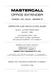
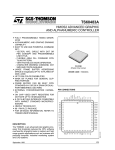
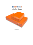
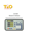
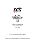
G6S/G3S Configuration Utility User Guide Copyright © 2013 Gosafe Configuration Utility Users Guide Document Title G6S / G3S Configuration Utility User Guide Version 1.1 Date 2014-05-21 Status Release Document Control ID G6S/G3S LEGAL NOTICE Copyright © 2013 Gosafe Systems This document contains proprietary technical information which is the property of Gosafe Systems, copying or distribution of this document or any of its contents thereof, are strictly prohibited without the express written authority of Gosafe Systems. Offenders will be liable for the payment of damages. All rights are reserved in the event of grant of a patent or the registration of a utility model or design. All specification supplied herein are subject to change without notice at any time. INTRODUCTION Gosafe Systems offers this information as a service to its customers, to support applications and engineering efforts that use the products designed by Gosafe Systems. The information provided is based upon requirements specifically provided to Gosafe Systems by the customers and associates. Gosafe Systems has not undertaken any independent search for additional relevant information, including any information that may be in the customer’s possession. Furthermore, system validation of this product designed by Gosafe Systems within a larger electronic system remains the responsibility of the customer or the customer’s system integrator. All specifications supplied herein are subject to change. 2 G6S/G3S Configuration Utility User Guide Table of Contents Configuration Utility Users Guide .............................................................................................................................................. 2 LEGAL NOTICE ............................................................................................................................................................................ 2 INTRODUCTION ......................................................................................................................................................................... 2 1. Materials Needed to Perform the Configuration Utility ........................................................................................................ 4 1.1 Windows Based PC .............................................................................................................................................................. 4 2. System Requirements for PC ................................................................................................................................................. 5 3. Configuring the Communications Port .................................................................................................................................. 5 2. The Program Section ............................................................................................................................................................. 7 3. Tab “Device” .......................................................................................................................................................................... 7 3.1. Sub-Tab “Software” ............................................................................................................................................................ 7 3.2. Sub-Tab “Hardware” ......................................................................................................................................................... 12 3.3. Sub-Tab “Command List Profile” ...................................................................................................................................... 16 4. Tab “Connectivity” ............................................................................................................................................................... 17 4.1. Sub-Tab “General Setting” ................................................................................................................................................ 17 4.2. Sub-Tab “GPRS Server” ..................................................................................................................................................... 20 4.3. Sub-Tab “SMS Server” ...................................................................................................................................................... 22 4.4. Sub-Tab “User SMS” .......................................................................................................................................................... 24 4.5. Sub-Tab “SMS Forwarding” .............................................................................................................................................. 27 5. Tab “Event” .......................................................................................................................................................................... 28 5.1. Sub-Tab “Event Mask” ...................................................................................................................................................... 28 5.2. Sub-Tab “Combination Event” .......................................................................................................................................... 29 5.3. Sub-Tab “Device Reaction” ............................................................................................................................................... 29 6. Tab “I/O Port” ...................................................................................................................................................................... 31 7. Tab “Geo-Fence” .................................................................................................................................................................. 36 7.1. Sub-Tab “General” ............................................................................................................................................................ 36 7.2. Sub-Tab “Draw Geo-Fence” .............................................................................................................................................. 37 7.3. Sub-Tab “Geo-Fence Config” ............................................................................................................................................ 38 8. Tab “Voice” .......................................................................................................................................................................... 38 9. Tab “Exclusive” ..................................................................................................................................................................... 40 10. Tab “Debug & Upgrade” .................................................................................................................................................... 41 10.1. Sub-Tab “Command Line” ............................................................................................................................................... 41 10.2. Sub-Tab “Printed Log Type" ............................................................................................................................................ 41 10.3. Sub-Tab “Firmware Upgrade” ....................................................................................................................................... 43 3 G6S/G3S Configuration Utility User Guide 1. Materials Needed to Perform the Configuration Utility 1.1 Windows Based PC 1.2 USB Configuration Cable (USB) To the computer that runs the Configuration Utility To the front panel of the G6S/G3S device 1.3 G6S/G3S GPS Vehicle Tracking Device 1.4 Configuration Utility Program 4 G6S/G3S Configuration Utility User Guide 2. System Requirements for PC In order for this Configuration Utility, it must be run on the operating systems listed below: Windows 98SE; Windows ME Windows 2000 SP4; Windows XP SP2 and above (32 & 64 bit); Windows Server 2003 (32 & 64 bit); Windows Server 2008 (32 & 64 bit); Windows Vista (32 & 64 bit); Windows 7 (32 & 64 bit); Windows 8 (32 & 64 bit) Supported System Environments: Microsoft .NET Framework 4.0 or higher 3. Configuring the Communications Port Please run and install the Windows USB Driver “VCP_V1.3.1_Setup.exe” before connecting The USB cable, if you are running x64 OS please install “VCP_V1.3.1_Setup_x64.exe” instead. After the driver is properly installed please connect the device with the computer using the USB cable That is accompanied with this Configuration Utility Program. When launching the Configuration Utility Program the following window will be displayed. Please note: if the USB driver has been successfully installed the utility program will launch in “Auto Conn” Mode. The USB com port will automatically be recognized and the Utility will read the IMEI number of the GSM Module inside of the G6S/G3S. Further, if the SIM Card is also installed In the device, it will also be read and displayed at the lower left side of the “device connection” Window as illustrated on page 7. 5 G6S/G3S Configuration Utility User Guide 1) Connection (Left Side of Screen) Access Setting Serial Port: COM Port selection here. Baud Rate: Default Baud Rate is 9600. Device Model: The Device Model will automatically be read and displayed here. Password: Input new password here. Connect: Establish connection between software and device. Disconnect: Disconnect device and will release the occupied serial port. Wireless Device Assistant Reading and Writing Data ID: Bind: OEM Mode: All: Select this to check mark all commands in utility. Auto Conn: Selected by default, uncheck to manually set connection settings for device. Firstly please have “All” checked. Read all: Software will read out global setting of device at a time. Write all: All the changes on each tab will save to device at a time. Import: Import global configuration file from computer. Export: Export global configuration file to computer. Device Information Device Name: Model name of the device that is currently connecting. IMEI/Device ID: IMEI of GSM module. Hardware Version: Device hardware version. Firmware Version: Device firmware version. SIM Card: If SIM card is recognized by device then MCC and MNC is available here. 6 G6S/G3S Configuration Utility User Guide 2. The Program Section The program section is divided into 8 Tabs: 3. Tab “Device” The First Tab is programming the Device 3.1. Sub-Tab “Software” Software: is the first sub tab for programing the G6S/G3S Vehicle Tracking Device. Icon Description Green Check: Indicates the Command has been “Read” Light Bulb: Move your curser over the light bulb to receive description of the command. Check box: Is ahead of each command. Please check the box in front of the command if needing to “Read” or Write” to the device. On each Sub-Tab there are 3 buttons on the bottom of the page, please note they will only “Read or Write” the current tab. All: Select or Unselect all of the commands on current Tab. Read: Read the setting of commands on current Tab. Write: Write changes to device on the current Tab. Command NAM Example: This is an example of the NAM command is to change the device name in the report message to USER (SMS) and the data string to the SERVER. Default name is G6S. You can also change the name of the device if needed. 7 G6S/G3S Configuration Utility User Guide To SERVER: To USER: *GS06,356496042329318,031427090613,, SYS:G6S;V1.00;V1.0.1, GPS:A;7;N23.164358;E113.428515;0;0;45;1.10# G6S V1.00 LTM 2013-06-06 09:41:22 GPS 1.55/0.50/3/4 N23.164302 E113.428456 SPD:0km/h 0 CSQ -52dBm ACIN=12.13V BAT=3.96V #27 Command OPW The default OEM password “0123456789” is for connecting the device with the configuration tool. If user wants to change the OEM password then every time a device connects with the configuration tool it will ask for the password. Which can entered into the password window. Changing the default password will keep the device secure from someone attempting to change device settings without proper authorization. Command TZN and DST These commands are used to adjust the time information. Example: in report message, e.g. To SERVER: To USER: *GS06,356496042329318,031427090613,, SYS:G6S;V1.00;V1.0.1, GPS:A;7;N23.164358;E113.428515;0;0;45;1. 10# G6S V1.00 LTM 2013-06-06 09:41:22 GPS 1.55/0.50/3/4 N23.164302 E113.428456 SPD:0km/h 0 CSQ -52dBm 8 G6S/G3S Configuration Utility User Guide ACIN=12.13V BAT=3.96V #27 Daylight Saving Time: It is the practice of advancing clocks during the lighter months so that evenings have more daylight and mornings have less. Typically clocks are adjusted forward one hour near the start of spring and are adjusted backward in autumn. In the case of the United States where a one-hour shift occurs at 02:00 local time, in spring the clock jumps forward from the last moment of 01:59 standard time to 03:00 DST and that day has 23 hours, whereas in autumn the clock jumps backward from the last moment of 01:59 DST to 01:00 standard time, repeating that hour, and that day has 25 hours. A digital display of local time does not read 02:00 exactly at the shift to summertime, but instead jumps from 01:59:59.9 forward to 03:00:00.0. In the European Union, on the other hand, since the shift occurs at 01:00 UTC, the autumn shift happens an hour later than the spring shift, local time. Command MGE This command works with the odometer counter feature. The device will accumulate distance based on GPS signal and the motion sensor status. (This will also avoid GPS drifting when the vehicle is stopped). This is set to off by default. Selecting Yes will enable this feature. Command SOS Command ETO This command is used when attaching the engine running hour counter feature; the device will accumulate engine hours based on a digital input pulse. Command MGS Enter the initial value of the odometer in meters. The device will accumulate distance in meters based on the initial entered value. The incremental value can be queried at any time thereafter. Command ETS This command will specify which one of two digital inputs for the device as “Engine Starts” signal input, only if the input is triggered will the device start to accumulate data based on a pre-set engine hour, and this command is also for querying current engine hours, similar to the example of command MGS above. 9 G6S/G3S Configuration Utility User Guide Please note: only two inputs are available here IN3 or IN4 user can select any one of these inputs whichever he is going to use as engine sensing wire: IN3: High level IN4: High level Command SPO This command is for setting the trigger condition for an over speed event. Disable: Disable the over speed event detection. Enter the Speed Range: Only current speed entering pre-set speed range to trigger an event. Leave the Speed Range: Only current speed leaving pre-set speed range to trigger an event. Enter or Leave the Speed Range: Current speed leaving or entering pre-set speed range will trigger an event. Command SPS This command is for setting the over speed range. Example: if command SPO set as “Enter the Speed Range”, when vehicle speed reaches or over 30km/h and last for 5 seconds, an over speed event report will be triggered. Command PPS/PPS0 This command will set the GSM module for power saving mode, when “yes” is selected, the device will go into power saving mode according to below setting: Unregister threshold: Device cannot register to GSM network over 5 minutes will go to power saving mode. No data transmission threshold: Device registered to GSM network but has not any data transmit activity over 5 minutes will go to power saving mode. Awaken interval: The device will stay awake for 3 min when every time device awake. Note: GSM module wakes up when interval timer up, or certain event is triggered (precondition is last GPRS connectivity is valid before device enters power saving, otherwise it will not wake up instantly). Command PPS1 10 G6S/G3S Configuration Utility User Guide This command is to set the GPS module for power saving mode, definition is similar to GSM module. GPS un-fixed threshold: Is the value that the GPS module will actively attempt to acquire satellite position before the module will shut down. Awake interval: Is the value that can be set to stay the GPS module awake after every time it is awake. Command PVM This command is used to setup 3 possible work shifts. “Private Hour Periods” Disable: If you disable this feature, the data string to the SERVER will not contain this information. Full manual: Digital input channel must be specified for this mode, if digital input is triggered (Example: a switch button is connected), the device will switch to private hour mode, it will report data string without current GPS/GSM position to a SERVER. Half manual: Digital input channel must be specified for this mode, if digital input is triggered (Example: when a switch button is connected and pressed on), and current time is inside private hour, device will switch to private hour mode, it will report data string without current GPS/GSM position to SERVER, otherwise it reports as usual. Automatically: Regardless of digital input, device will go to private mode only referring private hour period setting, during private hour period device will report data string without GPS/GSM position to SERVER. Private activity monitoring: The device will go to private activity monitoring mode only referring private hour period setting, during private hour period device will force to report data string with GPS/GSM position and device status to SERVER. It is to monitor after hour movement of the equipment (vehicles). According to above “private hour period on working day” setting, private hour will be: Saturday and Sunday: Whole day. Monday to Friday: During 00:00 to 09:00, 12:00 to 13:30, and 17:00 to 23:59. Command POB This command is to toggle digital output when private hour mode is activated, Definition of “mode” please refer command DIM in tab “I/O Port”. Digital output channel: Specify which output port. Interval: Interval between each output the interval time is in Seconds and rage is 0-65535. 11 G6S/G3S Configuration Utility User Guide Command OAS This command will configure a SERVER IP/Addr address that is responsible for firmware sent over the air (OTA) for upgrading a device. By default it is using our GOSAFE SERVER. Command OAP 3.2. Sub-Tab “Hardware” Hardware: is the second sub tab for programing the G6S/G3S Vehicle Tracking Device. Command MOT This command will enable or disable the motion sensor. No: Motion sensor will be disabled, and please note it is going to affect any event related with motion status judgment. Low sensitivity: Motion sensor is enabled and it requires stronger vibration level for motion status judgment. High sensitivity: Motion sensor is enabled and it requires weaker vibration level for motion status judgment. Command STP This command can sets a duration time for motion status judgment, if motion sensor detects current motion status is still (does not match with vibration level that defines as moving), and last it over 30 seconds, device will consider that the vehicle has stopped. Note: Current version of hardware is not using the motion sensor to detect the parking or motion. The hardware is using accelerometer for sensing the parking or motion. Command PTH This command is to set threshold value for power supply event. External power threshold: If external power supply voltage drops to below 8 volts and last for 10 seconds, a power supply event is triggered. 12 G6S/G3S Configuration Utility User Guide Backup battery threshold: If backup battery voltage drops to below 2.5 volts and last for 10 seconds, power supply event is triggered. Note: The value is x 100mV Command BMO This command will turn on or off harsh driving behaviors detection feature. Command BMS This command is to set acceleration magnitude value threshold for harsh behavior, these values must be carefully calibrate according your practice, and otherwise please keep the factory default setting. Command AMO This command will turn On or Off the accident event detection function. Command AMS This command sets the acceleration magnitude value threshold for harsh behavior. These values must be carefully calibrated, otherwise please keep the factory default setting, and device is able to identify front/rear collision in the event report if an accident has occurred. Command BDS This command is to adjust accelerate meter according to practical device installation direction, on the device sticker it has noticed the default installation direction (left) must point to the engine, which means left side of device must point to direction as vehicle heading. If your installation requires other side point to vehicle heading please change the default setting here accordingly. 13 G6S/G3S Configuration Utility User Guide Command AGP This command is to toggle A-GPS feature for GPS module, if enabled it helps GPS to fix faster, and please note this feature requires GPRS connectivity and will consume GPRS data flow. Command ILO This command can enable the vehicle idle status detection feature. Command ILS This command is to set idle status judgment, device will refer “Ignition status & vibration status & GPS speed” to decide vehicle is under idle or not. Stop duration: Threshold to enter idle status, if ignition is ON, motion sensor detects vibration, has not speed and last over 30 seconds, vehicle will be considered as idle. Moving duration: Threshold to quit from idle status, i.e. Vehicle is under idle already, ignition goes to OFF or there is speed, and last over 30 seconds, vehicle will be considered quitting from idle state. Command GPO This command is to toggle GPS and GSM module, please note if “No” is selected, GSM/GPS connectivity will be disabled. Command JAM 14 G6S/G3S Configuration Utility User Guide This command enables GSM module Anti-Jamming detection feature. The mobile phone jammer is an instrument used to prevent a device from receiving signals from base stations, if “Yes” is selected when it happens devices will report GSM jamming event. Command JMP Command TOW This command will enable the internal Tow detection feature. Command EPM This command will set a serial port communication data format. Disable: Device will use its set serial port for communication. Transparent: Device will not do any data format process from/to peripheral device via serial port. GARMIN: Device will communicate with peripheral device based on GARMIN protocol. Command PKI This command is to modify data string on serial port. Carrying device ID information: Device ID field will be added to data string on serial port. Carrying time information: Current time field will be added to data string on serial port. Carrying position information: GPS/GSM information field will be added to data string on serial port. Command EPS This command is to configuration serial port baud rate to communication with peripheral device. 15 G6S/G3S Configuration Utility User Guide 3.3. Sub-Tab “Command List Profile” Command List Profile: is the third sub tab under Device for programing the G6S/G3S Vehicle Tracking Device. Command YCF This command is to ask the device to execute commands from a command list profile that you can create and save to the device. Command YSF This command is to import command list files for the device to execute automatically when certain conditions are satisfied. There are 5 command list profile slots available and by default they are empty, you must create a note pad .txt file with commands and load that file to the device by assigning a profile number to it, and then these profiles will be available for command FRL to call. Command YGF This command will save individually created list profiles from the device to your computer. The file format will be saved as .txt. Command FRL 16 G6S/G3S Configuration Utility User Guide The command is to specify certain conditions for a device to execute a created command list profile. Example: If ACC “ON to OFF” event is selected and triggered, device will execute commands automatically in command list profile number 5. Note: If multiple conditions are selected at the same time, device only if executes command list profile when multiple conditions are satisfied simultaneously. Command SCF This command is to save global setting of device as a configuration profile, there are 3 profile slots available, which mean you can configure device according to different application and switch between them easily. Command RCF This command is to switch between pre-saved configuration profiles. There are 3 profile slots available. 4. Tab “Connectivity” The Second Tab is for programming the “Connectivity” 4.1. Sub-Tab “General Setting” General Setting: is the first sub tab for programing the Connectivity section for G6S/G3S Vehicle Tracking Device. Command DNU This command will set the report interval mode switching condition, it is valid for SMS and GPRS fixed time report. You will notice that for SMS report (command SSP, command USP) and GPRS server report (command SVP) they have 2 report 17 G6S/G3S Configuration Utility User Guide intervals, “static” and “dynamic” mode. Example: Suppose we select ACC OFF and International Roaming. This means that the device will change its upload mode to “dynamic” when anyone of the features are selected. If we select ACC OFF the device will always change its upload mode to that setting based on the setting to be on or off. If the ACC OFF is off it will be sending a slower rate and when ACC OFF is on then the data will be sending at a higher rate. Note: Multiple conditions is supported, and device will change to “dynamic” mode when any one of them is satisfied. Command ADM The G3S/G6S has been designed to adjust the string length based on your own settings. The field has several options for sending different types of data from the device to the SERVER and USER. There are 8 profiles (ADM0 to ADM7) available in the dropdown tab. and can be selected to use which profile is created for any report to the SERVER and USER. 0 (SMS Server) Selecting this profile will send the string data to the SMS Server. 1(GPRS Server) Note: This is the default profile used by the device sending data to the GPRS Server. Profiles 2 thru 7 are also sending data to the GPRS Server. Example: Select the profile you would like to customize for sending preferred data string to the Server. Make selections by check or uncheck the box next to the field of choice for the selected profile and “Write” it to the device. Select another profile and make your choice of data to send to the Server and “Write” the profile to the device. You can now select between profiles you have created and “Write” the one you select to the device. Command SDM0 This command is to further customize main data type “System Data”, selected sub-data type will be carried. Command SDM1 This command is to further customize main data type “GPS Data”, selected sub-data type will be carried. Command SDM2 This command is to further customize main data type “GSM Data”, selected sub-data type will be carried, please note 18 G6S/G3S Configuration Utility User Guide multiple base station info must be selected in continuous number order from first base station info.. Command SDM3 This command will further customize main data type “COT Data”, selected sub-data type will be carried. Command SDM4 This command will further customize main data type “ADC Data”, selected sub-data type will be carried. Command SDM5 This command will further customize main data type “Device Status Data”, selected sub-data type will be carried. Command HBI This command will set a keep connection live short message interval with GPRS SERVER using TCP/IP and UDP. Normally most of the GSM server providers have different settings in there network that can drop the connection for a device that is not connected for a set period of time that is not sending data to the SERVER and will drop the session. Please set this number according to your network provider’s connection preferences. Command HTM This command is used for setting a device self-test “healthy check” message over GPS and SMS to the SERVER. This can check the device GPS, GSM, Heartbeat Sensor, CPU, and other internal components to ensure the device is functioning properly. Command DIS This command will send a report based on certain travel distance and/or certain degree of angle. Example: The device will send a report when every 1KM of distance is travelled, and also report if the vehicle heading has changed over 10 degrees or more based on the input settings. Setting the “Fixed Distance” and “Turning Angle” to 0 will 19 G6S/G3S Configuration Utility User Guide turn off this function. Setting the “Turning Angle” to 20 will send less data to the SERVER and a lower number will send more data. Command EFM This command can record offline data and report its behavior to the SERVER. The device has a 4Mbit flash memory internal storage for offline data when GPRS is offline. Enable offline data buffer: If set to “yes” the device will save data to flash memory when GPRS is offline, and report it to SERVER when GPRS comes back online. Priority: Specify offline data report priority when GPRS comes back online, “offline data prior” means reporting all offline data to the SERVER as soon as possible, while “real time data prior” means reporting offline data when device is idle (between real time report interval). Erase Flash: If “yes” is selected and you click on the “write” button, the flash memory will be formatted. 4.2. Sub-Tab “GPRS Server” GPRS Server: is the second sub tab for programing the Connectivity section for G6S/G3S Vehicle Tracking Device. Command APL This command is to specify SIM card according to your location, device has storage various mobile networks APN information around the world to automatically fulfill APN information once a SIM card is inserted. Edit: It is for you to review all the supported networks for each country and add more based on your requirement. Command APN This command is for you to input your APN information and also a Name and Password here if required for your SERVER provider. You may also set it up for a private 20 G6S/G3S Configuration Utility User Guide Command SVR This command is to setup periodical report to host SERVER, if “disable” is selected device will not report periodically to SERVER. IP/Domain: IP address or Domain name is inputted here TCP port: Specify SERVER TCP port number. UDP port: Specify SERVER UDP port number. Mode: Specify data transfer protocol, “TCP command & UDP data” means only command interaction will use TCP, regular data report will stick with UDP to save on data flow. Enable ACK via UDP: Acknowledgement message will be sent when using UDP protocol. Command SVT This command will set a timeout value to the backup SERVER when using ACK is enabled. Command BSV This command is to setup backup SERVER when main host SERVER is unavailable. Command BDU This command send$ How many records do you want to send in 1 packet. Normally if you want real time tracking you need to select 1. If you want the device to send more data packets to the server increase the value. Command SVP;0 This command will set periodical “static” report to SERVER, device is able to switch between “static” mode and “dynamic” 21 G6S/G3S Configuration Utility User Guide mode according to vehicle status change (Please refer command DNU for supported conditions). Interval: Device will report position interval based on this value. Unit: Report time unit. Report mode: “Disable” means device will not report to SERVER. “GPS prior” means device will prefer to report GPS position when GSM and GPS position information both available. “GPS & LBS” means device will report GSM and GPS position both to SERVER. Data format: “Disable” means device will not generate any data. “HEX” means device will generate data that coded with HEX. “ASCII” means device will generate data that coded with ASCII. Command SVP;1 This command is to set periodical “dynamic” report to SERVER, when the selected conditions in command DNU is satisfied, device will report according this setting, and otherwise it will stick with “static” mode. Interval: Device will report position interval based on this value. Unit: Report time unit. Report mode: “Disable” means device will not report to SERVER. “GPS prior” means device will prefer to report GPS position when GSM and GPS position information both available. “GPS & LBS” means device will report GSM and GPS position both to SERVER. Data format: “Disable” means device will not generate any data. “HEX” means device will generate data that is coded with HEX. “ASCII” means device will generate data that coded with ASCII. 4.3. Sub-Tab “SMS Server” SMS Server: is the third sub tab for programing the Connectivity section for G6S/G3S Vehicle Tracking Device. Command SSN This command is to set phone number that has Administrator authority, please have the country code ahead. 22 G6S/G3S Configuration Utility User Guide Command SSP;0 This command is to set periodical “static” report to Administrator phone number, device is able to switch between “static” mode and “dynamic” mode according to vehicle status change (Please refer command DNU for supported conditions). Interval: Device will report position interval based on this value. Unit: Report time unit. Report mode: “Disable” means device will not report to Administrator phone number. “GPS prior” means device will prefer to report GPS position when GSM and GPS position information both available. “Periodical voice call” means device will proactive to call administrator phone number periodically, and if you pick up the call you can voice monitoring the vehicle (microphone installation is required). Data format: “Disable” means device will not generate any data. “ASCII” means device will generate data that coded with ASCII. Command SSP;1 This command is to set periodical “dynamic” report to Administrator phone number, when the selected conditions in command DNU is satisfied, device will report according this setting, and otherwise it will stick with “static” mode. Interval: Device will report position interval based on this value. Unit: Report time unit. Report mode: “Disable” means device will not report to Administrator phone number. “GPS prior” means device will prefer to report GPS position when GSM and GPS position information both available. “Periodical voice call” means device will proactive to call administrator phone number periodically, and if you pick up the call you can voice monitoring the vehicle (microphone installation is required). Data format: “Disable” means device will not generate any data. “ASCII” means device will generate data that coded with ASCII. Command ACM This command is to customize command accessibility for administrator phone number. Please note that when using this configuration software it is under OEM (OEM>Administrator>User) authority. Selected commands are open for administrator (SMS Server phone number) to use. 23 G6S/G3S Configuration Utility User Guide 4.4. Sub-Tab “User SMS” User SMS: is the fourth sub tab for programing the Connectivity section for G6S/G3S Vehicle Tracking Device. Command PIN This command will set the PIN number for accessibility of the SIM card. Its default is 1234 normally you do not need to specify it. Command SIM This command can query the current SIM Phone Number. Command BLS This command is a feature that can call a USSD number and you will receive back information on account balance for prepaid SIM cards. USSD Command: A protocol used by GSM cellular telephones to communicate with the service provider's computers. Interval: Here you can set this for you to receive a message every 1 Day or every 5 Days. Unit: Here you have 3 selections Day/Week/Month and works in conjunction with the interval setting. Low Balance Threshold: Here you can set the amount of currency to a low balance for notification. Command URL This command is to set Google map hyperlink in the report message to USER phone number. Mode: “GPS” means map API that able to parse according GPS position, and “GSM” means map API that able to parse according GSM position. 24 G6S/G3S Configuration Utility User Guide URL: GPS or GSM location parser hyperlink, e.g.: http://maps.google.com/maps?q=%n,%e&t=m&z=16 Sample of SMS report to USER with map hyperlink: Content of message G6S V1.00 LTM 2013-06-06 14:17:12 http://maps.google.com/maps?q... ETD:6/ACC ON CSQ -52dBm ACIN=12.08V BAT=3.86V #301 Explanation Device name/Firmware version Date/Time Google map hyper link Event ID/User defined event name/Data GSM network signal strength External power voltage Built-in battery voltage Consumed messages Command SCN This command is to set server center number, normally leave it as default or consult your network provider for this information. Command UCM This command is to customize command accessibility for USER phone number. Please note that when using this configuration software it is under OEM (OEM>Administrator>User) authority. Selected commands are open for USER phone number to use. Command UNO0 This command is to set USER0 phone number, please have country code ahead. Command UPW0 This command is to set USER0 command password, default is 1234, it means when you try to send command to device must carrying the right password in command, otherwise device will not accept. Example: 1234, VER to query information of device. 25 G6S/G3S Configuration Utility User Guide Command USP0;0 This command is to set periodical “static” report to USER0 phone number, device is able to switch between “static” mode and “dynamic” mode according to vehicle status change (Please refer command DNU for supported conditions). Interval: Device will report position interval based on this value. Unit: Report time unit. Report mode: “Disable” means device will not report to USER0 phone number. “GPS prior” means device will prefer to report GPS position when GSM and GPS position information both available. “Periodical voice call” means device will proactive to call administrator phone number periodically, and if you pick up the call you can voice monitoring the vehicle (microphone installation is required). Data format: “Disable” means device will not generate any data. “ASCII” means device will generate data that coded with ASCII. “URL” means device will report position by using map hyperlink in message. Command USP0;1 This command is to set periodical “dynamic” report to USER0 phone number, when the selected conditions in command DNU is satisfied, device will report according this setting, and otherwise it will stick with “static” mode. Interval: Device will report position interval based on this value. Unit: Report time unit. Report mode: “Disable” means device will not report to USER0 phone number. “GPS prior” means device will prefer to report GPS position when GSM and GPS position information both available. “Periodical voice call” means device will proactive to call administrator phone number periodically, and if you pick up the call you can voice monitoring the vehicle (microphone installation is required). Data format: “Disable” means device will not generate any data. “ASCII” means device will generate data that coded with ASCII. “URL” means device will report position by using map hyperlink in message. Command UNO1 This command is to set USER1 phone number, please have country code ahead. Command UPW1 26 G6S/G3S Configuration Utility User Guide This command is to set USER1 command password, default is 1234, it means when you try to send command to device must carrying the right password in command, otherwise device will not accept. E.g.: 1234,VER to query version information of device. Command USP1 This command is to set periodical “static” report to USER1 phone number, device is able to switch between “static” mode and “dynamic” mode according to vehicle status change (Please refer command DNU for supported conditions). Interval: Device will report position interval based on this value. Unit: Report time unit. Report mode: “Disable” means device will not report to USER1 phone number. “GPS prior” means device will prefer to report GPS position when GSM and GPS position information both available. “Periodical voice call” means device will proactive to call administrator phone number periodically, and if you pick up the call you can voice monitoring the vehicle (microphone installation is required). Data format: “Disable” means device will not generate any data. “ASCII” means device will generated data that coded with ASCII. “URL” means device will report position by using map hyperlink in message. 4.5. Sub-Tab “SMS Forwarding” SMS Forwarding: is the fifth sub tab for programing the Connectivity section for G6S/G3S Vehicle Tracking Device. Command SMT This command can setup automatic forwarding from a specific number. Up to 3 phone numbers are supported, the device will forward the message that it receives from these 3 phone numbers to User0/User1/Administrator/GPRS Server. 27 G6S/G3S Configuration Utility User Guide 5. Tab “Event” The Third Tab is programming the “Event” 5.1. Sub-Tab “Event Mask” Event Mask: is the first sub tab for programing the G6S/G3S Vehicle Tracking Device. Command ESM This command is to set events for device to detect, it shows all the events (including single event and combination event) that supported with device, selected event means device will monitor and respond according to setting when event happens. Most of events have 2 statuses, Example: TOW event. It means device has 1 status bit flag for TOW, let us suppose for this bit “1”=under TOW, “0”=Normal (Quit TOW), then: Status 0 = if “1” change to “0”, device will report/trigger output for this change. Status 1 = if “0” change to “1”, device will report/trigger output for this change. And so on for the rest of events. By the above setting it means device will report to USER/Administrator/SERVER (GPRS) or trigger output when vehicle is entering TOW status, but will ignore (not report/trigger any) when vehicle leaving TOW status. Event report clear type: “automatically” means after event report, device will automatically reset event report bit flag. “Manually” means the opposite way that you need to send command to reset event report bit flag. Definition of event “Comb1 to Comb8” is defined by Tab “Combination Event”. 28 G6S/G3S Configuration Utility User Guide 5.2. Sub-Tab “Combination Event” Combination Event: is the second sub tab for programing the G6S/G3S Vehicle Tracking Device. Command ERL This command is to define combination event, it is able to bind multiple single events (up to 5 single events and please note that status0 and status1 from identical event cannot be selected simultaneously) as a combination event, and only if all single event flags are active then combination event is active, i.e. It is using “AND gate” logic. Example: By above setting Comb1 will active only if vehicle is over speeding and crossing pre-set GEO-fence. 5.3. Sub-Tab “Device Reaction” Device Reaction: is the third sub tab for programing the G6S/G3S Vehicle Tracking Device. Command EUP 29 G6S/G3S Configuration Utility User Guide This command is to specify output wave shape, and it is corresponding with “Trigger I/O port action” from command EUP above. Digital output channel ID: Specify which output port. Status 0 output mode: Specify wave shape when event is under status 0. Status 1 output mode: Specify wave shape when event is under status 1. After event clearance output mode: Specify wave shape when event report bit flag is reset. Command EUC This command will reset all of the event configuration changes. Command EOB This command is to specify output wave shape, and it is corresponding with “Trigger I/O port action” from command EUP above. Digital output channel ID: Specify which output port. Status 0 output mode: Specify wave shape when event is under status 0. Status 1 output mode: Specify wave shape when event is under status 1. After event clearance output mode: Specify wave shape when event report bit flag is reset. 30 G6S/G3S Configuration Utility User Guide Command ENM This command is to customize event report name to USER. Example: By default Customization G6S V1.00 LTM 2013-02-28 23:51:09 GPS 1.55/0.50/3/4 N23.164302 E113.428456 SPD:0km/h 0 ETD:28/ACC ON CSQ -52dBm ACIN=12.13V BAT=3.96V #28 G6S V1.00 LTM 2013-02-28 23:51:09 GPS 1.55/0.50/3/4 N23.164302 E113.428456 SPD:0km/h 0 ETD:28/Car starts CSQ -52dBm ACIN=12.13V BAT=3.96V #28 6. Tab “I/O Port” The fourth tab is for programming the I/O Port Command AIM This command is to set input port attribution. AD1/IN3: “Analog” means this input is used for voltage value reading (or peripheral device that based on voltage). “Digital” means this input is used for switch detection, and IN3 is defined as low level triggered. AD2/IN4: “Analog” means this input is used for voltage value reading (or peripheral device that based on voltage). “Digital” means this input is used for switch detection, and IN4 is defined as low level triggered. Note: For TTL gate circuit Input>2.4V as high level, input<0.4V as low level. 31 G6S/G3S Configuration Utility User Guide Command DOM This command is to configuration digital output wave shape. Channel ID: Specify which output port. Mode: Rising edge. Duration: 10000ms It means it is going to take 10 seconds to rise from low level to high level, could be like: Mode: Failing edge Duration: 20000ms It means it is going to take 20 seconds to fall from high level to low level, could be like: Mode: Square wave 1 to Square wave 4, they are having same parameter, e.g.: 32 G6S/G3S Configuration Utility User Guide Command DOP This command will set the active speed threshold. Command DIM This command is to set wave shape trigger conditions of digital inputs. Mode: “Level”: It means any input level switching will trigger input (IN) event. “Frequency meter”: “Lower limit” and “upper limit” to specify input frequency range, outside range will trigger input (IN) event. “Pulse meter”: “Initial meter value” means device will accumulate pulse number based on this value. “Meter value threshold” means surpassing this value will trigger input (IN) event. “Low level”: “Duration” means input switching from high level to low level, and keep low level over this duration will trigger input (IN) event. Example: DIM set as above, and let us suppose IN3 is connecting with a high level signal at the beginning. IN3 “status0: high level to low level” event will be triggered if: Signal high level goes to low level and last over 10000ms (10 seconds). “High level”: “Duration” means input switching from low level to high level, and keep high level over this duration will trigger input (IN) event. Example: DIM set as above, and let us suppose IN1 is connecting with a high level signal at the beginning. 33 G6S/G3S Configuration Utility User Guide IN1 “status0: low level to high level” event will be triggered if: Signal high level goes to low level, then low level goes back to high level again and last over 5000ms (5 seconds). “Rising edge”: “Initial meter value” means device will accumulate rising edge number based on this value. “Meter value threshold” means surpassing this value will trigger input (IN) event. “Failing edge”: “Initial meter value” means device will accumulate failing edge number based on this value. “Meter value threshold” means surpassing this value will trigger input (IN) event. “Edge”: “Initial meter value” means device will accumulate rising and failing edge number based on this value. “Meter value threshold” means surpassing this value will trigger input (IN) event. Important Note: IN1 & IN2 is low level triggered (which means when IN1 & IN2 is floating, their default input level is HIGH) IN3 & IN4 is high level triggered (which means when IN3 & IN4 is floating, their default input level is LOW) Command ADS This command is to set Analog-Digital converter sample rate. Sample rate, or sampling frequency defines the number of samples per unit of time (usually seconds) taken from a continuous signal to make a discrete signal, the reciprocal of the sampling frequency is the sampling period or sampling interval, which is the time between samples. Sample Period: 1/frequency. Sample Times: Times of each AD sampling. Command ATH This command is to set analog input voltage event. Channel ID: Specify which input to use, please note set input as AD via command AIM in advance. Lower limit & Upper limit: Specify event triggered voltage range, and inside range is defined as “Normal”. Duration time: Over this duration time will trigger event. Command IBO This command is to set 1-WIRE peripheral device. 34 G6S/G3S Configuration Utility User Guide Disable: 1-WIRE data wire is disabled. iButton: To use driver ID. Temperature sensor: To use temperature sensor. Command IBP This command is to set iButton (driver ID) working mode Enable permit iButton verification: “no” means device will not verify with iButton white list (command IBI), any iButton input is able to start, device will report current GPS/GSM position and iButton ID to server, digital output is disabled. “Yes” means device will compare input iButton ID with permit list, if match vehicle is able to start, digital output is disable. If not match device will report current GPS/GSM position and illegal ID to server, digital output or not depending on Enable digital output. Enable digital output: Specify when illegal iButton input happens to trigger wave shape output. Command TMP This command is to set temperature range event, only valid when command IBO set as “Temperature sensor”. Lower limit & Upper limit: Set temperature range, outside this range will trigger 1-WIRE temperature event report. Duration time: Temperature outside this range over this duration will trigger event. 35 G6S/G3S Configuration Utility User Guide Command IBI This command is to save iButton ID as legal iButton, up to 16 IDs is supported. Command IBC This command is to reset iButton settings to default. 7. Tab “Geo-Fence” The fifth tab is for programming the Geo-Fence 7.1. Sub-Tab “General” General: is the first sub tab for programing the G6S/G3S Vehicle Tracking Device. Command GOF This command is for setting the Geo-fence mask. The device supports up to 156 Geo-fences by default only the first 36 G6S/G3S Configuration Utility User Guide 16 are enabled. Check mark the All box then write to the device will enable all 156 Geo-fences for you to setup and use, or select them individually. Note: The first 28 can use the Polygonal, Rectangular, and Circular Geo-fences. The Next 29 to 156 can only use the Circular Geo-fences and you can set them up more than 100 meters. Command UFM This command is to open Geo-fence for a USER to use, checked box means it is open to USER0 and USER1. 7.2. Sub-Tab “Draw Geo-Fence” Draw Geo-Fence: is the second sub tab for programing the G6S/G3S Vehicle Tracking Device. This command is to draw Geo-fence and set trigger conditions. Draw Type: Specify Geo-fence shape, please note only Geo-fence number1 to number28 support “Round/Rectangle/Polygon”, and while number29 to number 156 supports “Round” only. Type: “Geo-fence In” means this Geo-fence event will be triggered when entering, “Geo-fence Out” means this Geo-fence will be triggered when leaving. “In or Out” means event will be triggered when crossing. 37 G6S/G3S Configuration Utility User Guide 7.3. Sub-Tab “Geo-Fence Config” Geo-Fence Config is the third sub tab Command GFS This command is to set the time range restriction for Geo-fence event detecting on daily basis. Example: For Geo-fence number 1 it only valid during 08:00 to 12:00, 13:00 to 18:00, 1900 to 22:00 on Monday to Friday Command GFS This command is to set speed range restriction for Geo-fence detecting. Type: “Invalid” means this feature disabled. “Inside range” means if vehicle inside speed range Geo-fence number 1 event will be triggered. “Outside range” means if vehicle outside speed range Geo-fence number 1 event will be triggered. Min Speed” & “Max speed: Define speed range. 8. Tab “Voice” VOICE SECTION: 38 G6S/G3S Configuration Utility User Guide Command PWL This command is to modify phone number list that authorized to use voice related features of device, 16 phone numbers is supported, and please note that microphone and speaker installation is needed. Command MWL This command is to specify which phone number from above command PWL to have authorization of voice monitoring, which means when phone number 1 “123456” from PWL calls, device will pick it up and enable microphone of device (Speaker disabled), and you can hear from vehicle. Command HWL This command is to specify which phone number from above command PWL to have authorization of hotline, which means when phone number 2 “1234567” from PWL calls, device will pick it up, and enable microphone & speaker of device for conversation. Command QWL This command is to specify which phone number from above command PWL to have authorization of inquiry position, 39 G6S/G3S Configuration Utility User Guide which means when phone number 3 “12345678” from PWL calls, device will pick not it up, but will reply a message with current position. Command SWL This command is to specify which phone number from above command PWL to have authorization of SOS, which means when Panic button is pressed, device will call phone number 4 “12345678” from PWL automatically. Command VOE This command is to toggle all voice features of device. Enable voice SOS: “Disable” means when panic button is pressed, device will not call the specific SOS phone number. “Communicate” means when panic button is pressed device will enable microphone & speaker, and call SOS phone number. “Monitoring only” means when panic button is pressed device will enable microphone only and call SOS phone number. SOS input channel: Specify which input to connect with panic button, please note if use IN3/IN4, need to set as digital. Command AGN This is for setting up values for microphone gain and speaker gain. 9. Tab “Exclusive” EXCLUSIVE SECTION: *Note: This section is reserved for programming of the G737IC and G79W 40 G6S/G3S Configuration Utility User Guide 10. Tab “Debug & Upgrade” The Eight Tab is for Device Debugging and Firmware Updating 10.1. Sub-Tab “Command Line” Command Line Terminal The command line terminal is used to manually input any command from the G3S/G6S protocol. You can read back current command settings and also you have the ability to make command changes here in the terminal for the device. Example: In the screen above the user typed command VOE in the terminal and after pressing enter the value stored in that register will display on the screen. The command APN here was initially set to APN:sl1.korem2m.com and was changed by inputting preferred changes with the command name first then semicolon to separate the individual changes APN;gosafe;guest;guest. 10.2. Sub-Tab “Printed Log Type" 41 G6S/G3S Configuration Utility User Guide Printed Log Type UGP With this utility you have the ability to read various data strings directly from the connected device and also save it to a log file for later viewing. Printed Log Type (UGP): This mode is to print real time packet in the debug window. NULL: This is zero for no log. GSM (AT+): The GSM module communicates with AT protocol command string. GPS (NMEA): This item reads the GPS NMEA protocol command string. Tracker: This item reads directly from the MCU of the tracker. Read: Write: Click on write to activate selected drop down setting. Exit: Click to exit the debug mode you are currently working with. Save: Click on save to write the data to a log file and save on the computer. 42 G6S/G3S Configuration Utility User Guide 10.3. Sub-Tab “Firmware Upgrade” This command is for firmware local upgrading of your device. Click on “Select File” and direct file browser to the upgrade file, then click on “Upgrade” to start. Once the firmware upgrade has been completed the device will reboot itself to finish the process. 43