1
MCH User Manual Rev 1.8
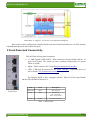
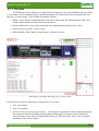
Illustration 4: Tongue 3: PCIe Gen 3 Switch Block Diagram
Each virtual switch configuration is highly flexible and each Virtual Switch has its own PCIe domain
with dedicated upstream and downstream ports.
2 Front Panel and Connectivity
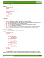
The MCH has 4 Front panel connectors:
•
2 x GbE Uplinks (GbE1,GbE2)– RJ45 connectors directly linked with the 16
ports GbE Switch. The switch provides switching functionality for system
Fabric A(1GbE).
•
Mgmt – RJ45 connector for 10/100 Ethernet management interface.
•
USB – USB mini B connector for the Serial interface . It provides access to
the on board CLI (command line interface)
The Samway-MCH is also equipped with the MicroTCA Hot-swap Handle
and the LEDs defined in MicroTCA .
Illustration 5:
Front Panel
Name
Color
Description
Blue Led
Blue
Hot swap led
Led 1
Red
Status Led:
off – Status ok
Red – error present
Led 2
Green
On – PP is present
Table 1: MCH LEDs
www.samwayelectronic.com
5/38