1
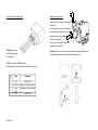
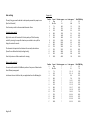
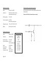
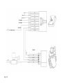
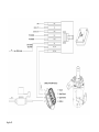
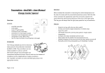
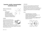
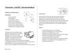
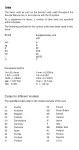
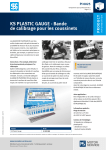
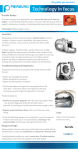
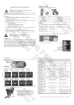
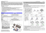
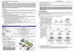
Tecomotive - tinyCWA – User Manual
(manual Version)
Operation
When activated the controller sends the chosen speed signal to the pump
where the internal pump electronics then set it to the right speed.
Features
Overview
Contents
-
tinyCWA controller
Fuse holder
Fuse(s)
Connector 8 pin (controller)
Connector 3-4 pin (water pump)
Set of screws (controller mounting)
Introduction
The Pierburg CWA200 was the first
electronic water pump for line production
introduced by BMW in 2004. They are now
widely available in used cars and the
aftermarket and got many advantages over
conventional mechanical pumps. Some of
which are the freedom of installation and
the independence of engine revolutions. Also the pumps are very well built
and with its brushless canned motor they are practical maintenance free.
The “tinyCWA” controller can control the pump in the appropriate manner.
Page 1 of 9
-
Simple to set up with only one rotary switch
Choose your favorite pump speed in sixteen steps
A seven LED display shows the current pump speed
Compact and robust anodized aluminum case
Additional 10Hz PWM (500mA “nearly” open collector) output
Installation
Connection
Installation drawing scale 1:1
We made the connection as easy and intuitive as possible. So in general
that means that the same color cables are meant to connect to each other.
A detailed connection diagram can be found on the last page.
Even though the CWA200 is electronically regulated to a max. load of 15
amps you should always use the fuse / fuse holder that comes with the kit.
Connector: Controller (8 pin)
Info: If you do not want any standby
functionality you can connect the red
wire (pin 2) to the ignition switch, too.
Attention: The 10Hz PWM output can
only handle a maximum of 0.5 amps!
Changing the screws
To mount the controller on a front panel you can
change the four case screws (M3) to the longer
ones which come with the kit.
Please only change one at the time. There are
little
spacers inside the case which can get out of place
without the screw.
(See the picture at the first page)
Of course the controller can be mounted anyway you like. (E.g. with double
sided tape or zip ties …)
Page 2 of 9
PI
N
1
2
3
4
5
6
7
8
Color
Connection
Black
Red
Yellow
Black
Orange
Blue
Grey / Red
Grey / Black
Ground GND Battery +
Ignition key +
Not needed – please isolate
Not needed – please isolate
10Hz PWM (500mA “nearly” open collector) output
Signal wire water pump
Signal ground wire water pump
Pin2 Red
High
High
Low
Low
Pin3 Yellow
High
Low
High
Low
Controller Function
- working - standby - off - off -
Connector: Water pump (4 pin)
Water pump installation
In and outlet of the pump are shown in
the picture.
To get a decent coolant circulation the
pump should suck the water out of the
bottom radiator port and then pump it
back into the engine.
Also it is recommended to mount the
pump as low as possible.
Attention: The main
current flows through
pin 1 and pin 4.
Attention: Please only mount the pump with appropriate rubber dampers
because high vibration can damage the internal electronics!
(CWA200 15 amps / CWA400 30 amps)
Please only use wires which are able to handle the current!
PI
N
1
2
3
4
Page 3 of 9
Color
Connection
Red
Grey / Red
Grey /
Black
Black
Battery +12V
Signal wire from controller
Ground wire from controller
Ground GND
Basic settings
The only thing you need to decide is what speed you want the pump to run.
(See the list beside)
Turn the rotary switch to the associated character. Done.
Using the rotary switch
Right in the center of the controller’s front panel you’ll find the rotary
switch. By turning it to a specific character you are able to set up all the
things the controller can do.
The character that points to the bottom is the currently selected one.
(You will see a little white dot by looking closely.)
Also it helps to use a little screwdriver for turning.
Rotary switch position’s
You can turn the switch to 16 different positions. Every one of them stands
for a different pump speed.
Just choose the one that’s best for your application from the following list.
Page 4 of 9
Program list
Position
0
1
2
3
4
5
6
7
8
9
A
B
C
D
E
F
Speed Rev/min approx.
Stop
0
Min. Rev.
18
7%
400
14%
700
21%
1000
28%
1325
35%
1640
42%
1950
51%
2320
58%
2630
65%
2950
72%
3250
79%
3570
86%
3880
93%
4190
100%
4500
Position
0
1
2
3
4
5
6
7
8
9
A
B
C
D
E
F
Speed
Stop
Min. Rev.
7%
14%
21%
28%
35%
42%
51%
58%
65%
72%
79%
86%
93%
100%
Rev/min approx.
?
?
?
?
?
?
?
?
?
?
?
?
?
?
?
?
CW A200
CW A50
L/min approx. *
0
0,45
10
18
26
34
42
50
60
68
76
84
92
100
108
116
10Hz PWM Duty
0%
7%
13%
20%
27%
33%
40%
47%
53%
60%
67%
73%
80%
87%
93%
100%
L/min approx.
0
0,1
1,5 – 2
3,5 – 4
5–6
7–8
9 – 10
10 – 12
13 – 15
15 – 17
16 – 19
18 – 22
20 – 24
22 – 26
23 – 28
25 – 30
10Hz PWM Duty
0%
7%
13%
20%
27%
33%
40%
47%
53%
60%
67%
73%
80%
87%
93%
100%
Specifications Controller
PIN 6 - 10Hz “nearly” open collector output circuit
Name:
Tecomotive „tinyCWA“
Dimensions:
51x51x13mm (without connector)
51x51x24mm (with connector)
This is the internal circuit of the controllers 10Hz open collector output.
(for information)
Operating voltage:
8 to 16 Volts
Current consumption: max. 40mA
about 10mA in Standby mode
Temperature range:
-40°C to +100°C (-40°F to +212°F)
Weight:
about 40 grams (1.4 ounces)
Specifications Water pump
Name:
Pierburg „CWA200“
Dimensions:
100x125x175mm
Operating voltage:
8 to 16 Volts
Current consumption: max. 15A
0,2mA in Standby mode
Speed:
Pump pressure:
Volume flow:
Temperature range:
Page 5 of 9
18 to 4500rpm
0.45 bar
116 l/min
-40°C to +140°C
-40°F to +284°F
Example part numbers:
Pierburg:
7.00294.17.0
BMW:
11 51 7 586 925
BMW old:
11 51 7 563 183
11 51 7 546 994
11 51 7 521 584
11 51 7 545 201
Please use this PIN only if you know what you are doing!
Safety notes
Don’t lay cables or connectors in areas which are exposed to spray water.
Disclaimer
Don’t mount the wires / sensor in areas which are exposed to moving or
rotating parts.
The installation should only be done by experienced or special trained
personnel with the necessary knowledge.
We cannot be held liable for any damages on your car, engine or the
product itself!
General notes
Before you plug in the devices make sure all the cables are wired correctly!
The installation needs special automotive and electrical knowledge.
Improper connection and use can damage your car, the engine or the
product itself.
Installation
Before you start with the installation disconnect the cars battery to prevent
any unintentional short circuits.
Pay attention to any potential safety notes from your car manufacturer.
(E.g. regarding airbags, alarm systems, ECU’s or immobilizers)
Avoid smoking, fire, flying sparks or static electricity charges.
Be careful not to damage any parts (e.g. battery, wires, hoses…) while
drilling holes.
Page 6 of 9
Operation
Any modifications on your car could be against the law.
It is your responsibility to get all the necessary information and permissions
to drive the car legally.
If you drive your car without proper legality and permissions you could lose
your insurance coverage and could be committing a criminal offence.
Current consumption over longer periods of time
The devices are consuming a little bit of current even in standby mode.
If you don’t use them over a longer period of time it is recommended to
disconnect them entirely to not damage the cars battery.
Application
The device described in this manual is only tested with the water pump
“CWA200” made by the “Pierburg Pump Technology GmbH” which is
available at the replacement department of the “BMW AG”.
A functional guarantee can only be given by using this product.
Page 7 of 9
Page 8 of 9
Page 9 of 9