Transcript
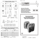
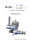
I
子 ZH
司
电 JI
公
H
致
C
积 I
限
A
E
海 GH
T
有
I
上 AN
子
SH
ZH
电 JI
致
积 AI
海 GH
上 AN
Manual for WR57x series of Electric ControlPreface V1.0
1.2 Outside View of WR57xSeries
The appearance of WR57x series is as shown in the figure below
Note:Please
read this User Manual and the Instruction Guide for sewing
equipment in detail before use and for correct use the equipment shall be installed
and operated by persons with vocational training.
grounding must be correctly made when installing the
controller, otherwise, the controller will fail to operate normally, or in more
serious case, be shocked by electricity.
1. Product Introduction
1.1 Overview
For the WR57x series AC servo system for industrial sewing machine, its motor is directly coupled to the upper
spindle of the machine and the motor is directly driven with the controller, offering a more flexible and convenient
control performance, and further more, the motor and controller can be matched as required so as to meet the
requirement of various sewing machines in terms of power and speed. A modular design is adopted for the system and its
functions can be expanded only by adding a needle stopping magnet with which auto stop can be realized. It has the
features of easy installation, convenient adjustment, compactness . large moment, low noise, high efficiency and more
electricity saving. The control strategy of the optimized AC servo motor will allow for a high control precision of
rotation speed and quick needle stop speed. The direct drive installation mode facilitates a more simple installation and
minimize the overall vibration and allows for a more stable system running.
司
公 H
限 EC
T
SH
Note:Proper
1.3 Basic Parameters
Type of controller
WR57x series
Type of motor
DC brushless servo motor
Rated voltage
AC 220V ± 20%
Rated power
500W~~550W
Highest rotating speed:
3500rpm~~8000rpm
Maximum output torque
3.0Nm~~3.6Nm
2 Installation
Installation steps
Step 1:Installation of the controller. It is required to drill holes in size as shown in the figure below and put in mounting
screws of controller if no location holes are pre-drilled on the se wing machine table.
有
This product is only applicable to the sewing equipment of the specified range and is not intended for other applications.
Our company has the final authority for the interpretation of this User Manual.
For any queries on our product and any opinions or suggestions on our service, please do not hesitate to contact us at any
time.
Safety instructions:
1、 Please read this Manual carefully and conscientiously before installation and debugging.
in this Manual are for special care and shall be strictly observed so as
2、 Safety points marked with the symbol
not to cause any unnecessary damage.
3、 This product shall be installed and operated by persons with vocational training.
4、 Ensure that the housing case is securely earthed and conforms to voltage range and technical requirements as
shown on the product nameplate.
5、 Disconnect the system power supply when performing the following operations:
a)
When installing the machine;
b)
When plugging and unplugging any connector in control box;
c)
When threading, changing a needle and raising the nose;
d)
When the machine is not in use and under repair or adjustment;
e)
When While procedure upgrading
6、 Screw down all fasteners so as to prevent occurrence of vibration or needle position deviation abnormities in time
of sewing.
7、 Wait for above 10 seconds every time when restarting the control system after turnoff.
8、 Setting of the system control parameters or maintenance and repair shall be done by professional personnel
having received related training.
9、 Make sure that all parts and fittings used for maintenance must be the ones supplied or approved by our company
for use.
Note: while fastening the screw,
it is prohibited to knock it directly
so as to avoid that the electric
control cabinet and the plug-in
motor fall after long-term vibration.
Step 2:Installation of motor. Install the motor to the upper spindle of the machine and make it tight
※ Step 3: Installation of belt pulley as shown in the figure below.
1. Rotate the belt
cap till both sides of
the belt have an
equal distance to the
arrow position.
The two scale
lines shall aim
at the center of
the
mounting
bolt.
2. Screw down the
three screws
3. Operation Guide
3.1 Connection of each interface of the controller
Motor power cord
Fuse
Pedal wire
Motor encoder cable
Safety switch wire
Program write port
sewing machine lamp connector
-1-
-2-
3.2 Dial Operation Box
There is one 4-digit dial switch on the operation box which is used for setting of the motor rotation speed and it is
described as follows:
3.2.1 Description of 4-digit dial switch
Sliding ON up
stands for 1
Failure display
Sliding ON down
stands for 0
1)I speed control :The operation box is divided into 15 scales, and each 250rpm is 1 scale:
0000:500 rpm
0101:1750rpm
1010:3000rpm
0001:750 rpm
0110:2000rpm
1011:3250rpm
0010:1000rpm
0111:2250rpm
1100:3500rpm
0011:1250rpm
1000:2500rpm
1101:3750rpm
0100:1500rpm
1001:2750rpm
1110:4000rpm
司
公 H
限 EC
有 IT
子 ZH
电 JI
致
积 AI
海 GH
上 AN
For example:
SH
0000 stands for 500rpm
0001 stands for 750rpm
0010 stands for 1000rpm
0011 stands for 1250rpm
2)II speed control :The operation box is divided into 15 scales, and each 500rpm is 1 scale:
0000:1000 rpm
0101:3500rpm
1010:6000rpm
4. Description of Failure Modes and Check
The LED red light is constant on when there is no failure. Failure is displayed by way of a blinking red LED light and
only the red LED light is twinkling. The times n for continuous ephemeral twinkling of the red LED light will be the
failure code E n .After one time of slow flashing of the red LED light, the times n for continuous ephemeral twinkling of
the red LED light will be the failure code E(10+n)
0001:1500 rpm
0110:4000rpm
1011:6500rpm
0010:2000rpm
0111:4500rpm
1100:7000rpm
0011:2500rpm
1000:5000rpm
1101:7500rpm
0100:3000rpm
1001:5500rpm
1110:8000rpm
Note:The system will automatically limit the max. sewing speed in accordance with the machine model settings.
3.2.2 Description of speed setting with dial operation box:
Pedal
connector
The connector of the dial operation box and the pedal share
one interface, when reset of speed is required, unplug the pedal
connector after shutoff and compete disconnection of power.
Then connector in the dial operation box, turn on and the casing
led lamp flashes twice slowly (it means finish of setting), then
re-plug in the pedal connector for normal use after
complete disconnection of power.
-3-
Quick twinkling once
stands for E1
Quick twinkling twice
stands for E2
Quick twinkling 3 times
stands for E3
Quick twinkling 4 times
stands for E4
Quick twinkling 6 times
stands for E6
Quick twinkling 7 times
stands for E7
Quick twinkling 8 times
stands for E8
Quick twinkling 9 times
stands for E9
Slow twinkling once and
quick twinkling once
stand for E11
Slow twinkling once and
quick twinkling 3 times
stand for E13
Slow twinkling once and
quick twinkling 4 times
stand for E14
Slow twinkling once and
quick twinkling 5 times
stand for E15
Slow twinkling once and
quick twinkling 6 times
stand for E16
Slow twinkling twice
stands for(E20)
Failure
Remedies
Over-current of hardware
Check if it is well earthed
Over-current of software
Check if it is well earthed
Shutdown or overvoltage in operation
Check the mains voltage.
Shutdown or under-voltage in operation
Check the mains voltage.
Needle stop signal failure
Motor HALL Signal failure
Locked rotor failure of motor
Over-speed failure (wrong indication
of the exceeding max. speed forthe set model)
Check if the needle connector is loose
Check the motor connector for
poor connection.
Check if the motor wire is well
connected, and if it is overloaded
Check if the motor wire connection
is correct
Reserved by manufacturer
Handled by manufacturer
EEPROM initialization error
Handled by manufacturer
EEPROM read and write error
Handled by manufacturer
Pedal zero point exceeds the range
when checked
Pedal zero point exceeds the setting
range
Failure of pedal connected
The failure will alarm on a connected
pedal when in an automatic testing mode
Write success of program
Unplug the operation box after shut
down and power disconnection
The operation manual can be upgraded and issued online
timely ,pay close attention to the website:
-4-
www.jizhitech.com