1
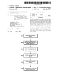
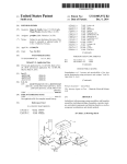
US007907901B1
(12) United States Patent
(10) Patent N0.:
(45) Date of Patent:
Kahn et al.
(54)
METHOD AND APPARATUS TO ENABLE
Mayrhofer, R., Gellersen, H., “Shake Well Before Use: Authentica
tion Based on Accelerometer Data”, In: Proc. Pervasive 2007,
(75) Inventors: Philippe Kahn, Aptos, CA (US);
Springer-Verlag, May 2007, pp. 144-161.
Mayrhofer, R., Gellersen, H., “Shake Well Before Use: two imple
mentations for implicit context authentication”, Adjunct Proc.
Ubicomp 2007, Sep. 2007, pp. 72-75.
Arthur Kinsolving, Santa Cruz, CA
(US); David Vogel, Santa Cruz, CA (US)
(73) Assignee: DP Technologies, Inc., Scotts Valley, CA
Simonite, Tom, “synchronised shaking connects gadgets securely”,
(Us)
Notice:
Mar. 15, 2011
OTHER PUBLICATIONS
PAIRING OF DEVICES
(*)
US 7,907,901 B1
NeWScientist.com news service, http://WWW.neWscientist.com/ar
ticle/dnl29l2, Nov. 13, 2007, 2 pages.
Subject to any disclaimer, the term of this
patent is extended or adjusted under 35
* cited by examiner
U.S.C. 154(b) by 755 days.
(21) App1.No.: 11/855,133
Primary Examiner * Eugene Yun
(22) Filed:
Zafman, LLP; Judith A. SZepesi
(51)
(52)
(58)
(74) Attorney, Agent, orFirm * Blakely, Sokoloff, Taylor &
Sep. 13, 2007
Int. Cl.
H04B 7/00
H04B 5/00
(57)
(2006.01)
(2006.01)
A method and apparatus to provide easier pairing based on
motion data is described. The method of pairing tWo devices
U.S. Cl. ..................... .. 455/41.2; 455/41.1; 455/502
Field of Classi?cation Search ............... .. 455/41.2,
comprises receiving a signal to enter into pairing mode, and
455/41.3, 41.1, 425, 502, 13.2
See application ?le for complete search history.
(56)
ABSTRACT
detecting a motion indicating a pairing. The method further
comprises establishing a secure connection With another
device forpairing, the secure connection establishedbased on
References Cited
the motion, and exchanging data for pairing.
U.S. PATENT DOCUMENTS
2007/0213045 A1 *
9/2007
11 Claims, 7 Drawing Sheets
Hermansson et al. ...... .. 455/425
Fourth Device
140
1
7
'
First Device
110
Motion
Sensor
11s
1
Second Device
120
Motion
7
Sensor
125
Third Device
130
Motion
Sensor
135
Sewer
150
US. Patent
Mar. 15, 2011
Sheet 1 0f 7
US 7,907,901 B1
Fourth Device
140
First Device
1 10
Motion
7
Second Device
120
Motion
Sensor
125
Server
150
y
Third Device
130
Motion
Sensor
135
Fig. 1
l
Sensor
1 15
US. Patent
Mar. 15, 2011
US 7,907,901 B1
Sheet 2 0f 7
Pairing Logic
210
Motion
Sensor
1 15
User Interface
220
Motion Database
235
Motion Identifier
230
Discovery Logic
280
i
Target Device
Identi?cation Logic
240
Device Patterns
245
i
Secure Connection
Key Generation
Logic
Logic
250
255
1
Data Exchange
Logic
260
Pair Data
270
Connection Logic
280
Fig. 2
US. Patent
Mar. 15, 2011
Sheet 3 017
/
Start
\
K
310
)
Initiate pairing
320
i
Detect motions for
pairing
330
i
Establish secure
connection
340
i
Exchange data for
pairing
350
Q End
360
Fig. 3
/'
US 7,907,901 B1
US. Patent
Mar. 15, 2011
Sheet 4 017
US 7,907,901 B1
Start
41 0
Recelve command to
place device in
pairing mode
420
Identify motions
initiating pairing
430
1
Generate key to
create secure
connection
440
1
Device attempts
connection with
identified pair
445
can
established?
450
Inform user of failed
connection attempt
460
Yes
Exchange data for
pairing & close
connection
470
1
End
480
Fig. 4
US. Patent
Mar. 15,2011
Sheet 5 017
US 7,907,901 B1
Start
510
Detect motions
initiating pairing
520
Send out discovery
message
530
No
\
\
Any
response?
540
Time
N0
\
out?
545
Yes I
\/
YesT
Compare motions
detected
555
/Do motions match?\ No
\\
560
/—
\\
Create secure
connection
570
i
Exchange data for
Pairing & close
connection
58°
Fig. 5
US. Patent
Mar. 15, 2011
Sheet 6 017
US 7,907,901 B1
Detect series of
motions
620
i
Identify device
indicated by motions
630
i
Send out connection
request to identified
device
640
7
Create key for
secure channel
based on motions
650
Connection
made?
660
Secure connection
using key
680
L
End
690
Fig. 6
US. Patent
Mar. 15,2011
77
o
Display
Sheet 7 017
US 7,907,901 B1
765
A
700
<—>
710
Processing
775
Unit
750
Mem°ry
A|phanum_eric
Input Devlce
v
780
715
Bus
k
Cursor Control <—>
725
790
Commun_ications
Devlce
Fig. 7
'
720
S322‘;
Non-volatile
Device
storage
>
US 7,907,901 B1
1
2
METHOD AND APPARATUS TO ENABLE
PAIRING OF DEVICES
FIG. 3 is an overview ?owchart of one embodiment of
pairing.
FIG. 4 is a ?owchart of one embodiment of pairing.
FIG. 5 is a ?owchart of one embodiment of associating the
two devices.
FIG. 6 is a ?owchart of an alternative embodiment of
FIELD OF THE INVENTION
The present invention relates to pairing, and more particu
larly to pairing at least two mobile devices to each other.
associating the two devices.
FIG. 7 is a block diagram of one embodiment of a computer
system which may be used with the present invention.
BACKGROUND
DETAILED DESCRIPTION
Pairing describes associating devices with each other. For
example, a multi-device remote control may need to be paired
with the associated television, or a Bluetooth headset may be
paired with the mobile phone that the user would like to use
The method and apparatus described is for enabling pairing
of two or more devices. The process, in one embodiment,
includes putting both devices in pairing mode, then perform
with it.
Generally, in the prior art pairing the devices was a long
and involved process. For example, a typical pairing of a
Bluetooth headset with a phone may include the following
ing a motion such as shaking the devices holding them in the
The headset:
same hand. The movement pattern, in one embodiment, is
used both to identify which devices one intends to pair and
then generate the key that will create the secure connection. In
an alternate embodiment, a certain motion automatically
launches the pairing process. The process then looks for
Put the headset into “Discoverable” mode (usually by hold
nearby devices and attempts to pair with them, only complet
ing a button or sequence of buttons) so that the phone can
?nd it.
Refer to your headset’s user manual to ?nd out the PIN
code.
ing the pairing if the exact motion pattern of that device’s
motion and the date/time stamp of the motion also match. In
steps:
20
25
The phone:
by the accelerometer in each device are of the same magni
tude. In contrast, if the devices were simply held separately,
From the home screen, press and hold the Home key.
Select the “Communications Manager” (second option)
Press the “Settings” menu and choose “Bluetooth Settings”
Choose Menu>Devices
Choose Menu>New
After a few seconds, the name of your headset will be
30
and similar motions were made, there would be a differential
35
not only because humans cannot reproduce the identical
motions, but also because of mass differentials between the
devices.
FIG. 1 is a network diagram of the devices. A ?rst device
110 is designed to be paired with a second device 120. Both
40
devices, in one embodiment, include a motion sensor 115,
125. The user then performs a preset motion with both devices
in one hand. This ensures that both devices receive exactly the
same motion data. This motion data is used to pair the two
devices. This process is described in more detail below.
displayed along with any other Bluetooth devices in
range. Highlight the name of the headset that you wish to
pair and press the ‘Next’ key.
Enter the PIN code (found in the headset manual) to bond
the two devices together.
Press “Next” to pass by the renaming of the headset.
On the services screen, ensure that the “Wireless Stereo”
An alternative pairing may be between the ?rst device 110
and the third device 130. The third device 130, in one embodi
ment, also includes a motion sensor 135. However, in this
service is ticked then press “Done”
Press “Done” on the next screen, then “Done” on the Next,
then “Done” on the next.
Press Exit to leave the Communication Manager
As can be seen, this process is rather involved and requires
a lot of steps, including looking up codes in a handbook and
one embodiment, this happens in the background transpar
ently to the user. By holding the two devices together, they
become effectively one body, and the accelerations measured
example, the third device 130 does not have the processing
45
capability necessary to provide motion analysis, provide
device identi?cation, and/or provide an encryption key for a
secure connection. Therefore, the third device 130 relies on a
server 150 to provide at least some processing and/or memory
working through multiple menus.
SUMMARY OF THE INVENTION
50
A method and apparatus to provide easier pairing based on
motion data is described. The method of pairing two devices
for the connection. In one embodiment, both the ?rst device
110 and third device 130 are coupled to the server 150. In
another embodiment, only one of the devices is coupled to the
server 150, and the other device need not be aware of the
comprises receiving a signal to enter into pairing mode, and
server connection. When a server is involved in the process,
detecting a motion indicating a pairing. The method further
comprises establishing a secure connection with another
any portion of the processing may take place on the server.
An alternative pairing may be between the ?rst device 110
55
and a fourth device 140, which does not have a motion sensor.
The fourth device 140 may be a conventional device which
device for pairing, the secure connection established based on
the motion, and exchanging data for pairing.
does not include an accelerometer or similar motion sensor.
BRIEF DESCRIPTION OF THE DRAWINGS
60
phone including an accelerometer. The pairing of these
devices may be accomplished using the accelerometer to
reduce the complexity and navigation requirements, as will
The present invention is illustrated by way of example, and
not by way of limitation, in the ?gures of the accompanying
drawings and in which like reference numerals refer to similar
elements and in which:
FIG. 1 is a network diagram of the devices.
FIG. 2 is a block diagram of one embodiment of the pairing
mechanism.
For example, the fourth device 140 may be a conventional
Bluetooth headset, while the ?rst device 110 is a mobile
65
be described below.
FIG. 2 is a block diagram of one embodiment of the pairing
logic. In one embodiment, the pairing logic resides on one of
the mobile devices. In one embodiment, only one of the
US 7,907,901 B1
3
4
devices has the pairing logic. In one embodiment, the pairing
At block 340, a secure connection is established. The
secure connection is established based on the motions
detected. In one embodiment, the secure connection is an
logic 210 may be split betWeen the handheld device and a
remote device, such as a server. In another embodiment, both
devices have a pairing logic. In one embodiment, one or both
encrypted connection.
At block 350, data is exchanged betWeen the devices for
of the devices may include a subset of the pairing logic
elements described.
The motion sensor 115 provides data to motion identi?er
pairing. Once devices are paired, their connection can be
automatically established in the future.
230. Motion identi?er 230 identi?es the motion. In one
embodiment, the motion identi?er uses a database of motions
The process ends at block 360.
FIG. 4 is a ?owchart of one embodiment of pairing. The
process starts at block 410. At block 420, a command to place
235 to identify the meaning of each motion. In one embodi
ment, the motions may initiate pairing. In one embodiment,
the user may initiate pairing through user interface 220. User
interface 220 may also be used to de?ne the motions used for
the device into pairing mode is received. In one embodiment,
this command may be initiated through a menu selection,
through a motion, or through other means. In one embodi
pairing. In another embodiment, the motions, stored in
ment, When the device is placed in pairing mode, the system
motion database 235, are pre-de?ned.
In one embodiment, When the motion for pairing is identi
?ed by motion identi?er 230, or initiated by user interface
220, the subsequent motions are passed to target device iden
ti?cation logic 240. In one embodiment, the motion identi?er
230 identi?es the motion components, and passes these iden
ti?ed motion components to target device identi?cation logic
240. For example, a motion component may be a “rapid
indicates to the user to take both devices, hold them together,
and perform a pairing motion. In one embodiment, the device
may provide a list of potential pairing motions, based on the
horizontal shake” or a “clockWise circle,” etc. The target
device identi?cation logic 240 uses these motion compo
20
With a Bluetooth headset. For another example, a double
shake up and doWn may indicate pairing With a particular
25
Secure connection logic 250 then establishes a secure con
30
1000 integer counts. During the initial steady state, in one
embodiment the dominant vector affected by Earth’s gravi
to establish the secure connection. Since the tWo devices are
moved together, they have performed the identical motions,
35
fore, the motion data can be used to ensure that the correct
devices are paired. In one embodiment, relative motion data is
used, instead of absolute motion data. This ensures that even
if there are calibration differences betWeen the accelerom
eters in the tWo devices, the same key is generated.
In one embodiment, the accelerometer data is smoothed,
ms. In one embodiment, each of the axes Will be scaled to
have a normaliZed motion of l-G acceleration equivalent to
generate a key, by key generation logic 255. This key is used
and thus captured substantially identical motion data. There
sensor. In one embodiment, motion data is ?ltered on all three
axes using a loW-pass ?lter. In one embodiment, the loW pass
?lter is con?gured to have a frequency cutoff at 4 HZ. The
?lter removes transient noise and alloWs the detection of hand
movement that exhibits a change of direction greater than 250
nents, and data from the device patterns library 245, to iden
tify Which devices should be paired.
nection betWeen the device and the identi?ed target device. In
one embodiment, the motions (i.e. accelerations) are used to
identity of the devices to be paired.
At block 43 0, the motions initiating pairing are received. In
one embodiment, the motions identify the device to be paired.
For example, a triple shake of the device may indicate pairing
tational ?eld Will be used to determine the accelerometer
orientation on both devices. In one embodiment, this process
is performed for both devices.
At block 440, a key is generated to create a secure connec
40
tion. In one embodiment, the key is generated based on the
exact motions performed by the user, to initiate pairing. In one
embodiment, the key is based on differential motion (i.e. the
relationship betWeen various measurements, rather than exact
?ltered, and/or normaliZed prior to performing the key gen
measurements). This ensures that even if the tWo devices have
eration. This ensures that the tWo devices’ data match if they
experienced the same motions. In one embodiment, a clock
differential betWeen the tWo devices is identi?ed, so that an
“absolute” clock time may be used for comparison purposes.
For example, the system may calculate that one of the devices
is 3 seconds ahead of the other device, and is 0.02 seconds
faster (per second skeW). This may be used to ensure that
When motions are compared, the calculated “absolute” time
When they occur is identical on both devices.
not been cross-calibrated, the proper key is generated. In one
embodiment, the measurement of the accelerometer orienta
45
tion is used to perform an axis translation on both devices.
50
Along With the axis normalization and axis translation, the
directional acceleration and amplitude measurements Will be
equivalent on both devices. In one embodiment, using direc
tion, acceleration amplitude and time, a coded numeric
sequence Will be computed and used as the key for both
Data exchange logic 260 exchanges data for pairing With
the paired device. This data is obtained from Pair data 270,
and any relevant data to be used for future connections is
stored. In one embodiment, the future connection data is also
55
stored in pair data 270.
In subsequent uses of the device, connection logic 280
utiliZes the stored data from pair data 270, to establish a
connection With the other device. In one embodiment, this
occurs automatically When the device is subsequently turned
on. The use of paired devices is knoWn in the art.
nection attempt.
60
FIG. 3 is an overvieW ?owchart of one embodiment of
pairing. The pairing is initiated, at block 320. As noted above,
the pairing may be initialiZed by a user action.
At block 330, the pairing motions are detected. In one
embodiment, if the pairing is initiated by motion, blocks 320
and 330 may refer to the same motions.
devices.
At block 445, the device attempts to connect With the
identi?ed device to be paired. In one embodiment, both
devices attempt to establish a connection. In another embodi
ment, one device is the “host” device Which has the softWare
to establish such a connection, While the other device is the
“client” device Which is more passive, and receives the con
At block 450, the process determines Whether a secure
connection can be established. If not, at block 460, the user is
informed of the failed connection attempt. In one embodi
ment, the connection attempts are retried for a number of
tries, or a preset amount of time, before this occurs. The
process then ends, at block 480.
65
If a secure connection can be established, at block 470, data
for pairing is exchanged. The secure connection is then
closed, in one embodiment. In another embodiment, a pairing
US 7,907,901 B1
5
6
channel is opened, based on the pairing data, so that the
devices are immediately paired for use. The process then
ends, at block 480.
i.e. Bluetooth headset. In another embodiment, the protocol
used by the device is identi?ed, i.e. Bluetooth device. In
another embodiment, the device manufacturer and type is
identi?ed, i.e. Jabra Bluetooth headset. In yet another
embodiment, the precise device is identi?ed, i.e. the Jabra
FIG. 5 is a ?owchart of one embodiment of associating the
two devices. The process starts at block 510.
At block 520, pairing motions are detected. In one embodi
Freespeak headset.
ment, the user may initiate pairing mode prior to performing
At block 640, a connection request is sent out to the iden
ti?ed device. In one embodiment, the request is as targeted as
pairing motions. In another embodiment, the pairing motions
may automatically initiate pairing mode.
possible.
At block 530, a discovery message is sent out. The discov
ery message, in one embodiment, is sent out in the format
indicated by the pairing motions. For example, for a Blue
tooth device, the discovery protocol may be to send out a
“wake-up” message paired with a “trigger connection mes
sage.” Each protocol and/or device may have a different dis
At block 650, a secure channel is created. In one embodi
ment, the secure channel is created by creating a unique key
5
covery message.
At block 540, the process determines whether there was
any response. If not, the process continues to block 545. At
generating the key may be used.
block 545, the process determines whether the pairing has
timed out. If not, the process returns to block 530, to send out
a new discovery message. In one embodiment, the pairing
process is maintained for a preset period of time, or a preset
based on the motions performed by the user. The motion data
may be converted into a series of numbers, i.e. each motion
segment represented by a number. In one embodiment, a
look-up table may be used for this conversion. In one embodi
ment, the series of numbers may be used to generate the key,
through a one way hash function. Alternative methods of
20
At block 660, the process determines whether a successful
connection was made. If not, the process determines if the
attempt has timed out. If not, the process continues to try for
a connection. Otherwise, the process ends at block 690.
number of discovery messages. For example, the system may
If a connection is made, it is secured using the key, at block
attempt pairing for 1 minute, with discovery messages being
680. The data exchange as described above occurs at that
re-sent every 10 seconds. If the system times out, the process
ends at block 550.
If a response is received, at block 540, the process contin
25
point. The process then ends.
30
be used with the present invention. It will be apparent to those
of ordinary skill in the art, however that other alternative
systems of various system architectures may also be used.
The data processing system illustrated in FIG. 7 includes a
FIG. 7 is one embodiment of a computer system that may
ues to block 555.
At block 555, the process compares the detected motions to
establish whether the devices were moved together for pair
ing. In one embodiment, comparing the detected motions is a
three step process.
First, in one embodiment, the systems perform a clock
differential correction. In one embodiment, the clock differ
ential correction involves using the time stamps on handshake
bus or other internal communication means 715 for commu
nicating information, and a processor 710 coupled to the bus
715 for processing information. The system further com
prises a random access memory (RAM) or other volatile
35
messages, to determine clock differential between the
devices. The clock differential may include a per/minute dif
processor 710. Main memory 750 also may be used for stor
ing temporary variables or other intermediate information
ferential as well as a base differential. For example, clockA
may be 3 seconds ahead, while clock B loses 0.1 second per
minute. Once the clock differential is determined, the system
during execution of instructions by processor 710. The sys
40
tem also comprises a read only memory (ROM) and/ or static
storage device 720 coupled to bus 715 for storing static infor
mation and instructions for processor 710, and a data storage
device 725 such as a magnetic disk or optical disk and its
45
to bus 715 for storing information and instructions.
The system may further be coupled to a display device 770,
such as a cathode ray tube (CRT) or a liquid crystal display
has an absolute time available to use for the comparison.
Second, the system in one embodiment accounts for dif
ferent relative positions between the objects being paired.
Since the user can hold the devices together in any con?gu
ration, the detected motions would be along different axes
depending on relative positions. This also compensates for
different accelerometer locations and orientations within the
devices. In one embodiment, a ?rst motion pattern is used to
orient the relative accelerometers. In one embodiment, for
each motion pattern, the ?rst motion is a spike or other notice
storage device 750 (referred to as memory), coupled to bus
715 for storing information and instructions to be executed by
corresponding disk drive. Data storage device 725 is coupled
(LCD) coupled to bus 715 through bus 765 for displaying
information to a computer user. An alphanumeric input
able motion pattern.
device 775, including alphanumeric and other keys, may also
be coupled to bus 715 through bus 765 for communicating
Third, the system compares motions or accelerations at
absolute times. In one embodiment, the motion data is ?ltered
information and command selections to processor 710. An
additional user input device is cursor control device 780, such
50
and smoothed, prior to comparison.
At block 560, the process determines whether the motions
match. If they do not match, the process returns to block 545,
as a mouse, a trackball, stylus, or cursor direction keys
55
to determine whether the process should time out or resend
the discovery message.
If the motions match, at block 570 the secure connection is
created, and data is exchanged for the pairing, at block 580.
60
FIG. 6 is a ?owchart of an alternative embodiment of
commercially available networking peripheral devices such
associating the two devices. The process starts at block 610.
At block 620, a series of motions is detected. At block 630,
the series of motions is identi?ed as a series of motions to
initiate pairing, with device identi?cation. At block 630, the
system further identi?es the device indicated by the motions.
In one embodiment, the particular device type is identi?ed,
coupled to bus 715 through bus 765 for communicating direc
tion information and command selections to processor 710,
and for controlling cursor movement on display device 770.
Another device, which may optionally be coupled to com
puter system 700, is a communication device 790 for access
ing other nodes of a distributed system via a network. The
communication device 790 may include any of a number of
as those used for coupling to an Ethernet, token ring, Internet,
65
or wide area network. The communication device 790 may
further be a null-modem connection, or any other mechanism
that provides connectivity between the computer system 700
and the outside world. Note that any or all of the components
US 7,907,901 B1
7
8
of this system illustrated in FIG. 7 and associated hardware
may be used in various embodiments of the present invention.
in the appended claims. The speci?cation and drawings are,
It will be appreciated by those of ordinary skill in the art
that any con?guration of the system may be used for various
purposes according to the particular implementation. The
control logic or software implementing the present invention
restrictive sense.
can be stored in main memory 750, mass storage device 725,
or other storage medium locally or remotely accessible to
processor 710.
It will be apparent to those of ordinary skill in the art that
the system, method, and process described herein can be
implemented as software stored in main memory 750 or read
only memory 720 and executed by processor 710. This con
trol logic or software may also be resident on an article of
accordingly, to be regarded in an illustrative rather than a
What is claimed is:
1. A method of pairing two devices comprising:
receiving a signal to enter into a pairing mode, the signal
comprising a motion signature that is generated upon a
user moving at least one of the two devices in a prede
termined motion pattern that identi?es a type of device
to pair with, wherein the signal automatically initiates
the pairing mode;
detecting a motion indicating a pairing;
15
manufacture comprising a computer readable medium having
computer readable program code embodied therein and being
readable by the mass storage device 725 and for causing the
motion; and
exchanging data for pairing.
2. The method of claim 1, wherein receiving a signal to
processor 710 to operate in accordance with the methods and
teachings herein.
enter into pairing mode further comprises receiving indica
20
The present invention may also be embodied in a handheld
or portable device containing a subset of the computer hard
ware components described above. For example, the hand
held device may be con?gured to contain only the bus 715, the
processor 710, and memory 750 and/or 725. The handheld
establishing a secure connection with another device for
pairing, the secure connection established based on the
tion through a user interface that a pairing is about to be
initiated.
3. The method of claim 1, wherein the signal indicating a
pairing further comprises a signal identifying a target device
for pairing.
25
4. The method of claim 1, wherein the motion indicating a
device may also be con?gured to include a set of buttons or
pairing comprises any motion performed simultaneously
input signaling components with which a user may select
from a set of available options. The handheld device may also
be con?gured to include an output apparatus such as a liquid
with the two devices.
crystal display (LCD) or display element matrix for display
5. The method of claim 1, wherein a key is generated based
on the motion, the key used for the secure connection.
30
ing information to a user of the handheld device. Conven
tional methods may be used to implement such a handheld
user moving at least one of the two devices in a prede
device. The implementation of the present invention for such
a device would be apparent to one of ordinary skill in the art
given the disclosure of the present invention as provided
herein.
The present invention may also be embodied in a special
purpose appliance including a subset of the computer hard
ware components described above. For example, the appli
termined motion pattern that identi?es a type of device
35
perform a motion with the two devices together during
the pairing process; and
40
nications mechanisms, such as a small touch-screen that per
mits the user to communicate in a basic manner with the
45
50
identifying a target device based on the motion;
performing a handshake with the device;
synchronizing clocks of the two devices based on the hand
shake data; and
using the motion data and associated clock data to pair the
two devices.
10. A method of pairing a ?rst device and a second device
can be stored on any machine-readable medium locally or
55
comprising:
receiving a signal to enter into a pairing mode, the signal
comprising a motion signature that is generated upon a
information in a form readable by a machine (eg a com
puter). For example, a machine readable medium includes
read-only memory (ROM), random access memory (RAM),
user moving at least one of the ?rst device or the second
magnetic disk storage media, optical storage media, ?ash
memory devices, electrical, optical, acoustical or other forms
establishing a secure connection for the pairing, the secure
connection established based on the motion.
9. The method of claim 6, further comprising:
tion. In some devices, communications with the user may be
through a touch-based screen, or similar mechanism.
remotely accessible to processor 710. A machine-readable
medium includes any mechanism for storing or transmitting
pairing the devices based on the motion.
7. The method of claim 6, further comprising:
using an additional motion signature derived from the
motion to identify the devices to be paired.
8. The method of claim 6, further comprising:
a bus 715, and memory 750, and only rudimentary commu
It will be appreciated by those of ordinary skill in the art
that any con?guration of the system may be used for various
purposes according to the particular implementation. The
control logic or software implementing the present invention
to pair with, wherein the signal automatically initiates
the pairing mode;
instructing a user to hold the two devices together and
ance may include a processor 710, a data storage device 725,
device. In general, the more special-purpose the device is, the
fewer of the elements need be present for the device to func
6. A method of pairing two devices comprising:
receiving a signal to enter into a pairing mode, the signal
comprising a motion signature that is generated upon a
60
device in a predetermined motion pattern that identi?es
a type of device to pair with, wherein the signal auto
matically initiates the pairing mode;
of propagated signals (e. g. carrier waves, infrared signals,
digital signals, etc.).
initiating the pairing mode in the ?rst device and the second
In the foregoing speci?cation, the invention has been
described with reference to speci?c exemplary embodiments
thereof. It will, however, be evident that various modi?ca
tions and changes may be made thereto without departing
receiving simultaneous, identical motion information at
the ?rst device and the second device, resulting from a
from the broader spirit and scope of the invention as set forth
device;
65
user moving the ?rst device and the second device
together;
US 7,907,901 B1
10
using the motion information to establish a secure connec
tion betWeen the ?rst device and the second device; and
exchanging data for pairing through the secure connection.
11. A method of pairing a ?rst device to a second device,
the method comprising the ?rst device:
receiving motion information indicating entry into pairing
mode, the motion information comprising a motion sig
nature that is generated upon a user moving the ?rst
device in a predetermined motion pattern that identi?es
a type of device to pair With, Wherein the motion infor
mation automatically initiates the pairing mode;
sending out a discovery signal to discover the second
device;
comparing the motion information With data from the sec
ond device to identify the correct second device;
setting up a secure connection betWeen the ?rst device and
the second device; and
exchanging data for pairing through the secure connection.
*
*
*
*
*