1
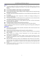
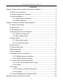
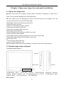
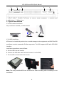
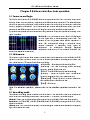
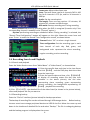
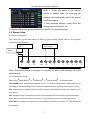
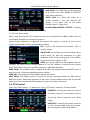
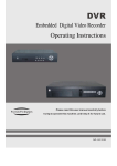
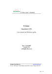
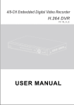
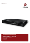
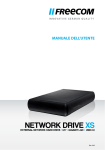
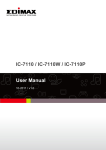
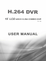
LCD 4/8Channel DVR Quick Manual
0
LCD 4/8Channel DVR Quick Manual
Notes:
The power supply of this DVR is provided through DC12V3A adapter, please check the
power outlet before installation and ensure it can meet the requirements of the
adapter;
Do not place the DVR at a place subject to rain and moisture;
Do not install the DVR at a place subject to violent vibration;
Do not install the DVR at a place subject to direct sunlight, and be far away from high
temperature environment;
The DVR’s back panel should be placed 15cm or more away from other objects or wall
for cooling;
The DVR should work under temperature, humidity and voltage according to its
technical specifications;
The space where DVR is installed should not be stored with corrosive chemicals that
may produce volatile gases to avoid affecting the DVR’s life.
The DVR should be installed in a space without much dust, and the environment
should be kept clean and tidy.
Proper grounding should be guaranteed during operation;
The DVR should be installed to ensure proper connection with other devices.
Please buy HDD from official channel to meet DVR’s long-time and large data reading and
writing requirements.
Statement
This manual only introduces basic operation, and please refers to the E-manual in the
CD for detailed operation.
Please refer to the real product and this manual is just for reference.
Products update without further notice. Nuances of partial functions are permitted
after updating.
Please contact the Customer Service Department for the latest program and
supplementary instruction files.
This manual is applicable to various models, and the specific operation of each
product is not listed here. Users can operate the DVR based on this manual for the
actual products.
We have tried our best to ensure the completeness and accuracy of this manual.
However, due to the unstable environment and other reasons, the real value of some
data may differ. If any problem or dispute arises, the company’s final explanation will
prevail.
If carrying out operation not according to the instruction of this manual, the users
shall bear the losses sustained.
1
LCD 4/8Channel DVR Quick Manual
Contents
Chapter 1 Open-case inspection and quick installation..................................... 3
1.1 Open-case inspection .......................................................................... 3
1.2 Product appearance and port .............................................................. 3
1.3 Quick Installation ................................................................................. 4
1.3.1 DVR combo installation............................................................. 4
1.3.2 HDD installation ........................................................................ 4
Chapter 2 Software interface basic operation ................................................... 5
2.1 Power on and login .............................................................................. 5
2.2 Main menu .......................................................................................... 5
2.3 Recording mode................................................................................... 5
2.4 Recording Search and Playback ........................................................... 6
2.4.1 Search and playback ................................................................. 6
2.4.2 Recording backup ..................................................................... 6
2.5 Alarm Setup ......................................................................................... 7
2.5.1 Alarm basic setup ..................................................................... 7
2.5.2 E-mail alarm setup .................................................................... 8
2.6 PTZ Control .......................................................................................... 8
2.7 Motion Detection ................................................................................ 9
2.8 Network setup ................................................................................... 10
2.9 Port mapping ..................................................................................... 11
2.10 Mobile phone surveillance .............................................................. 12
2.10.1 Mobile phone surveillance ................................................... 12
2.10.2 Mobile Phone end login ........................................................ 12
2.11 Client end and playing software ...................................................... 13
2.11.1 Client end installation & running .......................................... 13
2.11.2 Player .................................................................................... 14
2.12 IE login ............................................................................................. 14
2.12.1 Controls installation download ............................................. 14
2.12.2 IE login .................................................................................. 15
2.13 Central Management Software (CMS) ............................................. 16
Appendix: System Connection Picture............................................................. 18
2
LCD 4/8Channel DVR Quick Manual
Chapter 1 Open-case inspection and quick installation
1.1 Open-case inspection
◆ When you receive the products, please check if the DVR is complete or make sure if
there is any accidental damage during transportation.
◆ Then, please open the package and check if the accessories are complete. You can
remove the protective film of the DVR package.
The Package contains the following accessories:
◎One IR remote controller
◎One pair of remote controller batteries
◎One piece of Product Certificate
◎One piece of product Warranty Card
◎One piece of User Manual
◎One SATA HDD cable (already installed in the case)
◎One DC12V5A power adapter
◎One HDD bracket (already installed) and a set of mounting screws
◎One HDD power supply cable (installed in the case)
◎One piece of CD
◎A set of video expansion wire
◎A set of audio expansion wire
Specific product accessories may be different, so please refer to the real products.
1.2 Product appearance and port
Front and Lateral panel 1:
Hard disk
USB interface
Power in
Keys
1.PWR:Power LED
2.REC:REC indicator 3.LINK:Network connection indicator
4.LEFT、RIGHT、DOWN、UP:The Directional keys of DVR 5.DISP:display mode
6.MENU:Menu 7.ESC:Exit/Return 8.ENTER:Enter
Back panel 1:
3
LCD 4/8Channel DVR Quick Manual
1
2
3
4
1. Power switch 2.Sensor 1-8:Alarm in; Alarm: Alarm out;RS485
4.Audio in/out 5.Video in/out
5
3.Network port
1.3 Quick Installation
1.3.1 DVR combo installation
Easy installation method, as shown below:
1.3.2 HDD installation
HDD must be installed by technicians to avoid damage to the equipment and HDD.The DVR
mainframe must be powered off before operation. The DVR supports HDD with SATA HDD
interface.
Installation procedures are as follows:
A. Put the HDD into the bracket;
B. Connect the HDD date cable well and connect it to the DVR;
C. Fix the HDD on the bracket with screws
Note: The newly installed HDD can be served for video recording after formatting on the
mainframe.
4
4/8Channel DVR Quick Manual
LCD 4/8Channel
Chapter 2 Software interface basic operation
2.1 Power on and login
The DVR’s initial device ID is 000000 without any password, the user can enter main menu
directly. Users can set ordinary password and administrator password. The administrator
directly.
has all the operating privileges, while ordinary users can only carry out monitor and video
search/ playba
playback
ck operations. (The mainframe will match automatically when you enter
password, and different permissions will be given according to different passwords).
If you want to operate in main menu after the password is set, the system will display “user
login” interface:
interface:
Device ID: It is just okay to enter device ID displayed
on the right side in corres
corresponding
ponding input box. The
default ID will be guided when mouse operation is
done
done.. We recommend setting a password when
remote controller is operating many types of
equipment
equipment,, to distinguish through targeted
equipment code input, or the remote controller will
disturb the adjacent mainframe.
2.2 Main menu
Click mouse right button after system startup, and quick operations are available to D
DVR
VR
system in the pop
pop--up
up menu. Users can set or control parameters including main menu, key
lock, video search, PTZ control and video recording.
lock,
【
【Playback
Playback
Playback】
】:: Search detailed
detailed recording files
【 Record 】 : Set the recording mode includ
including
ing
channels, quality, frame rate, etc.
【
【HDD
HDD
HDD】
】:: Check HDD capacity and formatting
【 Setup 】 : Setup of system basic information
including
including language, time, user password, etc.
【
【Advanced
Advanced
Advanced】
】:: Setup of alarm, motion detection,
and mobile phone surveillance, etc.
【
【Exit
Exit】
】:: Exit menu
Note: For detailed operatio
operation,
n, please refer to the detailed operation manual in the
CD.
2.3 Recording mode
The default recording mode used for the first time is the normally open and continuous
video. Enter the Recording mode from “Main menu”
menu”—
—>>“Record”,
“Record”, as shown below:
Channel: Select the corresponding video channel on or off (16ch DVR with 16 channels).
Resolution: D1 (704x576), Half-D1 (704x288) and CIF (352x288), among which D1 is of the
highest resolution.
Quality: best, fine, and normal quality, corresponding to 3 data str
stream
eam standards of highest,
high and medium bit rates
5
LCD 4/8Channel DVR Quick Manual
Frame rate: Adjust video frame rate
Note: The total frame rate for 4 channels DVR is 100
fps, for 8 channels is 275 fps, and for 16 channels is
400 fps.
Audio: Set the record switch.
File length: There are four options -15 minutes, 30
minutes, 45 minutes and 60 minutes.
REC mode: Startup recording and Timing recording
When powered on: starting recording when the DVR is energized (It works only if the
corresponding channel is enabled in the “Channel” option.)
By time: performing recording as scheduled. When “timing recording” is selected, the
“Record Time Configuration” button will appear on the right. Move the cursor here and
press “Enter” to enter the Record Time Configuration screen, as shown below:
Channel: Select "All" or select a single channel
Time configuration: Set the recording type in each
time interval of each day. Red, green, and
background color represent the alarm recording,
regular recording, and not recording.
2.4 Recording Search and Playback
2.4.1 Search and playback
Enter the Video Search screen from “Main Menu” →“Video Search”, as shown below:
1) Enter the specific date and time in the time frame
and click【PLAY】, and the DVR plays back the video
from the input time.
2) Enter the specific date and time, click 【SEARCH】
to display all recording status this day (the time
schedule in the above picture), the red color
representing alarm recording, green representing
normal recording, the background representing no
recording. Select the time and click 【PLAY】, playback the recording.
3) Click 【FILE LIST】, the detailed file of the video listed (as shown in the picture below),
select and playback the file you want to.
2.4.2 Recording backup
Enter the "file list" interface (picture below) for backup operations.
The backup of recording files can be achieved through USB storage device.
Before backup,
the user must insert storage peripheral devices to USB2.0 slot first. Move the cursor up and
down in the interface of detailed file list and select "Backup". The file is undergoing backup
and the backup progress is displayed on the screen.
6
LCD 4/8Channel DVR Quick Manual
Note: 1. When the space of the backup
device is smaller than the recording file
capacity, the system will remind the user of
insufficient space.
2. After finishing backup, exiting from the
backup device directly is ok;
3. Please refer to the operation manual in the CD for network backup.
2.5 Alarm Setup
Alarm port connection
The input side on the back panel of DVR as Figure below, please refer to the physical
interface of the faceplate:
Alarm trigger
Alarm
Power
+
-
G
G
12V
Alarm output
1 2
3
4
5
6
7
8
Alarm input
Note: The above picture is the type of normally on alarm, and normally off is the
opposite way.
2.5.1 Alarm basic setup
Enter from【Main Menu】→【Advanced】→【Alarm Setup】, as shown below:
I/O ALARM: Each channel corresponds to an I / O alarm status, which means that alarm
recording of corresponding channel will be started when one channel alarm input is valid.
ON: indicating that external alarm circuit is open circuit without alarm but closed circuit
with alarm.
OFF: external alarm circuit that is closed circuit without alarm but open circuit with alarm.
Note: When an alarm is valid, a red letter "I" will display on the corresponding screen.
HDD LOSS: On: When the system cannot recognize the HDD, a red logo “H” will display on
the channel.
7
LCD 4/8Channel DVR Quick Manual
HDD SPACE: On: When the remaining space
of the HDD is less than 500M, the DVR will
have alarm indication.
VIDEO LOSS: On: When the video of a
certain channel is lost, this channel will
display in the lower part of the Video
Preview screen: “Video Loss”.
ALARM MANAGEMENT OUTPUT: including
alarm output, buzzer and post alarm recording.
2.5.2 E-mail alarm setup
Email setup Prerequisite: The mainframe must be connected to the WAN. Please refer to
the Chapter Network for network connection.
When motion detection is triggered, the system will capture a picture at the time of
triggering and send it to the corresponding mailbox.
SSL: a secure link transmission protocol. “Off” is
usually chosen.
SMTP PORT: the mailing port of the mailbox server,
usually being 25, with the exception of a few
mailboxes, such as the mailing port of the GMAIL
server whose port number is 465.
SMTP: the server address of the mailbox used, for
example, the SMTP server mailing address of the 163 mailbox is smtp.163.com; please
check this address from your mailbox supplier for different mailboxes.
SEND EMAIL: the mailbox address used to send mails, the above-mentioned SMTP server is
also the server of the corresponding sender address.
SEND PW: the password of the mailbox used to send mails.
RECV EMAIL: the address used to receive the picture transmitted after the DVR motion
detection alarm. Please pay attention to the space of your mailbox timely lest the normal
operation of the mailbox be affected due to an excess number of pictures.
2.6 PTZ Control
Enter from "Main Menu" → "Advanced" to the "PTZ setup" interface, as shown below:
CHANNEL: selecting the channel to which
the dome camera is connected (to select
any of the latter 4 channels, click “Next
Page”)
PROTOCOL: selecting the dome protocol
of the corresponding brand and model,
with two options, Pelco-D by default
8
LCD 4/8Channel DVR Quick Manual
BAUD RATE: selecting the baud rate used by the dome, with the 4 options of 1200, 2400,
4800 and 9600
DATA BIT: with the options of 5, 6, 7 and 8, 8 by default
STOP BIT: with the options of 1 and 2, 1 by default
VERIFY: with the 5 options of None/Odd/Even/Mark/Space, None by default
ADDRESS: Complete the PTZ code of the corresponding channel.
Just set “protocol”, “baud rate” and “address code” in order to set the PTZ.
Click "PTZ control" in the main interface, the following screen will pop up (left picture):
Operate the PTZ with mouse through the keypad on the interface. Set the cruise point in
the cruise setup, as shown on the right picture above.
2.7 Motion Detection
Enter the Motion Detection screen from “Main Menu” →“Advanced” to “Motion
Detection”, as shown below:
STATUS: Each channel has a corresponding
switch. Select “On” or “Off”.
SENSITIVITY: Each channel has a corresponding
sensitivity setting, with the 4 levels of 1, 2, 3
and 4, in which 4 is the highest. Select
sensitivity for confirmation.
MD AREA: Each channel has a corresponding
motion detection area setting. Move the cursor
to “Setup” of the corresponding channel, and press “Enter” to enter the motion area setup
screen of this channel, where a red block indicates motion detection is activated for this
area and a transparent block indicates motion detection is not activated, as shown below.
Motion detection setup procedures:
A.
Turn “On” the corresponding channel in the
“Channel Switch” option;
B.
Set the sensitivity level as necessary, usually set
at 3 or 4;
C.
Set the motion area of the corresponding
channel in the “Area Setup” option;
D. In the “Recording Mode” screen, set the
corresponding channel to “On” in the “Channel”
9
4/8Channel DVR Quick Manual
LCD 4/8Channel
option;
In the “Recording Mode” screen, select “Timing Recording” in the “Recording Mode”
option, also click “Record Time Configuration” to enter the Record Time Configuration
screen and set the corresponding time to alarm recording (see timing recording in
“Recording Mode” for the setup method).
After the setup has been done and motion detection is triggered, a red letter “M” will
appear in the screen of this channel. See “Alarm processes” in Sec
Section
tion 2.5
2.5.1
.1 for alarm
processing.
Operating prompt:
Remote controller operation: Use “ “ (display mode) to select full screen or blank;
Mouse operation: Left
Left--click
click the mouse and drag the motion box to set the area of dynamic
detection.
For detailed operation procedures, please refer to the manual in the CD.
E.
2.8 Network setup
Enter the “Network” screen from “Main Menu” →“Advanced” to “Network Setup”, as
shown below:
TYPE: with 3 options: STATIC
STATIC,, DHCP and PPPOE
TATIC: allocating an IP address manually
STATIC:
DHCP: acquiring an IP address automatically (left picture below)
DHCP:
After selecting the DHCP mode, restart the system after confirmation. After starting, the
system will establish a connection with the DHCP server automatically. When this is
successful, this unit will be allocated with an IP address, which will be displayed on the
screen.
PPPOE: broadband dial-up network access, as shown on the right picture below
PPPOE:
below:
PPPOE name and password
password:: Fill in the PPPOE user name and password provided by the
Internet service provider.
PORT:: the port number used in the private protocol communicatio
communication
n between the
MEDIA PORT
DVR and PC
PC,, usually being 9000 by default. If this port of the PC is occupied by any other
service, please modify it to an
another
other unused port.
WEB PORT
PORT:: the http port, usually being 80 by default. If the administrator modifies the
WEB port to any other port, such as 88, you have to postfix the IP with the port number,
and enter ““http://192.168.1.19:88
http://192.168.1.19:88
http://192.168.1.19:88”” in the address ba
barr when accessing the DVR via the IE.
IP ADDRESS
ADDRESS:: allocating an IP address according to the network environment of the DVR
SUBNET MASK
MASK:: filling in a subnet mask according to the network environment of the DVR
ATEWAY:: Setting the gateway according to the ne
network
twork environment of the DVR. If there
GATEWAY
10
LCD 4/8Channel DVR Quick Manual
is no router device in the network, please allocate an IP address on the same network. If
there is a router device, you have to set the corresponding gateway.
DNS: setting the IP address of the domain name server (DNS varies from city to city); you
can refer to the domain name server configurations of the PC.
UPNP: When the UPNP function is on (UPNP function on the router end is also on), then
the DVR will map the port and IP into the router automatically.
DDNS SETUP
Click “DDNS Setup” to enter the screen (picture below):
DDNS (Dynamic Domain Name Server): with
the two options of “ON” and “OFF”; when a
dynamic domain name server is available,
please select DDNS "ON";
SERVICE: The user may select his/her desired
DDNS server, with the 2 options of 3322 and
dyndn.
HOST NAME: Enter the host name registered
on the dynamic domain name resolution
server;
USERNAME: Enter the user name registered on the dynamic domain name server;
PASSWORD: Enter the password registered on the dynamic domain name server. Please
refer to the detailed manual in the CD for the application of domain name.
2.9 Port mapping
(If the router and DVR both switch on UPNP functions, this step can be saved)
Mapping steps:
1) Set the host IP address, refer to Network Setup.
2) Login the router (taking Cisco router for example). If the IP address of the router is
192.168.1.1 and after this IP has been entered in the IE address bar, a login prompt box will
appear, as shown below:
Click OK to enter the router main interface, click the 【Applications & Gaming】as shown
below:
11
LCD 4/8Channel DVR Quick Manual
Put the DVR's IP and port (WEB port, media
port, phone port) to fill in the corresponding
location, the protocol is “Both”, and the state
is “Enable” or Reboot. Then click “Save
Settings”, add other ports in the same way.
6000 is mobile phone monitoring port, this
port must be added in order to use the mobile
phone surveillance function. As shown above,
9000,80 and 6000 port can all be modified in
the DVR main menu.
2.10 Mobile phone surveillance
2.10.1 Mobile phone surveillance
The mobile phone surveillance function of this series DVR is supported by mobile phones of
the Windows Mobile and Symbian operating systems.
Here you can check the user name and
password of the monitoring video by using
the mobile phone to log in the DVR.
Server port: The setting range is 1024 –
65535. This port needs to be mapped on the
router, and the setting method is the same as
the mapping method of network setting.
User name: admin by default.
Password: empty by default
2.10.2 Mobile Phone end login
Taking the iPhone for example, run the iPhone’s APP Store program and search KMEye, find
the installation package of application program, and click to install.
Open the mobile phone software kMEye. For the first-time use, modify the parameters.
Click 【Settings】 to enter the parameter setting interface (left picture below), and the
default port number is 15961. The user can set other port number on the DVR end. The
default password is empty. Set the parameters well and connect the server, mobile phone
preview interface will display (right picture below):
12
4/8Channel DVR Quick Manual
LCD 4/8Channel
Note: Please refer to the Mobile Phone Surveillance Manual for detailed installation
method and application instruction.
2.11 Client end and playing software
2.11.1 Client end installation & running
Open client end file “
” in the CD and run one of these files. After the
successful installation pr
prompts,
ompts, run the desktop program (NetDvr)
, it will show a login
interface, as shown below:
IP address:
address: enter IP address or domain
name
Media port: enter DVR media port
Pas
Password:
sword:
enter
DVR
network
password and empty by default.
Network:
LAN: If the computer and DVR are in
the same LAN, choose “LAN” mode. In
this mode, the image video transmission format is CIF and frame rate is 25fps.
Internet: If the computer and DVR are in different LAN, choose ““Internet”.
Internet”. In this mode, the
image video transmission format is CIF and the frame rate is 6fps.
Language: Chinese and English are optional.
OFFLINE: open the attached player and play local backup video file.
Note: After successful login, the interface is the same as IE end. Please refer to the
13
4/8Channel DVR Quick Manual
LCD 4/8Channel
manual in the CD for detailed operation.
2.11.2 Player
H.264 format video compression is adopted, and a special player is needed
needed.. Open the
player’s installation program “PlaybackSetup.exe”
“PlaybackSetup.exe” in the CD.
After installing successfully as prompted, run the desktop program (Playback software)
and the player interface will appear
appear:
:
Enter from “Files” →”Open local files”, and open the contents where recording files are
saved. Choose the format as .264, and select and play the recording file required, the
playing recording file will display on the above screen. Corresponding playing operation and
setting can be carried out. Please refer to the manual in the CD for detailed operation
operation..
2.12 IE login
2.12.1 Controls installation download
Firstly, add the IP address of DVR to the system’s trusted sites and operate it according to
the following steps on the XP system. Open the browser, select “Internet options” on the
“Tool” list and then op
operate
erate as below:
14
LCD 4/8Channel DVR Quick Manual
1. Security
2. Sites
5. Enable
4. Add
6. Ok
3. Cancel
After finishing setup, restart the browser. Enter the IP address in the IE address bar
and complete the automatic installation of the plug-in units according to the indication.
2.12.2 IE login
After finishing the plug-in units installation, and then login. For example, the DVR’s domain
name
is
dvrtest01.3322.org
and
the
port
is
88,
enter
http://dvrtest01.3322.org:88 in the IE address bar, as shown below:
15
the
domain
name
LCD 4/8Channel DVR Quick Manual
Password: Enter the IE password of DVR. This
password is set at the Internet end. Please refer to
the manual in the CD for details
Network:
LAN: If the computer and DVR are in the same LAN,
choose “LAN” mode .In this mode, the image video
transmission format is CIF and the frame rate is 25fps.
Internet: If the computer and DVR are in different LAN, choose “Internet”. In this mode, the
image video transmission format is CIF and the frame rate is 6fps.
Language: Chinese and English are optional.
Login: Click to login into DVR internet
Reset: Re-enter the above information
After login, the following real-time preview screen will display. Users can preview at the IE
end and perform the functions of video playback, video setup, alarming setup, etc. Please
refer to the manual in the CD for detailed operation.
2.13 Central Management Software (CMS)
This system supports connection to DVR through Internet, not through the support of
intermediate server. It is convenient for user’s management.
Software installation: Double click to run CD file “DVRCMS.msi”,finish as prompted. After
successful installation, double click desktop icon
following picture:
16
and run software. Display as the
LCD 4/8Channel DVR Quick Manual
【user name】: Create the initial user name for
login
【password】: Create the initial password
【Re-enter】: Confirm the initial password
【 Language 】 : Chinese and English are
optional.
Note: If the earlier version of this software has already been installed, please
manually delete the installation menu “user.cfg”. The default installation menu is
C:\Program Files\DVRCMS\.
Please enter into the main interface of management software after successful login:
System configuration
Lock
Add DVR
Del DVR
DVR
configuration
Playback
DVR list
PTZ control
Recording
Screen split
Capture
Stop video
Volume
In the management software, there are adding device, live preview, video playback, system
setup, advanced setting, PTZ control and so on. Please refer to the detailed instruction of
CMS in the CD for specific operation.
17
LCD 4/8Channel DVR Quick Manual
Appendix: System Connection Picture
18
LCD 4/8Channel DVR Quick Manual
19