1
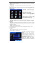
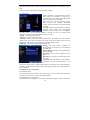
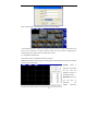
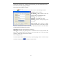
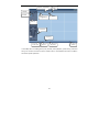
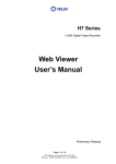
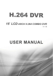
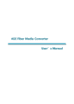
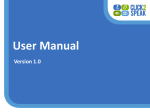
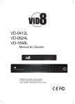
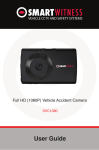
16CH Embedded Digital Video Recorder H.264 User Manual Notes: 1. The power supply of this DVR is provided through DC12V5A adapter, please check the power outlet before installation and ensure it can meet the requirements of the adapter; 2. Do not place the DVR at a place subject to rain and moisture; 3. Do not install the DVR at a place subject to violent vibration; 4. Do not install the DVR at a place subject to direct sunlight, and be far away from high temperature environment; 5. The DVR should be installed in a space without much dust, and the environment should be kept clean and tidy; 6. The DVR’s back panel should be placed 15cm or more away from other objects or wall for cooling; 7. The DVR should work under temperature, humidity and voltage according to its technical specifications; 8. The space where DVR is installed should not be stored with corrosive chemicals that may produce volatile gases to avoid affecting the DVR’s life; 9. Proper grounding should be guaranteed during operation; 10. The DVR shall be installed to ensure proper connection with other devices. Please buy HDD from official channel to meet DVR’s long time and large data reading and writing requirements. Statement: 1. This manual only introduces basic operation, and please refers to the E‐manual in the CD for detailed operation. 2. Products are subject to the real products and this manual is just for reference. 3. Products update without further notice. Nuances of partial functions are permitted before and after updating. 4. Please contact the Customer Service Department for the latest program and supplementary instruction files. 5. This manual is applicable to various models, and the specific operation of each product is not listed here. Users can operate the DVR based on this manual for the actual products. 6. We have tried our best to ensure the completeness and accuracy of this manual. However, due to the unstable environment and other reasons, the real value of some data may differ. If any problem or dispute arises, the company’s final explanation will prevail. 7. If carrying out operation not according to the instruction of this manual, the user shall bear the losses sustained. 1 Contents Chapter 1 Open‐case inspection and quick installation .......................................................... 4 1.1 Open‐case inspection ................................................................................................ 4 1.1.1 Notes .............................................................................................................. 4 1.1.2 Package and accessories ................................................................................ 4 1.3 Quick installation ...................................................................................................... 6 1.3.1 HDD installation ............................................................................................. 6 1.3.2 Connection to the camera and monitor ......................................................... 6 Chapter 2 Software interface basic operation ........................................................................ 7 2.1 Power on and login ................................................................................................... 7 2.2 Main menu ................................................................................................................ 7 2.2.1 Shortcut menu ............................................................................................... 7 2.2.2 Main menu ..................................................................................................... 8 2.3 Recoring setup .......................................................................................................... 8 2.3.1 Basic setup ..................................................................................................... 8 2.3.2 Advanced setup.............................................................................................. 9 2.3.3 Recording schedule ........................................................................................ 9 2.4 Recording playback and backup ................................................................................ 9 2.4.1 Recording playback ........................................................................................ 9 2.4.2 Recording backup ......................................................................................... 10 2.5 Alarm setup ............................................................................................................. 10 2.5.1 Alarm port connection figure ....................................................................... 10 2.5.2 Motion Detection ......................................................................................... 10 2.6 PTZ setup ............................................................................................................. 11 2.6.1 Channel setup .............................................................................................. 11 2.6.2 PTZ Control ................................................................................................... 12 2.7 Network setup ........................................................................................................ 12 2.7.1 Basic setup ................................................................................................... 12 2.7.2 Advanced setup............................................................................................ 13 2.8 Mobile phone surveillance ...................................................................................... 13 2.8.1 DVR end setup.............................................................................................. 13 2.8.2 Mobile Phone end operation ....................................................................... 13 2 2.9 IE end login ............................................................................................................. 14 2.9.1 IE Controls download and installation ......................................................... 14 2.9.2 IE end login ................................................................................................... 15 2.9.3 Playback and download ............................................................................... 16 2.10 Client end and playing software ........................................................................... 17 2.10.1 Client .......................................................................................................... 17 2.10.2 Playing software ......................................................................................... 17 2.11 Central Management Software(CMS) ................................................................... 18 Appendix: System Connection Picture .................................................................................. 20 3 Chapter 1 Open-case inspection and quick installation 1.1 Open‐case inspection 1.1.1 Notes ◆ When you receive the products, please firstly check if the DVR is complete to make sure if there is any accidental damage during transportation. ◆ Secondly, please open the package and check if the accessories are complete. Users can remove the protective film of the DVR package. 1.1.2 Package and accessories The Package contains the following accessories: ◎One IR remote controller ◎One pair of remote controller batteries ◎One piece of Product Certificate ◎One piece of product Warranty Card ◎One piece of User Manual ◎Two SATA HDD cables (already installed in the case) ◎One DC12V5A power adapter ◎One HDD bracket (already installed) and mounting screws, etc. ◎One piece of CD Note: Specific model of the above accessories may differ, so please refer to the list of accessories in the package. 1.2 Product appearance and port 1. Numeric keys 2.Recording 3.POWER:Power LED;ALARM:Alarm indicator;LINK: Network connection indicator;HDD:HDD indicator;REC:Recording indicator 4.PTZ control 5.Fast reverse play 6.Video search/playback stop 7. Play/Fast forward play 8.Main menu 9. Frame by frame backward play 10. Frame by frame forward play 11.Display mode 4 1. Video in 2.Video out 3.Network port 4.Audio out 5.Power switch 6. Alarm out & Alarm in 7.Grounding 8.SPOT output 9.USB port 10.VGA output 11.RS485 12.Power in 5 1.3 Quick installation 1.3.1 HDD installation (1)Open the cover of DVR, fix the HDD into the bracket;. (2) Connect the HDD data and power cable to the HDD; (3)Tighten the screws to fix the HDD in the case; (4)Lock the HDD case. Note: Do not plug HDD when the DVR is on the power state. 1.3.2 Connection to the camera and monitor Connect the signal of camera with a BNC cable to the DVR video input, connect the signal of DVR video output with a BNC cable to the monitor (Please refer to the back panel figure). Connect the RS485A (+) and the B (‐) respectively to corresponding DVR interface with wires, if camera is the PTZ which can be controlled. 6 Chapter 2 Software interface basic operation 2.1 Power on and login When the DVR is power on, the system enters the preview status. If there is video input, the corresponding channel will display monitoring video on the main interfacce. If there is no video input, blue by default. Full screen and multi‐screen switch can be realized through double‐click and right click on the main interface. Right click and enter the shortcut menu, and select Main menu to enter corresponding Main menu interface. When operating on relevant menus, the system will remind the user to login, interface as below (picture on the right): 【User name】: admin by default. 【Password】:The initial administrator password is: 00000000 2.2 Main menu 2.2.1 Shortcut menu Right click the mouse, and shortcut menu pops up: 【Main menu】:System main menu interface 【Single screen】:Click to enter the corresponding channel and display single screen 【Multi screen】:Screen display with options of 4, 9 and 16 screens 【Next screen】:Switch to the next screen channel 【Start / Stop Record】:It is effective after starting the recording setup 【Record Search】:Recording playback and backup is available when entering 【PTZ Control】:enter the PTZ control interface 【Digital Zoom】:Under single‐channel preview screen, when choosing an area, users can enlarge the area 【PIP】:After clicking, main interface will appear and a small screen will 7 display on the lower right corner. 【System Informa】:including the version, network address, system ID, and recording files information, etc. 【System Reset】:including user locking, system restart and system shutdown 2.2.2 Main menu Click mouse right button and select the main menu, main menu interface of DVR system pops up as below: 【 Record 】 : “Basic”includ resolution, quality, frame rate, pre‐Record setup; “Advanced” includ overwrite, overlay; “Recording schedule”: set the recording types of every period every day. 【Alarm】:including Alarm in, Motion Detection, HDD mistake, password mistake and video loss setup. 【 Channel 】 : Select channel and set channel name, PTZ protocol, PTZ Baud Rate, PTZ Address and Color setup. 【Network】:Set IP, port number, DNS and Mobile phone surveillance, etc. 【User】:Add, modify and delete users and set the user privileges. 【System】:including Basic setup, Advanced setup, HDD management, and System Maintenance. 【Display】:Main display switching interval, ignoring video loss, and display resolution setups. 【Log】: Information regarding login and starting system will be kept. Users can view the system log information. 【Exit】:Exit from system main menu Note: For detailed operation, please refer to the detailed operation manual in the CD. 2.3 Recoring setup 2.3.1 Basic 【Main menu】【Record】,enter the basic setup Interface: 【Resolution】:CIF, Half‐D1 and D1; 【Quality】:Recording quality is divided into lowest, low, normal, high, and highest quality. 【Frame Rate】:Refer to the frames per second of encoding. 6, 12 and 25 frames respectively under PAL system, and 1, 15, 30 frames under NTSC system. 【 Audio 】 Refer to the audio channel of related video. Mouse click and the drop‐down box pops up, and there are 1‐4 8 audio channels to choose.(The DVR without audio has no this potion) 【Pre‐Record】:Refer to the encoding frames per second before trigger alarm and after finishing alarm event when one channel is set to be timer & alram recording. 【Copy To】:After setup the parameters of a centain channel and all parameters of other channels are consistent with this channel, the parameter of this channel can be copied to other channels through this function. 2.3.2 Advanced 【Overwrite】:Select Yes. when the capacity of HDD is full, the new recording file will overwrite the earliest recording file. If selecting No, it will not record for insufficient space. 【Overlay】:select Yes,the playback screen will display time and date when playback the recording file; select No, it will not display the time and date. 2.3.3 Plan “Plan” interface including not recording, timer recording, alarm recording as well as timer & alarm recording setup. Plan is divided into 7 days a week and 1 hour per period one day. Users can set the recording type of every period every day. After the parameters are set and saved, copy to the other channels. 2.4 Recording playback and backup 2.4.1 Recording playback Select【Record search】from shortcut menu and enter the interface, with two type of Search by type and Search by time. By Type: with 5 options of All, manual, timer, alarm, timer & alarm. Select the type that you want to search in the drop‐down box, and choose from the recording list form the left 9 picture below. By Time: enter the specific time, and detailed file list as the above right picture will pop up. Select and playback. 2.4.2 Recording backup In the "Detailed file list" (left picture above) , select the recording file to backup. If selecting single file backup, the interface as the following picture(on the left)w will pop up; for multiple files backup, select multiple files and click “multiple files backup”. The progress of recording backup as shown in the following picture( on the right): Note: 1. DVD‐RW or USB flash disk is optional for recording devices. 2. Do not exit or power off during backup, or it will affect the backup of recording file. 3. Please see the detailed operation manual in the CD. 2.5 Alarm setup 2.5.1 Alarm port connection figure The input side on the back panel of DVR shown as Figure below, please refer to the physical interface of the faceplate: Alarm trigger Alarm Power 2 3 4 5 6 7 8 + ‐ G 12V G 1 Alarm output Alarm input Note: The above is the 1CH alarm in and 8CH alarm in figure. The back panel of 16CH is 4CH alarm out and 16CH alarm in with the same priciple. The above is the normally on status connection figure, and normally off status is in the opposite way. 2.5.2 Motion Detection 10 The setup method of motion detection is the same as the setup of alarm in. Please refer to the detailed instructions in the CD. The setup method of sensitivity and motion detection area will be introduced (picture below). Sensitivity refers to the motion detection sensitivity which can be set when the recording mode is motion detection or motion detection & alarm recording. Choose the sensitivity from the drop‐down list, and confirm and save the parameter. Setting procedures: 1. Select channel, sensitivity and detection areas. Sensitivity is off by default with 1‐9 options. Detection areas are all by default. 2. Save the parameters and set recording schedule by time. (Please see the 2.3.3 recording schedule for reference.) (1) Select partial areas in the detection area column on (1) the motion detection interface. (2) On the motion detection interface(left picture), draw the areas to be detected. Red blocks represent activated areas, while transparent blocks represent unactivated areas. Confirm and save the parameters after successful setting. . 2.6 PTZ setup 2.6.1 Channel setup Enter from the Main menu to Channel setup. The channel setup interface contains the channel No., channel name, PTZ protocol, PTZ baud rate, PTZ address and color setup. 【Video channel】: Select the channel. 1‐16 is optional. 【Channel Name】: Enter the channel name. Chinese, English, digit and special characters can be entered. 【PTZ protocol】: It’s used to achieve the communication with the PTZ. Mainly supported baud rate: PTZ‐NULL, LG LPT‐A100L, PELCO‐D, NK‐97CHE, SAMSUNG SCC‐641, and PELCO‐P, etc. 【PTZ Baud Rate】: Select an appropriate baud rate. 11 【PTZ ID】: PTZ address code range is 0‐255. 【Color】: Through the brightness, contrast, saturation, chromaticity setup to adjust channel display effect. 2.6.2 PTZ Control Right‐click to enter the preview screen and select "PTZ control" in the pop‐up shortcut menu, and enter the PTZ control interface (below): Directional buttons are used to control the moving direction of dome. PTZ button can control automatic rotation of comon PTZ. Lens zoom, focus, IRIS can be adjusted respectively by using increase "+" reduce "‐" buttons. PTZ’s moving speed is adjustable and the value range is 0 ~ 9. Use the preset: enter the corresponding preset value and the dome lens can be adjusted to the appropriate position; set the preset position: Enter the corresponding preset number , the targeted position of the dome camera can be set as preset points. Click the “Record tracking” on the interface ( the button will display “end record” after clicking). Click the "Start tracking" (after clicking, it changes to "End tracking"). The PTZ will operate according to track set and click the "End tracking", and the PTZ will stop. 2.7 Network 2.7.1 Basic Enter from the Main menu to Network setup. Network setup is divided into Basic setup and Advanced setup. Basic setup interface mainly includes network access mode, IP address, subnet mask, gateway address and other parameters, as shown below: 【Connect mode】:with two types of static IP and dynamic IP. IP address, gateway address and subnet mask should be entered manually for the static IP. Dynamic IP is the IP allocated by DHCP server. 【NTP Server】:Set the time and correct the server address to achieve the time synchronization of DVR. 【HTTP Port】:WEB port , generally the default value is 80. If modifying the WEB port into other ports, such as 88, users need to add the port numble. When using IE to visit the DVR, enter http://192.168.1.19:88 in the address bar. 【Media Port】:The port number adopted when there is private protocol between DVR and PC end. When ex‐factory, the DVR has a default value. If this port is occupied by other Services , modigy it to an unused port. 12 【Intercom port】:Port to realize the intercom function between remote device and the DVR Note: The range of above ports is between 1024 and 65535. 2.7.2 Advanced 【Minor stream】:Set image quality and frame speed. When the network is not good, the secondary stream can reduce the image quality and frame rate and open by default. Note: Users can’t set the secondary stream, video channels and resolution themselves because the three functions are default settings of system. 【Email】:Support email alarm when an event is triggered, DVR system will automatically intercept the pictures when an event is triggered and then send it to the specified mailbox to prompt the users. For specific setup procedures, please refer to the detailed operation in the CD. 【DNS】:Set the IP of DNS server's 【Mobile】:Set the phone access port 【DDNS】:DDNS is a Dynamic Domain Name Server. Set DDNS type, server address, domain name, user name and password, as shown in the picture below ( Please refer to the detailed manual in the CD for application method of domain name) DDNS Type:with options of 3322.org and dyndns.org Service : the server address providing the dynamic domain name service, corresponding to the DDNS type Domain Name:the domain name applied by the user for the DVR User Name: the user name registered on the DDNS Password: the password corresponding to the user name 【UPNP】: When the UPNP is on (the UPNP at the Router is also on), the DVR host will map the port and IP automatically to the Router. Note: If the Router doesn’t support UPNP, please manually map the corresponding port from the port forwarding or virtual server. If conflicting with other ports, please modify the port on the DVR. 2.8 Mobile phone surveillance 2.8.1 DVR end setup First select the "Advanced Setup" in the "Phone setup" to enter mobile phone monitoring interface and set the port. The port range is 1024‐65535. 2.8.2 Mobile Phone end operation Taking the iPhone for example, run the iPhone’s APP Store program, switch to the Search 13 tab in the search bar and enter kMEye; find the installation package of application program, and click to install. Open the mobile phone end software kMEye. For the first‐time use, modify the parameters. Click 【Settings】 to enter the parameter setting interface (left picture below), and the port number is the number set in Section 2.9.1. The user can set their own port number on the DVR end. The port number is 6000 and the password is 00000000 by default when ex‐factory. Set the parameters well and connect the server, mobile phone preview interface will display(right picture below) : Note: Please refer to the Mobile Phone Surveillance Manual for detailed installation method and application instruction. 2.9 IE end login 2.9.1 IE Controls download and installation Firstly, add the IP address of DVR to the system’s Trusted sites and operate it according to the following steps on the XP system. Open the browser, select “ Internet options” on the “Tool” list and then operate as below . 1. Security 14 2. Sites Note:The fifth step can add the DVR’s domain name or the IP address (For detailed application procedures of DVR ‘s domain name, please refer to the manual in the CD). 2.9.2 IE end login After setting the Trusted sites, reboot the browser and install the plug‐in units as prompted. After installation, the login interface is shown as below. Enter he login port number, user name, password, and selected language, click "OK" and then remote access to DVR is available. 15 After successful login, the following preview screen will display: In the preview interface, target at the video window and click the right mouse button, and then you can switch on or off the preview video and audio channels. Regarding the detailed operation, please refer to the manual in the CD. 2.9.3 Playback and download Click LIVE and enter the playback interface as below: Search: Select Video search by type, the video file list will display with two options of Video search by time and by type. PlayFile: Select a video file in the video file list, click and playback. Operate in the plaback screen. Download: Select the file and click to download. specific 16 For operation, please refer to the manual in the CD (During downloading, the video playback will pause). 2.10 Client end and playing software 2.10.1 Client end installation & running Open the“ ”of “Client end “ in the CD, as shown in the following interface: DVR Addr:DVR’s IP address Use Domain : When selected, enter the domain name in the DVR address bar DVR Port:DVR media port Username:Enter DVR’s user name Password:Password corresponding to the user name Minor Stream:When selected, the DVR’s internet will transmit in secondary stream; otherwise, the DVR will transmit in main stream. Secondary stream for external network and main stream transmission for intranet. Language:alternative language choices at client end Off‐line:After selected, only playing function is available and users can play local video files Note:After successful login, the interface is the same with the IE end. For specific operation, please refer to the manual in the CD. 2.10.2 Playing software The video adopts H.264 compression format, so special playing software is needed. Open the player file "player.exe"( ) in the CD, as shown below: 17 Note:Please refer to the Manual in the CD for detailed operation of the player. 2.11 Central Management Software (CMS) This system supports connction to DVR through Internet, not through the support of intermediate server. It is convenient for user’s management. Software installation: Double click to run CD file “DVRC MS. msi”, and finish as prompted. After successful installation, double click desktop icon and run the software. As shown in the folloing picture: 【User name】: Create the initial user name to login 【Password】: Create the initial password 【Re‐enter】: Confirm the initial password 【Language】: Chinese and English are optional. Note: If the earlier version of this software has already been installed, please manually delete the installation menu“user.cfg”. The installation menu by default is C:\Program Files\DVRCMS\. Please enter the main interface of CMS after successful login: 18 System configuration Lock Add DVR Del DVR DVR configuration Playback DVR list PTZ control Recording Screen split Capture Stop video Volume In the CMS, there are adding device, live preview, video playback, system setup, advanced setup, PTZ control and other functions. Please refer to the detailed instruction of CMS in the CD for specific operation. 19 Appendix: System Connection Picture 20 21