1
Function
3.2.3
Automatic self test
The device automatically carries out a self test after connecting to the
system to be monitored and later every hour. During the self test internal functional faults are detected and will appear in form of an error
code on the display. The alarm relays are not checked during this test.
By default, K1 signals the faults detected.
3.2.4
Manual self test
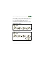
After pressing the internal test button for > 1.5 s, a self test is performed
by the device. During this test, functional faults will be determined and
appear in form of an error code on the display. The alarm relays are not
checked during this test.
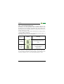
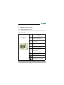
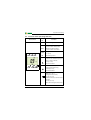
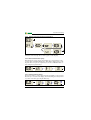
While the test button T is pressed and held down, all device-related display elements are indicated on the display.
3.2.5
Functional faults
If an internal functional fault occurs, all three LEDs flash. An error code
will appear on the display (E01...E32).
For example, E08 means: Incorrect internal calibration. In such a case
please contact the Bender Service.
3.2.6
Fault memory
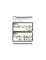
The fault memory can be deactivated. A stored fault can be deleted by
pressing the reset button "R".
3.2.7
Assigning alarms to the alarm relays K1/K2
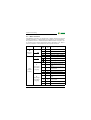
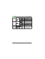
Different alarm categories can be assigned to the alarm relays K1/K2 via
the menu "out".
3.2.8
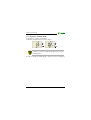
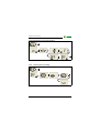
Time delays t, ton and toff
The times t, ton and toff, described below, delay the output of alarms via
LEDs and relays.
12
TGH1413en/09.2007