1
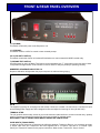
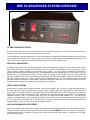
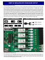
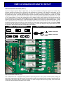
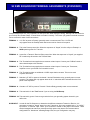
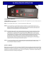
OVERVIEW M2 Antenna Systems, Inc. Model No: S2 Sequencer TROUBLESHOOTING INSTALLATION Operating Instructions SPECIFICATIONS WARRANTY ADDENDUM MODEL NUMBER ........................................... EME SEQUENCER S2 POWER REQUIREMENTS. ............................ 86-264VAC / 1AMP HOT SWITCH SECURITY ............................... DPDT Relay / Latching ENCLOSURE SIZE ......................................... W=6.25”/ H=2.25” / D=8” COLOR ........................................................... Black Anodized RELAY CONTROL OUTPUTS ........................ (4) RX Selectable / (4) TX Selectable No Jumper = Open Circuit (No State) A to B Jumper = Ground (On TX) B to C Jumper = +13VDC (On TX) SEQUENCER DELAY ..................................... With Jumper = ~80 Milliseconds Without Jumper = ~120 Milliseconds CONTROLS .................................................... Power Switch / Preamp Switch / Polarity Switch PLEASE READ BEFORE USE AND SAVE M2 Antenna Systems, Inc. 4402 N. Selland Ave. Fresno, CA 93722 Tel: (559) 432-8873 Fax: (559) 432-3059 Web: www.m2inc.com ©2015 M2 Antenna Systems Incoporated 06/01/15 Rev.00 FRONT & REAR PANEL OVERVIEW I / O (POWER) This button controls AC power to the Sequencer unit. I / O (PREAMP) This button controls +12VDC to control a mast mounted preamp. V & H (POLARITY SWITCH) This switch controls the Vertical or Horizontal Polarization to a mast mounted 24-28VDC coaxial relay. T (PREAMP TEST SWITCH) If an M2 preamp is used, the Noise Test feature can be operated by the “T” push button on the front panel. Noise Test provides an approximate 10 db increase in receiver noise to verify the preamp is operating correctly. NUMBERED SEQUENCE INDICATORS 1-4 Sequence indicators will light when the proper sequence is achieved during keying. AC IN The supplied (3) prong AC cord plugs into this socket. Connect to a reliable 110 VAC source. The Main AC input and switching power supply have been designed to filter and adjust for incoming AC from (86-264 VAC). TERMINAL STRIP The (10) position terminal strip, serves as your multi-conductor cable interface to a tower mounted relay / preamp system. A ground connection on terminal (10) has been provided for shielded cables. DISCONNECT THE AC POWER CORD WHEN CONNECTING CABLE LEADS. XCVR INPUTS (TRANSCEIVER) In order for the S2 Sequencer to determine the difference between Transmit or Receive, it is necessary to supply a “Keyed” state from your Transceiver. We have supplied both a “+2-12VDC” input and a “To Ground” input. Check your Transceiver manual for the proper connections. Most modern Tranceiver’s “Key to Ground.” EME S2 SEQUENCER SYSTEM OVERVIEW S2 EME SEQUENCER THEORY If you have ever blown up your new GasFET preamp or hard-to-find coaxial relay, or are just plain worried about It, this transmit / receive Time Delay Generator/Sequencer is the answer. The S2 Sequencers’ primary application is for VHF/UHF transverter, amplifier and antenna switching. But it can be used in any amplifier antenna scheme. An enable signal to the sequencer will produce sequential output commands to a RX relay, a TR relay, an amplifier and a transverter automatically, plus a polarity change lockout. WHY USE A SEQUENCER ? In stations using transverters, extra power amplifiers and external antenna mounted TR relays, several problems may arise. When the exciter is switched into transmit by the PTT or VOX line, it immediately puts out a ground (or in some cases a positive voltage) command for relay control and RF signal. If a control signal is supplied to the transverter, amplifier and antenna relays simultaneously, RF can be applied as the relay contacts bounce. In most cases, RF will be applied before a relay can make full closer. This can easily arc contacts on DC and RF relays and cause permanent damage. In addition, if the TR relay is not fully closed before RF from the power amplifier is applied, excessive RF may leak into the receive side of the relay. The likely result...preamplifier failure. The TR (Transmit/Receive) time-delay generator supplies commands, one after another, going into transmit and going back to receive from transmit, to turn on all station relays in the right order, eliminating the problems just described. HERE’S HOW IT WORKS Assume we’re in receive and are going to transmit. A customer selectable (+2 to +12VDC) or ground command to one of the relays turns it off. This allows a capacitor to charge through a resistor raising the voltage applied to all positive inputs through the IC. The ladder network on all negative inputs sets the threshold point of each comparator at a successively higher level. As the capacitor charges up, each comparator will sequentially change output states. The outputs drive transistors which are “off” in the receive mode. Drive from the gates turns these transistors “on.” This causes the collectors of the transistors to go low, allowing the base-to-emitter junctions to be forward-biased through the (4) LED’s to turn on the relays in sequential order. The LED’s serve as a built-in indicators to check performance and sequencing of the generators. This is convenient if any state changes are made. WHY OUR SEQUENCER IS DIFFERENT M2 Inc. has looked at many sequencer concepts and has determined the biggest problem...hot switch (During Transmit) security. We have integrated a security relay into the sequencer that DISABLES the front panel vertical / horizontal polarization switch when the sequencer is keyed. This security relay will save costly repairs or replacements to your high quality RF power relays. EME S2 SEQUENCER STANDARD SETUP EME S2 SEQUENCER OUTPUTS The S2 Sequencer has (4) independent relays of which (2) independent states per relay output can be selected. In the TX (Transmit) Mode (B2-B5) jumpers can be setup for a “Open Circuit”, “Short to Ground” or “+13VDC output.” In the RX (Receive) Mode (A5-A2) jumpers can also be setup for a “Open Circuit”, “Short to Ground” or “+13VDC output.” In the TX (Transmit) Mode the sequence is output terminals 2-3-4-5. In The RX (Receive) Mode the sequence is output terminals 5-4-3-2. Note that in the RX (Receive Mode) that the delay starts with terminal 5 and works back to terminal 2. For jumper format see diagram “A” below. Diagram “D” shows each jumper location for either TX (Transmit) Mode and RX (Receive) Mode. The TX (Transmit) Mode is factory set as “To Ground” state on B2, B3, B4 and B5. Note if a situation arises where one terminal will have a “To Ground” state and two different voltage values are tied to the same terminal, you must install voltage steering diodes. A standard 1N4004 can be used for this application. See Diagram “C” for information. To make any changes to the jumper selections, loosen the screws on the front and rear panel and slide the cover forward. *A new jumper selection for “Standard” usage and “Map 65” applications has been included in the S2 Sequencer. The S2 Sequencer is shipped with the “Standard” jumper setting described in Diagram “B”. Diagram “A” Jumper Designation A B C A B C A B C OPEN GROUND + 12VDC Diagram “B” Standard Jumper Designation E F G E F G H I J K STANDARD STANDARD STANDARD STANDARD Diagram “C” Steering Diode Example +12VDC Component A2 (TX) +28VDC Component A5 (RX) Diagram “D” B5 (TX) A4 (RX) B4 (TX) A3 (RX) B3 (TX) A2 (RX) JP1 B2 (TX) “B” “B” EME S2 SEQUENCER DELAY (JP1) The S2 Sequencer has an adjustable delay between sequencing. With the (JP1) jumper installed (factory setting) the total delay is approximately 80-milliseconds. By removing the jumper, the total delay would change to approximately 120 milliseconds. See Diagram “D” for component location. To make a change to the time delay jumper, loosen the screws on the front and rear panel and slide the cover forward. EME S2 SEQUENCER MAP 65 SETUP EME S2 SEQUENCER OUTPUTS (MAP 65) If you are using the popular “Map 65” application, you may need an additional configured output for an isolation relay. We have provided a secondary set of jumpers for this application on the board. In the “Map 65” configuration, the first DPDT (RY6) relay has its contacts separated with a jumper. The constant +13VDC on terminal “1” is now activated by the contacts of the relay. In the RX (Receive) Mode +13VDC is present. When the S2 Sequencer is keyed, the +13VDC is removed. Terminal “2” is then used for the isolation relay in a keyed state during RX (Receive) Mode and a N.O. state in TX (Transmit) Mode. To setup this configuration, refer to Diagram “B” for jumper settings. *Note that the jumper has been removed from the first output marked “Open” (RY6-TX Jumper) towards the bottom right of Diagram “D”. All other outputs for RX (Receive) Mode and TX (Transmit) Mode are handled in the same way as the standard outputs. *Please refer to Standard setup for more details. Note if a situation arises where one terminal will have a “To Ground” state and two different voltage values are tied to the same terminal, you must install voltage steering diodes. A standard 1N4004 can be used for this application. See Diagram “C” for information. To make any changes to the jumper selections, loosen the screws on the front and rear panel and slide the cover forward. Diagram “A” Jumper Designation A B C A B C A B C OPEN GROUND + 12VDC Diagram “B” Map 65 Jumper Designation E F G E F G H I J K STANDARD STANDARD STANDARD STANDARD Diagram “C” Steering Diode Example +12VDC Component A2 (TX) +28VDC Component A5 (RX) Diagram “D” B5 (TX) A4 (RX) B4 (TX) A3 (RX) B3 (TX) A2 (RX) JP1 OPEN “B” “B” EME S2 SEQUENCER DELAY (JP1) The S2 Sequencer has an adjustable delay between sequencing. With the (JP1) jumper installed (factory setting) the total delay is approximately 80-milliseconds. By removing the jumper, the total delay would change to approximately 120 milliseconds. See Diagram “D” for component location. To make a change to the time delay jumper, loosen the screws on the front and rear panel and slide the cover forward. S2 EME SEQUENCER TERMINAL ASSIGNMENTS (STANDARD) Terminal assignments are very important, so take your time when doing the wiring. Damage can be caused to your Preamp and Power Relays if connections are made incorrectly. The Green (10) position terminal connector can be removed for ease of wire connections. TERMINAL 1: +13 VDC to power a Preamp, generally tower or mast mounted. The +13 VDC will only appear when the Preamp switch has been turned on from the front panel. TERMINAL 2: This is the Preamp control line. When the sequencer is “Keyed”, this line will put a Preamp in a NON operating state for Transmit. TERMINAL 3: Is used for a Transmit / Receive Relay control line. When the sequencer is “Keyed” your supplied RF coaxial relay will switch to the Transmit State. TERMINAL 4: This Terminal has been supplied as a customer related output. Connect your PA Bias Control or other related output to this terminal. TERMINAL 5: This Terminal has been supplied as a customer related output. Connect your Transverter, Amplifier or even your Exciter if a foot switch is used. TERMINAL 6: This Terminal provides an additional +13VDC output that is constant. This can be used to power other items. TERMINAL 7: Switched +27 VDC to power a Horizontal / Vertical Polarization relay, generally tower or mast mounted. The voltage will only appear when the H / V switch has been activated from the front panel of the Sequencer. TERMINAL 8: Constant +27 VDC to power a Transmit / Receive Relay generally tower or mast mounted. TERMINAL 9: This terminal is for the “Test” feature if you are using the M2 Preamp. TERMINAL 10: This terminal is ground. Connect a ground wire from your grounding system located in your radio room. XCVR INPUT: In order for the S2 Sequencer to determine the difference between Transmit or Receive, it is necessary to supply a “Keyed” state from your Transceiver. We have supplied both a “+2-12VDC” input and a “To Ground” input. Check your Transceiver manual for the proper connections. These terminal assignments match our preamps and high power relay boxes. We recommend this configuration for “Homebrew” switching designs also, but your configuration may vary. S2 EME SEQUENCER TERMINAL ASSIGNMENTS (MAP 65) Terminal assignments are very important, so take your time when doing the wiring. Damage can be caused to your Preamp and Power Relays if connections are made incorrectly. The Green (10) position terminal connector can be removed for ease of wire connections. TERMINAL 1: +13 VDC to power a Preamp generally tower or mast mounted. The +13 VDC will only appear when the Preamp switch has been turned on from the front panel. TERMINAL 2: This is for an isolation relay. When the sequencer is “Keyed”, the isolation relay will switch to a N.O. state. TERMINAL 3: Is used for a Transmit / Receive Relay control line. When the sequencer is “Keyed” your supplied RF coaxial relay will switch to the Transmit State. TERMINAL 4: This Terminal has been supplied as a customer related output. Connect your PA Bias Control or other related output to this terminal. TERMINAL 5: This Terminal has been supplied as a customer related output. Connect your Transverter, Amplifier or even your Exciter if a foot switch is used. TERMINAL 6: This Terminal provides an additional +13VDC output that is constant. This can be used to power other items. TERMINAL 7: Switched +27 VDC to power a Horizontal / Vertical Polarization relay generally tower or mast mounted. The voltage will only appear when the H / V switch has been activated from the front panel of the Sequencer. TERMINAL 8: Constant +27 VDC to power a Transmit / Receive Relay generally tower or mast mounted. TERMINAL 9: *This terminal is NOT USED in the “Map 65” configuration. TERMINAL 10: This terminal is ground. Connect a ground wire from your grounding system located in your radio room. XCVR INPUT: In order for the S2 Sequencer to determine the difference between Transmit or Receive, it is necessary to supply a “Keyed” state from your Transceiver. We have supplied both a “+2-12VDC” input and a “To Ground” input. Check your Transceiver manual for the proper connections. These terminal assignments match our preamps and high power relay boxes. We recommend this configuration for “Homebrew” switching designs also, but your configuration may vary. S2 SEQUENCER OPERATION S2 SEQUENCER OPERATIONS *PLEASE NOTE: During initial setup / testing, ensure that no RF is applied until you are confident that all of your devices are functioning properly. STEP 1: Turn the Power switch to the “ I” position and the power LED will light. STEP 2: If you are planning to use a Preamp for Receive operations, turn the Preamp switch to the “ I” position and the power LED will light. The Sequencer is now in the Receive state. This means that the preamp is powered, a coaxial relay is in Receive state and a Vertical / Horizontal coaxial relay can be switched to your desired polarization from the front panel switch. STEP 3: To Transmit, Key your Mic and note that the Sequencer will run through it’s switching process starting with LED indicator 1 and continuing through to LED indicator 4. When the Sequencer is in the Transmit state, your supplied Preamp has now been switched to NON operation via the control line disconnecting it from the antenna. Your supplied Transmit / Receive relay has now been switched to Transmit state and a Your supplied Vertical / Horizontal Polarization relay has been locked out to keep the system from being “Hot Keyed.” If you would like to change the Polarization via the Vertical / Horizontal switch, release the Mic Key and then switch to your desired orientation. Note that the Polarization switch will stay in the desired orientation whether you are keying or not. This is achieved through a DPDT dual coil latching relay inside the Sequencer. STEP 4: To return back to Receive mode, release the Mic Key and each relay and a Preamp will return back to it’s original starting state. Note again that the Vertical / Horizontal Polarization indicator will stay locked in whatever orientation it was left in. NOTES TO CONSIDER Based upon your location, the location of the moon and Faraday effects it may take some playing around with the Polarization that works best for you at any given time frame. You may find that different times of the day or night may cause you to switch your polarization. You may also find based upon conditions that you may need to switch polarization to the opposite state where reception is best. This is caused by a combination of “Spacial Polarity” of each station and the effects of Faraday Polarity Rotation. WARRANTY INFORMATION 12 Month Limited Warranty This warranty gives you specific legal rights. You may also have other rights which will vary from state to state or province to province. M2 warrants the EME SEQUENCER S2 controller unit against defects in material and workmanship for a period of 12 months from date of purchase. During the warranty period, M2 will, at its option, either repair or replace products or components which prove to be defective. The warranty shall not apply to defects or damage resulting from: Improper or inadequate maintenance by user Improperly prepared installation site Unauthorized modifications or misuse Accident, abuse, or misapplication Normal wear M2 specifically does not warrant this product for any direct, indirect, consequential, or incidental damages arising from the use or inability to use the product. Some states or provinces do not allow the exclusion or limitation of liability for consequential or incidental damages so the above limitation may not apply. In the event repair or replacement are necessary, purchaser shall contact M2 for return authorization. In many cases this contact can simplify and expedite the repair / replacement process and help reduce costs and downtime. The purchaser shall be responsible for packing the product properly for return and for charges to ship the product to M2. Always include with the shipment, a statement detailing the problem / failure and any other pertinent observations. Insuring the product for shipment is recommended. Use the original packing materials whenever possible. M2 is responsible for charges (in the United States) to return the repaired / replacement product only where warranty service is involved. M2 Antenna Systems, Inc. 4402 N. Selland Ave. Fresno, CA 93722 (559) 432-8873 Fax (559) 432-3059 Web: www.m2inc.com EME S2 SEQUENCER PARTS LIST 08-27-14 DESCRIPTION ........................................ QTY EME S2 SEQUENCER CONTROLLER .......... 1 POWER CORD ............................................... 1 JUMPER, 2-POSITION .................................. 4 USER MANUAL .............................................. 1 M2 ANTENNA SYSTEMS, INC. 4402 N. SELLAND AVE. FRESNO, CA 93722 (559) 432-8873 FAX: 432-3059 www.m2inc.com Email: [email protected]