1
EME S2 SEQUENCER SYSTEM OVERVIEW
S2 EME SEQUENCER THEORY
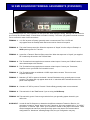
If you have ever blown up your new GasFET preamp or hard-to-find coaxial relay, or are just plain worried about It, this
transmit / receive Time Delay Generator/Sequencer is the answer.
The S2 Sequencers’ primary application is for VHF/UHF transverter, amplifier and antenna switching. But it can be used
in any amplifier antenna scheme. An enable signal to the sequencer will produce sequential output commands to a RX
relay, a TR relay, an amplifier and a transverter automatically, plus a polarity change lockout.
WHY USE A SEQUENCER ?
In stations using transverters, extra power amplifiers and external antenna mounted TR relays, several problems may
arise. When the exciter is switched into transmit by the PTT or VOX line, it immediately puts out a ground (or in some
cases a positive voltage) command for relay control and RF signal. If a control signal is supplied to the transverter,
amplifier and antenna relays simultaneously, RF can be applied as the relay contacts bounce. In most cases, RF will be
applied before a relay can make full closer. This can easily arc contacts on DC and RF relays and cause permanent
damage. In addition, if the TR relay is not fully closed before RF from the power amplifier is applied, excessive RF may
leak into the receive side of the relay. The likely result...preamplifier failure. The TR (Transmit/Receive) time-delay
generator supplies commands, one after another, going into transmit and going back to receive from transmit, to turn on
all station relays in the right order, eliminating the problems just described.
HERE’S HOW IT WORKS
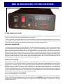
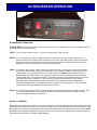
Assume we’re in receive and are going to transmit. A customer selectable (+2 to +12VDC) or ground command to one of
the relays turns it off. This allows a capacitor to charge through a resistor raising the voltage applied to all positive inputs
through the IC. The ladder network on all negative inputs sets the threshold point of each comparator at a successively
higher level. As the capacitor charges up, each comparator will sequentially change output states. The outputs drive
transistors which are “off” in the receive mode. Drive from the gates turns these transistors “on.” This causes the
collectors of the transistors to go low, allowing the base-to-emitter junctions to be forward-biased through the (4) LED’s
to turn on the relays in sequential order. The LED’s serve as a built-in indicators to check performance and sequencing
of the generators. This is convenient if any state changes are made.
WHY OUR SEQUENCER IS DIFFERENT
M2 Inc. has looked at many sequencer concepts and has determined the biggest problem...hot switch (During Transmit)
security. We have integrated a security relay into the sequencer that DISABLES the front panel vertical / horizontal polarization switch when the sequencer is keyed. This security relay will save costly repairs or replacements to your high
quality RF power relays.