1
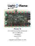
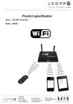
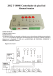
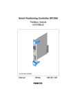
Product specification
Name:WiFi LED Controller
Model:WF300
I. Product Summarization
1. Product constitute
1. LED-WiFi Controller
It is the core of product, responsible for receive control signal
and control LED equipment.
2. RF remote control
In the condition of not use the mobile phone as remote control,
you can choose RF remote control to control LED.
3. A disk
Include IOS operating system and Android operating system
mobile soft.
2. Summarization
LED-WiFi controller is following the traditional with infrared, RF technology controller foundation, it is
birth of market and customer's demand, it is one type controller which integration the newest wifi technical
in the market. It makes the LED control more convenience, more hommization. We can use an Android
system or IOS system mobile phone to install control software, then it can control LED, this is the wishes
of every customer.
Use WiFi technology can make our control range more wider, can get rid of narrow space constraint,
in building can control more than 50m, in outdoor can control more than 100m.
In the condition of not use the mobile software, also can use the remote control to control, very
convenience, bring many choices for you.
II. Technical Parameters
1. Remote control technical parameters
1:Working temperature:-20-60℃
2:Power supply method:AAA*3
3:Supply voltage:1.5V*3
4:Standby power:0.015mW
5:Standby current:3uA
6:Working current:200uA
7:Emission current:10mA
8:Remote control distance:about 30m
9:Standby time:6 month
2. Software technical parameters
1:Name:Magic Color
2:Runtime platform: Android version support Android system(better one can support Samsung,
HTC), IOS version support IOS system, equipment must have WiFi function.
3:Language: English
4:Category: communications
5:Free, green, no plug-ins
3. Controller technical parameters
1:Working voltage: DC5--24V
2:Output control: SPI signal output
3:Output current: 4A*3
4:Connect mode: SPI signal wires(DATA, CLK)
5:External dimension: L107*W65*H30(mm)
6:Receiving sensitivity: 802.11b DSSS(-5dBm),802.11b CCK (-10dBm),802.11g
OFDM(-15dBm)
III. Magic Color Instruction
1. WIFI Connect
After power on the controller, open the cellphone set of WIFI, search WIFI network, you will check
WIFI equipment is named LN+number, for example"LN001", "LN003" and so on, as picture:
The number after LN is controller SSID code, same controller can set different code, when in the
same network environment have many controllers, it can distinguish. About the SSID setting, will be in
details below.
2. Software setting
After connect the WIFI, open the application
enter the following interface:
Begin to control
Set model parameter
Software instruction
Above picture "RUN" is enter remote control interface, before enter this interface, need to set the
software parameter first. Click the "SETUP" in middle to setting.
At this moment it will enter below interface:
1
2
3
4
1: Dropped connect again button. When the cellphone use this software, because the lock screen or other
reasons result in WIFI can not remote, click this key, if connect successful, then shows
, if connect fail, then shows
.
2: Press the key sound.
3: Controller model choose.
4: Controller parameter setting.
This product model is WF300, so choose "WF300", and then it will enter below interface:
Maximum support point
Strip RGB sequency
Strip IC model
Setting adjustable control strip maximum support point(range 16~1024), strip IC model (10 kinds),
strip RGB sequency. Because in the market, many strip the specificate is different, some the sequency is
RGB, some is RBG, GRB and so on, so this setting method can suit for all have sequency strip.
3. Remote control
When have set up after the above parameters, click "Back" to return to the main interface, click
"RUN" to control the strip, it will enter below interface:
On/Off
Play/Paus
Speed
Modes
Brightness
When switch in this
state, controller open; When switch in this
state,
controller off, and at this time it is locked state, unless on/off key, other keys can not use.
In the mode column, in total have 83 kinds of modes, the first 7 modes is static mode, at this time can
through nether brightness slider to adjust the brightness of strip, in total 32 levels, other modes can not
adjust brightness(remark: LD6803 strip, all modes can not adjust brightness).
Except the first 7 modes, others is all dynamic modes, at this time can through speed slider to adjust
speed, in total 99 levels, the value is more big, the speed is more quick.
Play/Pause key can stop the running mode, just suitable for dynamic modes.
IV. LED-WiFi Controller Function Instruction
1. Working state instruction
Indicator light
Function table
Power
Power indicator light, long-time bright shows power supply normally
Wifi
Free time long-time bright, have wifi data enter flicker, configuration wifi Ssid off
Link
Have wifi date enter, then flicker, no wifi data, then off.
RF
Have RF remote data or press key operate, then flicker, free time off.
2. Setting SSID number
The dial code is used for setting LED-WiFi controller Ssid number, corresponding table as below.
Form 0 to 15, have 16 code in total, so our Ssid number fasten to LN001 to LN016. That means use our
product in same small area can set 16 mutual isolation LAN, once the dial code changed after switch was dialed,
Ssid number immediately be modified, so you need to note that it need to search and connect again.
code
SSID
0
LN001
1
LN002
2
LN003
3
LN004
4
LN005
5
LN006
6
LN007
7
LN008
8
LN009
9
LN010
A
LN011
B
LN012
C
LN013
D
LN014
E
LN015
F
LN016
3. Connect LED, Power supply port
LED Strip according model connect corresponding port.
4. Match Key function
The first time use the controller and remote control, maybe because the controller address and
remote control address is not match, it will cause the remote control can not control, at this time, it need to
use this button to make this 2 address matched.
Use method: first, press the controller "Match" key, at the same time press any key of the remote
control, more than 2s, now the remote control indicator light RF will flicker 3 times, release "Match" key,
then finished.
5. Function key function
¡Function¡ key is a composite button, it have switch and mode change function.
Function instruction: long-time(more than 2s): on off;
Short press(less than 1s): mode change.
6. Remote control function instruction
1. ON/OFF
2. pause
5. Color pulley touch button
8. SPEED+
9. SPEED-
3. MODE+
6. Brightness+
4. MODE7. Brightness-
1. Controller panel have 64 touch point, and the function as follow:
1. ON/OFF,you can turn on/off controller output at any time;
2. Pause,at dynamic mode, you can stop the controller at the current state;
3. This button have 2 functions :
①Mode + choice key, when current control pattern is pulley pattern (color), if must
realize the pattern (color)in the controller, can press this key.
②mode switch button, for the current control mode, you can switch M + key which
is specified mode (color) in the table.
4. This button have 2 functions :
①Mode - choice key,when current control pattern is pulley pattern (color), if must
realize the pattern (color)in the controller, can press this key.
②mode switch button,For the current control mode, you can switch M + key which
is specified mode (color) in the table.
5. The output brightness control key,every time you press this button, the brightness series
add 1, altogether 32 levels.
6. The output brightness control key,every time you press this button, the brightness series
minus 1, altogether 32 levels.
7. The output speed control key,every time you press this button, the brightness series
add 1, altogether 99 levels.
8. The output speed control key,every time you press this button, the brightness series
minus 1, altogether 99 levels.
9. Color pulley touch button, static mode choose button, up to 55 touch points.
this button have 2 functions:
①static color choose button, when current control mode is the mode of M
key(color), if you want to realize static color ,can press this button.
②pulley color choose button, can choose from 55 kinds of static mode
(the color from pulley).
2. Power supply management: stop to use the remote more than 20s, the remote will enter the
standby state (untouchable state), to extend the battery life; slightly shake once, then the
remote will come back to the normal working state (touchable state).
Notice:This remote control only can change the pattern, the brightness, the speed, if you want
to change the controller IC model, the IC support point, the RGB sequency, then must
connect WIFI through cell phone to change.
7. Controller built-in mode table
Modes
Mode instruction
1
Static red
2
Static green
3
Static blue
4
Static yellow
5
Static purple
6
Static cyan
7
Static white
8
Red horse race to right
9
Red horse race to left
10
Green horse race to right
11
Green horse race to left
12
Blue horse race to right
13
Blue horse race to left
14
Red horse race lower curtain
15
Green horse race draw curtain
16
Three base color horse race brush forward direction
17
Three mixing color horse race brush
18
Three base color horse race brush draw curtain
19
Three mixing color horse race brush lower curtain
20
Seven-color horse race brush forward direction
21
Seven-color horse race brush backward direction
22
Seven-color horse race brush draw curtain
23
Seven-color horse race brush lower curtain
24
Three base color brush forward direction
25
Three base color brush backward direction
26
Three mixing color brush forward direction
27
Three mixing color brush backward direction
28
Seven-color brush forward direction
29
Seven-color brush backward direction
30
Three base color brush draw curtain
31
Three base color brush lower curtain
32
Seven-color brush draw curtain
33
Seven-color brush lower curtain
34
Three base color stroboflash
35
Seven-color stroboflash
36
Three base color jumpy change
37
Three mixing color jumpy change
38
Seven-color jumpy change
39
Green-blue-yellow three color wave by wave running forward direction
40
Blue-yellow-cyan three color wave by wave running backward direction
41
Three mixing color three color wave by wave running forward direction
42
Three mixing color three color wave by wave running backward direction
43
Blue-yellow-cyan three color wave by wave running forward direction
44
Green-blue draw curtain
45
Blue-yellow lower curtain
46
Seven-color wave forward direction
47
Seven-color wave backward direction
48
Blue trail backward direction
49
Red trail forward direction
50
Red trail backward direction
51
Green trail forward direction
52
Green trail backward direction
53
Blue trail forward direction
54
Yellow trail forward direction
55
Cyan trail forward direction
56
Purple trail backward direction
57
White trail forward direction
58
White trail backward direction
59
Seven-color running trail backward direction
60
Seven-color running trail forward direction
61
Change color cyan-red-cyan forward direction
62
Change color purple-red-purple forward direction
63
Change color purple-red-purple backward direction
64
Change color yellow-green-yellow forward direction
65
Change color yellow-green-yellow backward direction
66
Change color cyan-green-cyan forward direction
67
Change color cyan-green-cyan backward direction
68
Change color purple-blue-purple forward direction
69
Change color purple-blue-purple backward direction
70
Change color cyan-blue-cyan forward direction
71
Change color cyan-blue-cyan backward direction
72
Change color white-red-white forward direction
73
Change color white-red-white backward direction
74
Change color green-red-green forward direction
75
Change color blue-red-blue backward direction
76
Change color yellow-red-yellow forward direction
77
Change color yellow-red-yellow backward direction
78
Change color red-yellow-red
79
Change color red-purple-red
80
Change color green-cyan-green
81
Change color green-yellow-green
82
Change color blue-purple-blue
83
Automatically play 8~82
V. Explain installed hardware
1. Install ANT
ANT's installation drawing:
clockwise install WIFI antenna and
anticlockwise take down the antenna.
2. Install power supply and LED equipment
This connector structure belong to drawer structure, the device interface of power supply and LED is
together, four interface one the left side (GND,CLK,DATA, LAT)is connect led equipment, the fifth
interface is connect the anode V+ of power supply, the sixth interface is connect the cathode V- of power
supply. This controller now can support 10 kinds of SPI strip in market, As follows:
Number
Model
Signal line
1
LPD6803
DATA、CLK
2
TM1803
DATA
3
UCS1903
DATA
4
WS2811
DATA
5
TM1812
DATA
6
TM1809
DATA
7
WS2801
DATA、CLK
8
TLS3001
DATA
9
TLS3008
DATA
10
P9813
DATA、CLK
Can through cellphone connect WIFI, after setting strip model, maximum support point and RGB
sequency, can connect the controller, connect diagram as below:
In above picture, if there are 2 signal lines, then you need to connect the ground wire, clockline, data
line with GNG、CLK、DATA; if it is 1 signal line, then just need to connect the ground wire, data line with
GND、DATA.
Remark: if the VCC voltage of strip is the same with controller input voltage, then it can directly connect with
the controller V+; if not, then need to connect another power supply.
3. Connect single signal line strip condition
4. Connect double signal line strip condition: