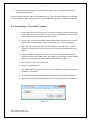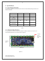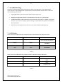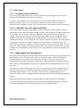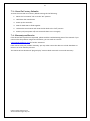
1
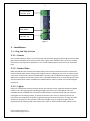
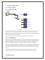
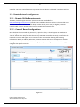
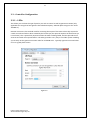
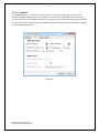
PIXLITE 16 USER MANUAL V1.2 1 Contents 1. - Safety Notes ...................................................................................................................................... 3 1.1 - Plug and Play Version.................................................................................................................. 3 1.1.1 - AC Power.............................................................................................................................. 3 1.1.2 - Opening Enclosure ............................................................................................................... 3 1.1.3 - Air Vents............................................................................................................................... 3 1.2 - Bare Board Version ..................................................................................................................... 3 1.2.1 - Providing Power ................................................................................................................... 3 2. - Installation ........................................................................................................................................ 4 2.1 – Plug and Play Version ................................................................................................................. 4 2.1.1 – Power .................................................................................................................................. 4 2.1.2 - Control Data ......................................................................................................................... 4 2.1.3 – Lights ................................................................................................................................... 4 2.2 - Bare Board Version ..................................................................................................................... 5 2.2.1 - Power and Links ................................................................................................................... 5 2.2.2 - Control Data ......................................................................................................................... 7 2.2.3 – Lights ................................................................................................................................... 8 3. – Network Configuration................................................................................................................. 9 3.1 – Physical Network ........................................................................................................................ 9 3.1.1 – Network Layout ................................................................................................................... 9 3.1.2 – IP Addressing ....................................................................................................................... 9 3.2 – Remote Network Configuration ............................................................................................... 10 3.2.1 - Remote Utility Requirements ............................................................................................ 10 3.2.2 – General Board Configuration ............................................................................................ 10 3.3 – Controller Configuration .......................................................................................................... 11 3.3.1 – LEDs ................................................................................................................................... 11 3.3.2 – Control............................................................................................................................... 12 3.3.3 – Advanced Configuration.................................................................................................... 13 3.3.4 – Network............................................................................................................................. 15 3.3.5 – Misc ................................................................................................................................... 15 4. – Operation ....................................................................................................................................... 16 4.1 – Startup...................................................................................................................................... 16 4.2 - Sending Data ............................................................................................................................. 16 PixLite 16 User Manual V1.2 © 2013 Advatek Lights Pty Ltd 2 5. - Firmware Upgrades......................................................................................................................... 16 5.1 - Physical Setup ........................................................................................................................... 16 5.2 - Obtaining New Firmware .......................................................................................................... 16 5.3 - Performing an Automatic Update............................................................................................. 16 5.4 - Performing a “Forced Boot” Update......................................................................................... 17 6. - Specifications .................................................................................................................................. 18 6.1 - Operating Specifications ........................................................................................................... 18 6.2 – Mechanical Specifications ........................................................................................................ 18 7. - Troubleshooting .............................................................................................................................. 19 7.1 - LED Codes.................................................................................................................................. 19 7.2 - Other Issues .............................................................................................................................. 20 7.2.1 - No Status/Power LEDs On.................................................................................................. 20 7.2.2 – Controller does not appear in utility ................................................................................. 20 7.2.3 - Light Outputs Not As Expected .......................................................................................... 20 7.3 – Reset To Factory Defaults ........................................................................................................ 21 7.4 - Warranty and Service................................................................................................................ 21 PixLite 16 User Manual V1.2 © 2013 Advatek Lights Pty Ltd 3 1. - Safety Notes 1.1 - Plug and Play Version 1.1.1 - AC Power Inside the fully assembled enclosure there are high voltage hazards. Extreme care must be taken if opening the enclosure as there are exposed high voltage terminals inside. Crimped fork terminals are used to connect the AC power input directly to the power supply. The US configuration uses a 110v/60Hz AC mains supply while the European/Australian configuration uses a 240V/50Hz AC mains supply. 1.1.2 - Opening Enclosure The enclosure can easily be opened by removing the 6 Phillips-head #2 screws located around the edge of the enclosure lid. The lid may be completely removed allowing full access to the circuit board, wiring and power supply inside. 1.1.3 - Air Vents The enclosure has two air vents located on the top end which allow the enclosure to equalize to a stable running temperature. It is critical to ensure these vents are not blocked or obstructed by anything while the controller is in operation. Anything restricting the flow of air out of the enclosure may cause it to overheat and could damage internal components. The unit features internal temperature regulation which ensures that the internal operating temperature will not rise above 78° centigrade. It is essential to operate the unit in a well ventilated area. 1.2 - Bare Board Version The board comes shipped in an anti-static bag and has several static-sensitive components on it. Appropriate anti-static measures should be observed when handling the board. 1.2.1 - Providing Power Power to the strings is applied via power bank screw terminal connectors J1 and J2, located on the left-hand edge of the board as shown in Figure 1 on the following page. They are both clearly marked on the PCB with the polarity and the power bank number. Logic power for the onboard circuitry may also be supplied to the board separately via the connector J3. Do not apply any power without first referring to section 2.2.1 for details on how to correctly configure the boards various power options. Outputs on channels 1-8 are powered via power bank 1 and outputs on channels 916 are powered via power bank 2. The voltage on each bank can be anywhere between 5V and 30V DC and it is the user’s responsibility to ensure that the power supply used matches the voltage of the pixel strings or strips they are using and that it can supply the correct amount of current. The total maximum current per power bank is 30 Amps, giving the board a total maximum current capacity of 60 Amps. PixLite 16 User Manual V1.2 © 2013 Advatek Lights Pty Ltd 4 J1 Power Bank 2 Channels 9-16 J3 Stand Alone Logic Power Input J2 Power Bank 1 Channels 1-8 Figure 1 2. - Installation 2.1 – Plug and Play Version 2.1.1 – Power The enclosure will have either a US or European style AC power plug exiting through the centre cable gland which should be connected to the AC mains supply. Care should be taken to ensure the plug connection is not exposed to dampness or rain if used outdoors when connected via an extension lead. 2.1.2 - Control Data DMX and LAN data are connected via cat5e cable to the internal PixLite 16 controller via the three external female RJ45 sockets exiting out through the centre cable gland. One is for an ethernet LAN connection and the other two are for DMX data in and out and are labelled accordingly. If using the DMX input in addition to ethernet, the last unit in the DMX network chain is recommended to have a 120 ohm termination resistor installed on its DMX output in order to prevent any unwanted signal reflections. 2.1.3 – Lights Lights are connected to the Plug and Play PixLite 16 controller via the 16 female waterproof pigtail sockets. There are eight pigtails protruding through each of the outer cable glands and each individual socket is labelled with a channel number between 1 and 16. Simply plug your Advatek pixel lights into the mating sockets, screw up the shroud covers and you are done. Ensure the connectors are screwed up all the way to guarantee proper internal connection. If using any cable extensions, plug these in-line with the socket and the light string. If using other lights then an appropriate 4 pin male plug will need to be used in order to mate with the female sockets on the PixLite 16 User Manual V1.2 © 2013 Advatek Lights Pty Ltd 5 enclosure (these are available on our webstore). The pin out of the enclosure female pigtail sockets is shown in Figure 2 below. Pin 1 ( +VE) Pin 4 (GND) Pin 3 (DATA) Pin 2 (CLK) Front View Figure 2 2.2 - Bare Board Version 2.2.1 - Power and Links The PixLite 16 has two split power banks with separate fuses. The board comes shipped from the factory with 3AG 30A fast blow fuses for fuse 1 and fuse 2. The split banks allow two different voltages to be used on the controller simultaneously. (You could run 5v lights off one bank and 12v lights off the other one for example.) Each individual channel output is also protected by a self-resetting polyfuse. These fuses are each rated to handle up to 5 amps of current at a room temperature of 25 °C. If blown, they will take several minutes to cool down and reset again once power is removed. Before connecting any power to the board, the power link options must be setup correctly to ensure safe and proper power operation. There are two main power configuration links L1 and L2 on the board, as shown below. L2 selects where the 5V VCC logic power for all the on-board logic circuitry is derived from. There are three main jumper configurations for this jumper link as follows: Configuration A: Logic power is derived directly from either the bank 1 or bank 2 power input. In order to use this configuration, the voltage being supplied to the corresponding power bank must be 5V DC +-10%. Exceeding 5V or reversing polarity for the VCC logic will destroy the on-board logic ICs as there is no protection. The L2 jumper should be in the 1-2 or ‘A’ position for this configuration as shown in figure 3 on the following page. PixLite 16 User Manual V1.2 © 2013 Advatek Lights Pty Ltd 6 A B C Figure 3 Configuration B: Logic power is derived from the on-board 5V regulator via one of the two main power banks. The regulator can accept any input voltage between 6V and 30V DC. This option is best used when powering either of the main power banks with a voltage greater than 5V DC. The L2 jumper should be in the 3-4 or ‘B’ position for this configuration as shown below: A B C Figure 4 Configuration C: Logic power is derived from the on-board regulator by a separate stand-alone power source via connector J3. The L2 jumper should be in the 5-6 or ‘C’ position for this configuration as shown below: A B C Figure 5 L1 jumper function is simply to select which of the two power banks (B1 or B2) will be used to supply either the 5V VCC logic or on-board regulator input when either configuration A or B (above) is used for L2. The 1-2 position selects power bank 1 and 2-3 position selects power bank 2. PixLite 16 User Manual V1.2 © 2013 Advatek Lights Pty Ltd 7 L2 VCC Power Jumper L1 Logic Power Bank Select Jumper Figure 6 All PixLite 16 boards are shipped with the jumpers set for the ‘B’ configuration and for VCC power via bank 1 by default. 2.2.2 - Control Data Control data to the PixLite 16 is achieved via the on-board LAN and DMX connectors. The LAN is connected via the single horizontal ethernet jack J9. DMX is connected via two vertical RJ45 sockets J7 and J8, as well as a horizontal screw terminal J6. All these connectors are located on the far righthand side of the board as shown in figure 7 below: J6 DMX IN/OUT J8 DMX IN J7 DMX OUT J9 Ethernet Jack Figure 7 PixLite 16 User Manual V1.2 © 2013 Advatek Lights Pty Ltd 8 The hardware layer on which the DMX 512 protocol operates is the RS485 electrical communications standard. This is a differential transmission system consisting of a two wire differential twisted pair and single wire ground connection. The +ve signal is commonly referred to as ‘A’ while the –ve signal is referred to as ‘B’. The A, B and ground connections are clearly labelled on the PCB for the DMX screw terminal J6. The data pin-out for the two RJ45 sockets J7 and J8 is shown in figure 8 on the following page. Figure 8 2.2.3 – Lights Lights are connected to the bare board version directly via the pluggable screw terminal connectors along the top and bottom edges of the board. Each connector is labelled with its string or channel number and pin 1 is also clearly marked. There is also a pin out for the connectors clearly marked on the PCB silk screen underneath the power LED for quick reference. Simply screw your light strings into each screw terminal plug and then plug them into the mating sockets. The pin out for the connectors is also shown in Figure 9 below. +VE | CLK |DATA| GND Pin 1|Pin 2|Pin 3 | Pin4 4GND Figure 9 PixLite 16 User Manual V1.2 © 2013 Advatek Lights Pty Ltd 9 3. – Network Configuration 3.1 – Physical Network 3.1.1 – Network Layout Server/Host Machine PixLite 16 Router Switch PixLite 16 PixLite 16 PixLite 16 PixLite 16 Figure 10 Figure 10 shows a typical network topology for the PixLite 16 controller(s) LAN. The host machine should connect to a router and then to the PixLite 16 controller(s). If you are only using a few controllers, they can be connected straight to the router. Larger installations will require a network switch between the router and controllers. The PixLite 16 controller(s) can also be integrated straight into any pre-existing LAN. 3.1.2 – IP Addressing DHCP is always enabled by default so the controller can immediately work on any existing network with a router. However it is recommended that you assign a static IP address once communications have been established via the utility. If in DHCP mode and the controller is not assigned an IP by a DHCP server, it will then timeout after 15 seconds and default to a static IP of 192.168.0.50 If DHCP mode is enabled both LEDs will flash together until the controller receives an IP address, at which point the power LED will remain on solid and the status LED will flash slowly indicating it is in run mode and ready for use. If a static IP address is assigned, then the power LED will be solid from power up. In the event that a controller needs to be forced to its default IP, a simple procedure can be employed on power up. This requires holding down the reset button before powering up the PixLite 16 User Manual V1.2 © 2013 Advatek Lights Pty Ltd 10 controller. Once the controller powers up release the reset button. The board’s IP address will now be 192.168.0.50 3.2 – Remote Network Configuration 3.2.1 - Remote Utility Requirements The utility “Adavtek Lights Assistant” (the latest version is available from www.advateklights.com/resources) needs to be installed on the host machine. The controller must then be connected to the PC network adapter either directly via a cat5e (or higher) crossover network cable, or via a network router using a straight-thru network cable. 3.2.2 – General Board Configuration Once the board is connected and powered on, open the utility. It should appear in a window as shown in figure 11 below. By default it should open on the “Network Devices” tab. Next, click on the “Search” button. The utility will then discover any PixLite 16 controllers currently connected to the LAN. Each controller will appear on its own row in the main window showing the following information: Model, IP Address, Nickname, Firmware Version and Current Temperature. Double clicking on a controller in the list will then bring up a separate configuration window allowing you to configure that specific controller. Figure 11 PixLite 16 User Manual V1.2 © 2013 Advatek Lights Pty Ltd 11 3.3 – Controller Configuration 3.3.1 – LEDs This allows you to select the type of pixel IC you wish to control as well as gamma correction (only applicable for strings that have greater than 8 bit data capacity. Advatek pixel strings use the 12 bit TLS3001 IC.) Gamma correction is the method used for correcting the output of the LEDs so that they respond in a much more linear fashion when viewed by the human eye (the spectral response of the human eye is non-linear). This is particularly important when the LEDs are being faded, and also provides more accurate and vivid color representation. The utility provides a very easy to use slider system enabling you to easily set the gamma correction value for each RGB color. Typically a gamma-corrected value of 2.0 is a good place to start. Figure 12 PixLite 16 User Manual V1.2 © 2013 Advatek Lights Pty Ltd 12 3.3.2 – Control This window allows you to specify the start universe, start channel, nodes per string, ethernet protocol and DMX mixing function. For the PixLite 16 controller, this will default to the values of 1 for start universe and start address, 50 nodes per string (for use with Advatek pixel strings) and sACN for the protocol. (The Artnet protocol and DMX mixing are currently grayed out and will be available in future software upgrades.) Figure 13 PixLite 16 User Manual V1.2 © 2013 Advatek Lights Pty Ltd 13 3.3.3 – Advanced Configuration This allows for advanced configuration of the 16 pixel strings/strips. Each string can be individually configured for its start universe, start channel, number of nodes (or pixels), null pixels, zig-zag and reversing. By using combinations of these options it can make setting up your pixel strings or strips more practical and simple, and often also results in shorter sequencing times. Figure 14 PixLite 16 User Manual V1.2 © 2013 Advatek Lights Pty Ltd 14 Null Pixels Null pixels allow the controller to ignore or skip a specified number of pixels in a given string or strip. This is useful when you want to extend your string, as the data signals in pixel strings and strips are not designed to travel over long distances. Each pixel has its own IC which actually re-transmits the entire data signal. By inserting some “null” pixels into a given length of cable before you get to the start of the actual string, it will reproduce the digital signal allowing it to reach the start of the actual string (with the null pixels being skipped). Note that this is not necessary when using heavy duty Advatek pixel string extension leads; they are already capable of extending the length of a given string by up to 15m (45’). The other use for null pixels is for when you may not want to use the entire string. In this case you can simply tell the controller to ignore or skip the pixels you don’t need. ZigZag This feature allows pixel addresses to be allocated in a more logical order in the sequencer. For example, you might have a megatree consisting of 16 strings of 50 pixels in your display. Starting at the first string, you would string pixels 1-50 from bottom to top, and then pixels 51-100 from top to bottom in the 2nd string and so on, zig-zagging up and down all the way around. When finished, if you turned the pixels on in order from the lowest address to the highest, you would see a pattern that started at the bottom of the first string and zig-zagged up and down as you move around the megatree. When programming the pixels in the sequencer however, it’s much easier if the pixels light in a more intuitive order. In our example, we would use the zigzag feature to tell the controller that the pixels reverse direction every 50 pixels. Thus lighting sequential pixels now produces the desired effect, the first string lights from bottom to top, then the 2nd string from bottom to top, etc. Reversing Turning on the reversed option tells the controller to light that string or strip backwards. This means the first pixel to light will actually be the last pixel in the string instead of the first pixel in the string. This is very useful when pixels are used to outline a roofline and the start of the strings or strips is at the mid-point, with one running off to the right and the other to the left. Usually such an arrangement would result in the first string lighting from the middle and moving to the far right before then returning to the middle and then starting down the left string moving to the far left. With the reverse option enabled on the first string going to the right, you could address the pixels sequentially in the sequencer and the pixels would start from the far right and move sequentially through the middle and across to the far left. PixLite 16 User Manual V1.2 © 2013 Advatek Lights Pty Ltd 15 3.3.4 – Network Here you can specify the static IP address and subnet mask that the controller will operate on as well as the type of IP connection. Figure 15 3.3.5 – Misc This allows you assign a custom nickname to the controller, perform a firmware update and also displays the current bank voltage of each of the two main power banks. Figure 16 PixLite 16 User Manual V1.2 © 2013 Advatek Lights Pty Ltd 16 4. – Operation 4.1 – Startup Upon applying power, if you already have strings connected they will flash very briefly (<50mS) and then immediately turn off as the controller takes control of the pixels. If no data is being piped through to the controller then the pixels will remain turned off until valid data is received. During normal operation the green power LED will remain on solid and the status LED will flash slowly to indicate the controller is connected to a valid network and is ready to process data. 4.2 - Sending Data Data is sent from the host machine to the controller via the LAN using a “DMX over IP” protocol such as sACN (E1.31) or Artnet. Data may also be sent from a separate source over a standard DMX512 network in certain applications. This can be set-up with a PC using a USB to DMX512 (RS485) adaptor or using any other standalone type of DMX controller.(If using an RS485 adapter, ensure it has its USB drivers correctly installed or it will not appear in either the configuration utility or the lighting software program.) 5. - Firmware Upgrades The controller is capable of having its firmware upgraded (new software). An upgrade is typically performed to fix any bugs that may have been overlooked in previous revisions or to add new features. 5.1 - Physical Setup To perform a firmware upgrade, ensure that you have your PixLite 16 controller connected to the LAN network as per section 3.1.1. 5.2 - Obtaining New Firmware The latest firmware is available from the Advatek Lights website at the following link: http://www.advateklights.com/resources It will come in a “.hex” format. 5.3 - Performing an Automatic Update 1. Open the config utility. Click “Search” and once the desired controller appears in the main window, double click on it. 2. A configuration window will appear. Click on the “Misc” tab and then locate the “Upgrade Firmware” button and click on it. A “firmware update” window will appear (as shown in Figure 17). Click “browse” to locate the firmware file you wish to download. 3. Click on the “update” button. 4. Once the download is complete, a message box will pop up saying it has completed successfully. PixLite 16 User Manual V1.2 © 2013 Advatek Lights Pty Ltd 17 5. The controller will automatically reboot itself and then start running the new firmware application immediately. If there is something wrong with the upgraded firmware, repeat the process again if it is still visible in the configuration utility. Otherwise, refer to the troubleshooting section for further information. 5.4 - Performing a “Forced Boot” Update 1. Power down the controller. Move the “Force Boot” jumper L5 (located centre-right on the board) into the “On” position. (If you have a “Plug and Play” version, the lid of the enclosure will need to be removed to do this.) 2. Apply power, the status and power LEDs should be flashing alternately to indicate the controller is in bootloader mode. It is now ready for a firmware upgrade. 3. The current bootloader will default to an IP address of 192.168.0.50 in the force mode so you must ensure you are running it on a network compatible with this IP address. 4. Using the Advatek Configuration utility, click search in the main window and you should see the controller appear with “bootloader” in the firmware column. Double clicking on it will bring up the file browse window as shown in figure 17. 5. Click browse to locate the firmware file. 6. Click on the update button. 7. The update will only take about 5 seconds, and a message box will pop up once the download is completed. 8. Power the board down again and move the jumper L5 back to the “Off” position. 9. Apply power again and the board should now be operating with the new firmware. Figure 17 PixLite 16 User Manual V1.2 © 2013 Advatek Lights Pty Ltd 18 6. - Specifications 6.1 - Operating Specifications The table below specifies maximum parameters and the recommended operating conditions for a PixLite 16 controller. PARAMETER VALUE/RANGE UNITS TOLERANCE Logic Input 5 V DC +/-10% Power Bank Input Volta Per Max Capacity 5-30 V DC +/-5% 30 A +/-5% Power Bank Logic Current Consumption (@ 5V) DC) Operating 60 mA +/-10% -20 to +80 °C +/-5% Temperature Polyfuse Max @25°C 5 A +/-10% Table 1 6.2 – Mechanical Specifications The “Plug and Play” enclosure has dimensions 185mm x 160mm x 130mm or 7.4” x 6.4” x 5.2”. The bare board dimensions are as shown below in figure 18. 4 x 3mm (0.12”) Mounting Holes 120mmm (4.8”) 200mm (8”) Mounting Holes Figure 18 PixLite 16 User Manual V1.2 © 2013 Advatek Lights Pty Ltd 19 7. - Troubleshooting Generally, troubleshooting requires looking at the LEDs on the controller. In the plug and play version there is a high voltage power supply inside so extreme caution must be taken. In this case, use the following procedure: Unplug the power from the controller before removing the case Apply power again once the lid is removed and the controller is in a safe position DO NOT TOUCH the inside components of the controller while power is applied, only look at the LEDs. If you want to change a jumper setting or a power bank fuse, power should always be removed first. Power down and reattach the lid as soon as you have finished troubleshooting. 7.1 - LED Codes Please refer to the table below for condition codes for the onboard status and power LEDs. POWER LED (GREEN) STATUS LED (RED) CONDITION SOLID SLOW FLASHING SOLID SOLID NORMAL OPERATION, MAIN APPLICATION RUNNING OK MAIN APPLICATION NOT RUNNING ALTERNATE FLASHING ALTERNATE FLASHING BOOTLOADER MODE OFF OFF NO POWER Table 2 Please refer to the table below for condition codes for the ethernet jack status LEDs. LINK LED (GREEN) DATA LED (YELLOW) CONDITION SOLID RAPID FLASHING SOLID OFF OFF OFF CONNECTED OK, RECEIVING DATA CONNECTED OK, NO DATA DATA NO LINK ESTABLISHED OR POWER IS OFF Table 3 PixLite 16 User Manual V1.2 © 2013 Advatek Lights Pty Ltd 20 7.2 - Other Issues 7.2.1 - No Status/Power LEDs On If you have a plug and play controller, ensure that the outlet you are plugged into is active. If so, check that the main power bank fuses have not blown. If you have a bare board version and you have set up your own power supply, ensure that it is supplying voltage correctly. If it is, ensure that the jumpers are set to the correct settings as described in the “Installation” section. If they are still correct, ensure that the fuses have not blown. 7.2.2 – Controller does not appear in utility Firstly check that the network is setup properly. The host machine’s network adapter is typically connected to a router and then possibly through a switch to the controller via straight through cat5e or cat6 cables. If the controller is setup to use DHCP then ensure that the router has “DHCP” enabled. Check the status LEDs on the Ethernet jack as per table 3. A green LED indicates a valid 100M/bit connection and a flashing yellow LED indicates data activity on the network. If you are confident the network is setup properly but the controller still does not appear in the utility window, try forcing the controller to its default IP address as found in section 3.1.2 and then “ping” the controller’s IP from the host machine. If this still fails, there is still an issue with the router, switch (if used), your network adapter, the physical network cable or the PixLite 16 controller itself. Try using another router and a different network cable or even using a different host machine altogether as a last resort. 7.2.3 - Light Outputs Not As Expected If the lights are not turning on at all then double check all power connections, string connections and main bank fuses. There are two main fuses (one for each power bank) as well as the individual thermal polyfuses on each channel. If the polyfuse is very warm or hot to the touch on the corresponding channel that the lights do not work on, it is likely that the fuse has blown internally due to a short circuit somewhere in the string or strip (it will reset itself automatically once it cools down again.) If the lights turn on but are displaying colors you are not expecting, ensure the string(s) itself is not faulty by comparing to other known working strings if possible. Then verify the controller can be discovered using the utility. If it can’t be, refer to 7.2.2 for further troubleshooting tips. If it is discoverable, then ensure the string(s) has been programmed correctly in the actual lighting control software. Failing that, check the status LEDs for more information and refer to section 7.1 “LED Codes”. If there is no fault indicated by the LEDs and you are not using a plug and play version, check that your wiring of the lights is in accordance with section 2.2.3 “Installing the Lights”. PixLite 16 User Manual V1.2 © 2013 Advatek Lights Pty Ltd 21 7.3 – Reset To Factory Defaults To reset the controller to its factory default settings do the following: 1. Move the “Force Boot” link L5 to the “On” position. 2. Hold down the reset button 3. Power up the controller 4. Wait for both LEDs to flash together 5. Release the reset button and move the link back to the “Off” position 6. Power cycle (turn power off, wait 5 seconds then turn it on again) 7.4 - Warranty and Service If the device fails to perform as expected, please read the troubleshooting area of this manual. If you cannot solve the problem using that information, you can send an e-mail to [email protected] for further assistance. If we cannot solve your problem remotely, you may either return the device to a local distributor or return it to us for warranty services. The PixLite 16 bare board and “plug and play” versions both come with a 12 month warranty. PixLite 16 User Manual V1.2 © 2013 Advatek Lights Pty Ltd