1
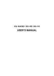
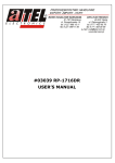
Longshine Technologie Europe GmbH
www.longshine.de
FCC Certifications
This Equipment has been tested and found to comply with the limits for a
Class A digital device, pursuant to part 15 of the FCC Rules. These limits
are designed to provide reasonable protection against harmful interference
when the equipment is operated in a commercial environment. This
equipment generates, uses, and can radiate radio frequency energy and, if
not installed and used in accordance with the instruction manual, may
cause harmful interference to radio communications.
Operation of this equipment in a residential area is likely to cause harmful
interference in which case the user will be required to correct the
interference at his own expense.
This device complies with Part 15 of the FCC Rules. Operation is subject to
the following two conditions: (1) this device may not cause harmful
interference, and (2) this device must accept any interference received;
including interference that may cause undesired operation.
CE Mark Warning
This equipment complies with the requirements relating to electromagnetic
compatibility, EN 55022 class A for ITE, the essential protection
requirement of Council Directive 89/336/EEC on the approximation of the
laws of the Member States relating to electromagnetic compatibility.
Company has an on-going policy of upgrading its products and it may be
possible that information in this document is not up-to-date. Please check
with your local distributors for the latest information. No part of this
document can be copied or reproduced in any form without written
consent from the company.
Trademarks:
All trade names and trademarks are the properties of their respective
companies.
Copyright © 2003, All Rights Reserved.
Document Version: 2.0
Table of Contents
Unpacking Information ................................................... 1
Introduction to 100/1000Mbps Ethernet Switch .......... 2
General Description ................................................... 2
Key Features................................................................ 3
The Front Panel........................................................... 4
LEDs Definition .................................................. 4
The Rear Panel ............................................................ 6
Power Receptacle................................................ 6
Installation of 100/1000Mbps Ethernet Switch............ 7
Desktop Installation ................................................... 7
Station connection .............................................. 8
Switch connection............................................... 8
Rack-mount Installation ............................................ 8
Backbone Network Application............................... 9
Jumbo frame........................................................ 9
Product Specifications.................................................... 10
Unpacking Information
Thank you for purchasing the 100/1000Mbps Ethernet Switch.
Before you start, please check all the contents of this package.
The product package should include the following:
1.
2.
3.
4.
5.
One Gigabit Ethernet Switch
One power cord
Rubber foot and screws
Rack-mount brackets (for 19”model)
User’s Manual
1
Introduction to 100/1000Mbps Ethernet Switch
General Description
The device is a 100/1000Mbps Ethernet Switch.
Compare to the traditional 10/100Mbps Ethernet, the switch
delivers a dedicated Gigabit connection to every attached
client with no congestion issue. The gigabit ports also provide
the fat pipe to the server or backbone connectivity for boosting
the total system performance. Moreover, the NWay
auto-negotiation operation automatically negotiates with the
connected partners on the network speed and duplex mode;
that provides an easy way to integrate 10/100/1000Mbps
networks with no pain. It is ideal for micro-segmenting large
networks into smaller, connected subnets for improved
performance, enabling the bandwidth demanding multimedia
and imaging applications.
Store-and-forward switching mode promises the low latency
plus eliminates all the network errors, including runt and CRC
error packets. To work under full-duplex mode, transmission
and reception of the frames can occur simultaneously without
causing collisions as well as double the network bandwidth.
The switch is plug-n-play without any software to
configure and also fully compliant with all kinds of network
protocols. Moreover, the rich diagnostic LEDs on the
front-panel provide the operating status of individual port and
whole system.
2
Key Features
Complies with 10BASE-T specifications of the IEEE802.3 standard
Complies with 100BASE-TX specifications of the IEEE802.3u standard
Complies with 1000BASE-T specifications of the IEEE802.3ab standard
16/24 * 10/100/1000Mbps RJ-45 Nway ports
Supports NWay protocol for speed (10/100/1000Mbps) and duplex
mode (Half/Full) auto-detection
Supports MDI/MDI-X auto crossover
Supports full and half duplex operation on all ports
Supports back-pressure (half duplex) and flow control (IEEE 802.3x)
Wire-speed packet filtering and forwarding rate
Store-and-forward architecture filters fragment & CRC error packets
Supports 4K(16-port)/8K(24-port) MAC address entries in whole
system
272K(16-port)/400K(24-port) Bytes buffer memory
Support up to 9K bytes jumbo Frames (24-port only)
Supports extensive LED indicators for network diagnostics
13”/19” rack mountable
Internal power adapter
FCC Class A, CE
3
The Front Panel
The front panel of the switch is shown as below
Please refer to the following table for LED definition
13-inch Model (16-port)
13-inch Model (24-port)
19-inch Model (16-port)
19-inch Model (24-port)
LEDs Definition
The rich diagnostic LEDs on the front panel can provide the
operating status of individual port and whole system.
Power LED
This indicator lights green when the switch is receiving power;
otherwise, it is off.
LED
Power
Status
Steady Green
Off
4
Operation
Power is on
Power is off
Port LEDs
Port LEDs indicators locate on the front panel for showing the
operating status of 10/100/1000Mbps Ethernet switching ports.
Speed LED
10Mbps: The 10/100M LEDs will show steady amber. The
LEDs will blink amber while data receiving or
transmitting.
100Mbps: The 10/100M LEDs will show steady green. The
LEDs will blink green while data receiving or
transmitting.
1000Mbps: The 1000M LEDs will show steady green. The
LEDs will blink green while data receiving or
transmitting.
LED
Status
Steady /Blinking Amber
10/100M
Steady/Blinking green
1000M Steady/Blinking green
5
Operation
Connected as 10Mbps/Active
Connected as 100Mbps/Active
Connected as 1000Mbps/Active
The Rear Panel
The rear panel of the switch is shown as below
13-inch Model (16-port)
13-inch Model (24-port)
19-inch Model (16-port)
19-inch Model (24-port)
Power Receptacle
For compatibility with electric service in most areas of the
world, the switch’s power supply automatically adjusts to
line power in the range (100~240VAC, 50/60Hz).
Plug the female end of the power cord firmly into the
receptacle on the rear panel of the switch. Plug the other
end of the power cord into an electric service outlet then
the power will be ready.
6
Installation of 100/1000Mbps Ethernet Switch
This switch can be placed directly on your desktop, or mounted in a
rack. After completing the device installation, and you can
immediately use the switch simply by attaching the cables and
turning the power on.
Desktop Installation
For desktop installation, the switch needs to put on a clean, flat desk
or table close to a power outlet. Plug in all network cables and the
power cord, then the system is ready.
Before installing the switch, you must ensure:
1.
2.
3.
4.
It is accessible and cables can be connected easily
Cabling is away from:
*Sources of electrical noise such as radios, transmitters and
broadband amplifiers
*Power lines and fluorescent lighting fixtures.
Keep water or moisture off
Airflow around the unit and through the vents in the side of
the case is great for heat radiation (company recommends
that you provide a minimum of 25 mm clearance)
To prolong the operational life of your units:
1.
2.
3.
Never stack unit more than eight sets high if freestanding
Do not place objects on top of any unit or stack
Do not obstruct any vents at the sides of the case
7
Station connection
Connect each station to the switch by twisted-pair cable. Plug one
RJ-45 connector into a RJ-45 port of the switch, and plug the other
RJ-45 connector into the station’s network adapter. Power on the
switch and then system is ready.
Switch connection
In making a switch interconnection, you could use any port to
connect another switch with straight or crossover cable. As all the
ports support auto MDI / MDI-X function, using a straight cable
to make a switch-to-switch connection is allowed.
For cable selection, refer to the following table:
Media
Speed
Wiring
10Mbps Category 3,4,5 UTP/STP
10/100/1000Mbps copper 100Mbps Category 5 UTP/STP
1000Mbps Category 5,5e UTP/STP
Rack-mount Installation
The 19” model may standalone, or may be mounted in a standard
19-inch equipment rack. Rack mounting produces an orderly
installation when you have a number of related network devices.
The switch is supplied with rack mounting brackets and screws.
These are used for rack mounting the unit.
Rack Mounting the Switch in the 19-inch rack:
1.
2.
3.
4.
5.
Disconnect all cables from the switch before continuing.
Place the unit the right way up on a hard, flat surface with
the front facing toward you.
Locate a mounting bracket over the mounting holes on one
side of the unit.
Insert the screws and fully tighten with a suitable
screwdriver.
Repeat the two previous steps for the other side of the unit.
8
6.
7.
Insert the unit into the 19" rack and secure with suitable
screws (not provided).
Reconnect all cables.
Backbone Network Application
This page provides a sample of network topology as a
high-bandwidth backbone. For upgrading the 100Mbps network,
it’s the ideal choice.
You can connect the switch with existing switches, hubs, and any
PCs or servers with 1000Mbps NIC.
Jumbo frame (For 24-port Model)
The 24-port model provides 9K jumbo frames, which means the
frames size is larger than normal 1.5K. With the Jumbo frame
function, you can get better network performance, because the
switch can send more data at the same time with lower CPU
usage.
9
Product Specifications
Standard
Interface
Cable
Connections
Network Data
Rate
Transmission
Mode
LED
indications
Memory
Jumbo frame
Emission
Operating
Temperature
Operating
Humidity
Power Supply
16Port
24Port
IEEE802.3 10BASE-T
IEEE802.3u 100BASE-TX
IEEE802.3x full-duplex operation
IEEE802.3ab 1000BASE-T
16 * 10/100/1000Mbps 24 * 10/100/1000Mbps
auto MDI/MDI-X
auto MDI/MDI-X
RJ-45 switching ports
RJ-45 switching ports
RJ-45 (10BASE-T): Category 3,4,5 UTP/STP
RJ-45 (100BASE-TX): Category 5 UTP/STP
RJ-45 (1000BASE-T): Category 5,5e or enhanced
UTP/STP
10/100/1000Mbps Auto-negotiation
10/100Mbps Full-duplex, Half-duplex
1000Mbps Full-duplex
System
Power
RJ-45 Port
10/100M; 1000M link/act
4K MAC entries
8K MAC entries
272K Buffer Memory
400K Buffer Memory
N/A
9K bytes
FCC Class A, CE
00 ~ 500C (320 ~ 1220F)
10% - 90%
Internal power supply
Internal power supply
5V 8A
5V 10A
100-240V/ 50-60Hz
100-240V/ 50-60Hz
61NB-70240-200
10