1
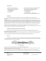
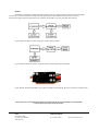
OPTICAL KILL SWITCH
For RC model GAS engines electronic ignition.
USER MANUAL
Description
Optical Kill Switch was designed specifically for large RC models powered by gasoline engines with electronic spark
ignition. Its main task is to give the possibility to shutdown the gas engine from RC Transmitter and also to separate receiver circuits
with RC accessories from the circuit powering the ignition unit, which may cause strong electromagnetic noise, and as a result loss
of control.
Optical Kill Switch considerably reduces the possibility of RC range loss. Simultaneously, giving the possibility to emergency turn off
the engine in a few ways.
The unit is equipped with additional functions which aditionaly increases safety during practicing this
wonderful hobby:
- Double opto-isolated transmission controlling ignition unit (ON/OFF)
Total resistance to electromagnetic interference induced in the ignition by separating circuits by two optocouplers
- Switching ON and OFF the ignition directly from RC transmitter
Applied to switch off the engine also in case of throttle servo failure
- Ignition switching sequence protection
When the ignition cutoff switch at TX is in “ON” position during preparation and powering up the model, the
ignition WON’T TURN ON! This prevents unexpected starting the engine. In order to turn on the ignition you
must at first place TX cutoff switch into the OFF position and then “ON” (operating similar as in the electric
motors controllers)
- High quality wires
Receiver, ignition and battery connection wires are all high quality 22AWG gauge.
- Fail-Safe function
Possible to setup a Fail-Safe function. In case of the communication lack with model for longer than 1 second
the kill switch will turn off the engine and the LED diode will blink from now on, until reset.
- Wide range of power supply voltage
OPTICAL KILL SWITCH works correctly with 3.0 – 24.0 V on the RC receiver side, and 3.0 – 20.0 V on the ignition battery
side. Maximum current consumption allowed is 5.0 A constant and 16.0 A temporarily.
- No need to use additional mechanical switch
Battery drain current when device is OFF is ONLY! 1,8uA (micro Ampere) at 6,0 V battery. And 20,0 uA at 16,V. It
means that 2000mAh, 6V battery will drain out to zero for 126 years! 1,8uA drain current is much less than
battery self discharge ratio.
- LED indicating the operating status
Clearly visible diode indicates whether the ignition unit is turned off or on. Additionally the LED performs an
important signaling role in case of stopping the engine by interference and transition into the Fail-Safe mode, or
problems with the electrical installation. During disruption for longer than 1 second, the device is switched into the third
operating status (Fail-Safe) causing switching the engine off and start blinking of diode. Diode will still blink also after the
end of disruption. That means also after landing. In this way LED informs from what reasons the engine stopped in the air.
Change of TX cutoff switch position also doesn’t erase the error of blinking diode. In order to reset Fail-Safe signaling
(blinking) you must turn off and again turn on the receiver power with the main power switch.
Engine will be shut down in the case of:
- Range loss for longer than 1 second (LED blinks). Less than 1 sec. will not perform any action
- Faulty power supply of the RC receiver (breaks with the power supply or its lack)
-Turning OFF the engine by using TX system
SETLO
os. Przyjaźni 13/80
61-687 Poznań, POLAND
www.setlo.com
Technical support:
Tel.: +48 535 792 010
e-mail: [email protected]
Technical data
- dimensions: 35mm x 18mm x 5mm
- RX plug: Futaba female, 22AWG, 300mm
- power supply from Rx: 3,0V – 24,0V
1 - 7 x (LiPo/Li-Ion/LiFe)
3 - 20 x (NiMh/NiCd)
- weight: 15,0 gram
- power supply ign. bat.: Futaba / JR male 22AWG, 150mm
- ignition plug: Futaba / JR female 22AWG, 150mm
- LED wire: 300mm, diode (fi)3mm ultra bright
- ign. power supply: 3,0V – 20,0V
1 - 7 x (LiPo/Li-Ion/LiFe)
3 - 16 x (NiMh/NiCd)
- max current: 5A continous, 16A temporarily
- current drain when OFF: 1,8uA at 6,0V; 20,0uA at 16,0V
Installation
Device must be installed inside the fuselage. Wire connector with the RCVR description is plugged in the RC
receivers free proportional channel. Although the device is resistant to vibrations, but if possible you must install them on elastic
foam plate.
By default Ignition circuit is powered from the ignition battery (output with the BAT description). Voltage stabilizer (if needed)
should be applied if the level of battery volage is higher than acceptable input voltages for ignition unit . Stabilizer can be installed
both before as well as behind the Optical Kill Switch. (putting it at the output – betweend ignition module and kill switch eliminates
need of using mechanical switch) Ignition unit is connected to the output with IGN description and it is powered directly from it.
Signaling LED diode must be installed in the the visible place, it provides useful information about operating status of kill switch.
Because the main task of Optical Kill Switch is electric separation of the RC receiver circuits from ignition circuits, should
make every effort so that remaining wires of these circuits won’t mix with each other and were possible as farthest from each other.
The only element connective both circuits should be the Optical Kill Switch.
Possiblity to power ignition module from receiver battery.
By default the device is using power from receiver for system logic and from independent battery to power the
ignition module. Those circuits are double opto-isolated from each other. However it is possible to power the ignition module also
from receiver, without using extra battery.
To do so it it necessarily to remove heat shrink tube and solder together two pairs of pads (bottom side under the BAT and IGN
wires, mrked as [B] and [C] at the end of this manual). From now the battery input wire is not being used.
First run
During first run it is necessary to carry out the calibration of channel in which the Optical Kill Switch is plugged, analogy
like during the regulation of servomechanism end points. The Kill Switch recognizes 3 levels of the input signal from the RC receiver,
corresponding to 3 operation status (see Figure below).
Calibration procedure along with adjusting of Fail-Safe level should proceed as follows:
Set the value of signal on the RC receiver channel in which Kill Switch is plugged on value in which the device operates in the FailSafe mode (diode will start to blink – short red impulses).
Program the transmitter / receiver so that this value will be generated during the break of connection in the Fail-Safe mode
(procedure of programming the receiver in F/S is different for all sort of transmitters producers, we recommend to look into the
SETLO
os. Przyjaźni 13/80
61-687 Poznań, POLAND
www.setlo.com
Technical support:
Tel.: +48 535 792 010
e-mail: [email protected]
instruction or to get in touch with the radio dealer).
Next step is to reduce signal value by setting the EPA (End Point Adjustment) in RC transmitter to such values that the kill switch can
switch only between the value TURN ON and TURN OFF. For all sort of apparatus producers these values may slightly differ. Value of
switch from ON to OFF position has hysteresis, which protects against appearance of the uncertain state.
Principles of operation and modes
The Optical Kill Switch has a few modes:
-Switching sequence protection – if during startup the RC transmitter and power switch in the model (both the RC receiver and
ignition system witch at TX) switch on the RC TX, responsible for turning on the Kill Switch, is the ON position. Ignition will
NOT! be turned on. This protection is similar to electric model engines which secure during the adjusted of high throttle
and doesn’t start the engine during power model switch. In order to start the ignition must at first set the TX ignition
switch lever into the OFF position and then into the ON position. It is aware switching the ignition by mistake or when user
is not ready for it.
-LED Diode signaling the operation status – four states of the diode are possible.
– Diode is TURNED OFF, when the ignitions is switched off by the user through the lever switch cutoff on TX and there was
no problems with the radio transmittion.
– Diode is TURNED ON CONTINUOUSLY, when the ignitions was switched on by the user through the lever switch on RC TX
and were no problems with the radio transmittion.
– Diode BLINKS SHORT IMPULSES, when the ignition was switched off by break occurrence in communication between the
model and RC transmitter for longer than 1 second. If connection will return the diode will turn into:
– BLINKS LONG IMPULSES state, the ignition is switched on again due to the position of lever switch cutoff on RC TX;
however the blink signal indicates that there was a problem with the connection during flight. While disruption the engine
will be turned off; however for large models equipped with the on board starter it is
possible to restart engine during flight. Disruptions signal (diode BLINKS) reset is possible to only by manually
restarting on power switch for RC receiver.
-Problems with power supply of the RC receiver – if such a problem will appear and modeler won’t be able to control the model
flight by lack of receiver and serve power. Also the Optical Kill Switch will turn off the engine.
-Pre-Flight range test - Blinking diode signal of the Fail-Safe can be used to maintain a range test before the flight. For that purpose
must: Turn on the RC TX, turn on the power of model. At TX ignition lever switch position in the position TURNED OFF
must move away with TX to the appropriate distance. After return to the model check the status of LED. If diode BLINKS
it means that the receiver turned into the Fail-Safe mode during moving away with the transmitter. If diode doesn’t blink it
means that there was no problem with the connection during the test.
NOTE!!!
If RC transmitter that you have doesn’t have the possibility to program the Fail-Safe mode you must omit this stage of
programming the transmitter and confine to set up EPA value of the given channel in order to be able turn Kill Switch on and off by
cutoff, without going into the blinking diode state. The LED diode then won't inform about the lack of connection with model and
will not turn off the engine in this case.
Also If Your radio have Fail-Safe option but You dont want to use a blinking diode signalisation You can:
- Disabling the LED blinking F-S indication - This function can be disabled by soldering pair of pads (bottom side under the
RCVR wires marked as [A] at the end of this manual). From now there will be only active ON and OFF function (see figure
below).
SETLO
os. Przyjaźni 13/80
61-687 Poznań, POLAND
www.setlo.com
Technical support:
Tel.: +48 535 792 010
e-mail: [email protected]
NOTE!!!
Remember that application of Opticall Kill Switch doesn’t justify the implementation of careless electrical installation.
All wires and connections should be carefully made and appropriately secured. Additional safety increase is a task of
kill switch during practicing this hobby, rather than avoiding or eliminating errors of the assembly other elements.
Figure. Using extra battery to power the ignition module. Defaut aplication.
Figure. Using one battery for receiver and ignition module. Solder [B] and [C] pads together.
Figure. Bottom side of Optial Kill Switch. [A]- pads for disabling F-S blinking diode. [B] and [C] - pads for one battery setup
Thank you for the trust and purchase of devices. Simultaneously we wish successful flights and unforgettable
moments while piloting your wonderful models.
SETLO
os. Przyjaźni 13/80
61-687 Poznań, POLAND
www.setlo.com
Technical support:
Tel.: +48 535 792 010
e-mail: [email protected]