1
instruction or to get in touch with the radio dealer).
Next step is to reduce signal value by setting the EPA (End Point Adjustment) in RC transmitter to such values that the kill switch can
switch only between the value TURN ON and TURN OFF. For all sort of apparatus producers these values may slightly differ. Value of
switch from ON to OFF position has hysteresis, which protects against appearance of the uncertain state.
Principles of operation and modes
The Optical Kill Switch has a few modes:
-Switching sequence protection – if during startup the RC transmitter and power switch in the model (both the RC receiver and
ignition system witch at TX) switch on the RC TX, responsible for turning on the Kill Switch, is the ON position. Ignition will
NOT! be turned on. This protection is similar to electric model engines which secure during the adjusted of high throttle
and doesn’t start the engine during power model switch. In order to start the ignition must at first set the TX ignition
switch lever into the OFF position and then into the ON position. It is aware switching the ignition by mistake or when user
is not ready for it.
-LED Diode signaling the operation status – four states of the diode are possible.
– Diode is TURNED OFF, when the ignitions is switched off by the user through the lever switch cutoff on TX and there was
no problems with the radio transmittion.
– Diode is TURNED ON CONTINUOUSLY, when the ignitions was switched on by the user through the lever switch on RC TX
and were no problems with the radio transmittion.
– Diode BLINKS SHORT IMPULSES, when the ignition was switched off by break occurrence in communication between the
model and RC transmitter for longer than 1 second. If connection will return the diode will turn into:
– BLINKS LONG IMPULSES state, the ignition is switched on again due to the position of lever switch cutoff on RC TX;
however the blink signal indicates that there was a problem with the connection during flight. While disruption the engine
will be turned off; however for large models equipped with the on board starter it is
possible to restart engine during flight. Disruptions signal (diode BLINKS) reset is possible to only by manually
restarting on power switch for RC receiver.
-Problems with power supply of the RC receiver – if such a problem will appear and modeler won’t be able to control the model
flight by lack of receiver and serve power. Also the Optical Kill Switch will turn off the engine.
-Pre-Flight range test - Blinking diode signal of the Fail-Safe can be used to maintain a range test before the flight. For that purpose
must: Turn on the RC TX, turn on the power of model. At TX ignition lever switch position in the position TURNED OFF
must move away with TX to the appropriate distance. After return to the model check the status of LED. If diode BLINKS
it means that the receiver turned into the Fail-Safe mode during moving away with the transmitter. If diode doesn’t blink it
means that there was no problem with the connection during the test.
NOTE!!!
If RC transmitter that you have doesn’t have the possibility to program the Fail-Safe mode you must omit this stage of
programming the transmitter and confine to set up EPA value of the given channel in order to be able turn Kill Switch on and off by
cutoff, without going into the blinking diode state. The LED diode then won't inform about the lack of connection with model and
will not turn off the engine in this case.
Also If Your radio have Fail-Safe option but You dont want to use a blinking diode signalisation You can:
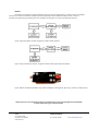
- Disabling the LED blinking F-S indication - This function can be disabled by soldering pair of pads (bottom side under the
RCVR wires marked as [A] at the end of this manual). From now there will be only active ON and OFF function (see figure
below).
SETLO
os. Przyjaźni 13/80
61-687 Poznań, POLAND
www.setlo.com
Technical support:
Tel.: +48 535 792 010
e-mail: [email protected]